Page 998 of 1954
Removal
NOTE: Usin g solven t an d a brush , was h an y oi l an d dir t
of f th e valv e bod y uni t it s lines , an d th e en d i f th e gear -
box . Blo w dr y wit h compresse d air .
1 . Drai n th e powe r steerin g flui d a s describe d o n pag e
17-16 .
2. Rais e th e fron t o f vehicle , an d suppor t i t o n safet y
stand s in th e prope r location s (se e sectio n 1 ).
3 . Remov e th e fron t wheels .
4 . Remov e th e driver' s airba g assembl y an d steerin g
whee l (se e pag e 17-18 ).
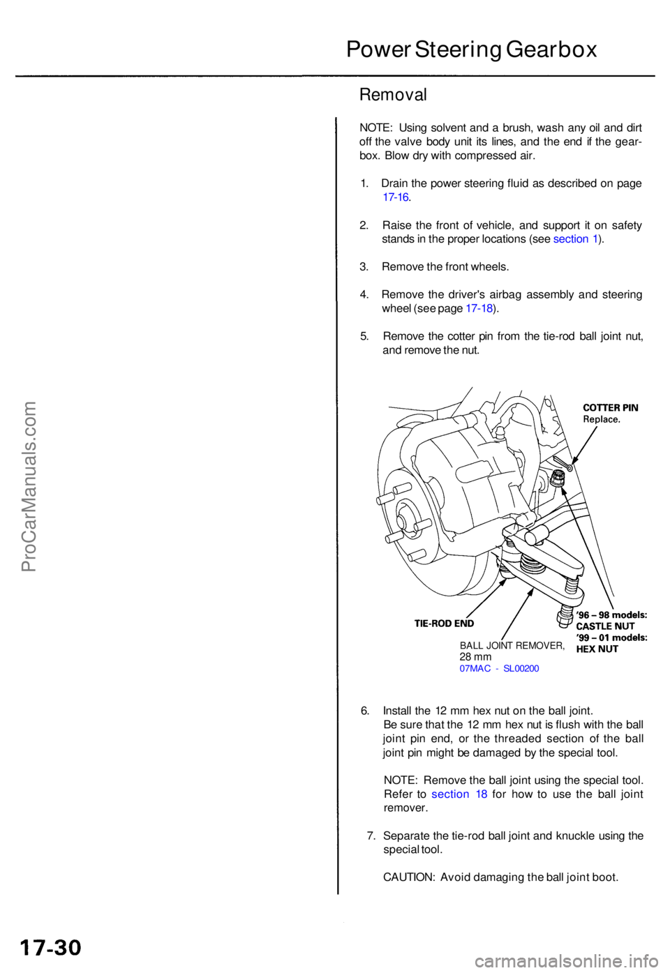
5 . Remov e th e cotte r pi n fro m th e tie-ro d bal l join t nut ,
an d remov e th e nut .
Powe r Steerin g Gearbo x
6. Instal l th e 1 2 m m he x nu t o n th e bal l joint .
B e sur e tha t th e 1 2 m m he x nu t i s flus h wit h th e bal l
join t pi n end , o r th e threade d sectio n o f th e bal l
join t pi n migh t b e damage d b y th e specia l tool .
NOTE : Remov e th e bal l join t usin g th e specia l tool .
Refe r t o sectio n 1 8 fo r ho w to us e th e bal l join t
remover .
7. Separat e th e tie-ro d bal l join t an d knuckl e usin g th e
specia l tool .
CAUTION : Avoi d damagin g th e bal l join t boot .
BALL JOIN T REMOVER ,28 m m07MA C - SL0020 0
ProCarManuals.com
Page 1002 of 1954
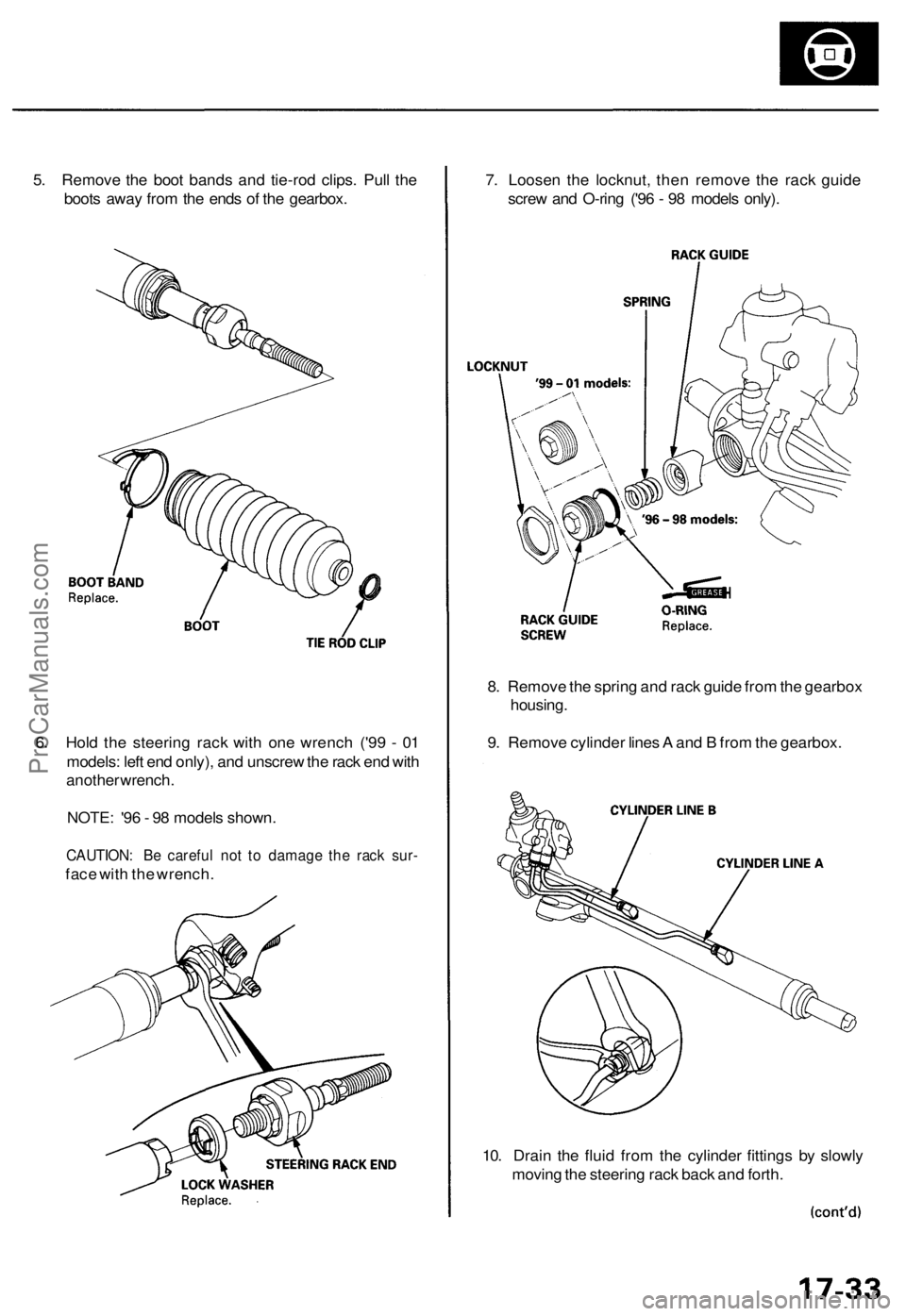
5. Remove the boot bands and tie-rod clips. Pull the
boots away from the ends of the gearbox.
6. Hold the steering rack with one wrench ('99 - 01
models: left end only), and unscrew the rack end with
another wrench.
NOTE: '96 - 98 models shown.
CAUTION: Be careful not to damage the rack sur-
face with the wrench.
7. Loosen the locknut, then remove the rack guide
screw and O-ring ('96 - 98 models only).
8. Remove the spring and rack guide from the gearbox
housing.
9. Remove cylinder lines A and B from the gearbox.
10. Drain the fluid from the cylinder fittings by slowly
moving the steering rack back and forth.ProCarManuals.com
Page 1018 of 1954
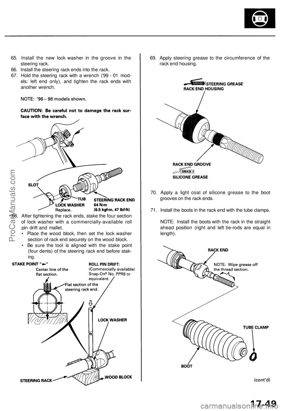
65. Install the new lock washer in the groove in the
steering rack.
66. Install the steering rack ends into the rack.
67. Hold the steering rack with a wrench ('99 - 01 mod-
els: left end only), and tighten the rack ends with
another wrench.
69. Apply steering grease to the circumference of the
rack end housing.
70. Apply a light coat of silicone grease to the boot
grooves on the rack ends.
71. Install the boots in the rack end with the tube clamps.
NOTE: Install the boots with the rack in the straight
ahead position (right and left tie-rods are equal in
length).
68. After tightening the rack ends, stake the four section
of lock washer with a commercially-available roll
pin drift and mallet.
• Place the wood block, then set the lock washer
section of rack end securely on the wood block.
• Be sure the tool is aligned with the stake point
(four dents) of the steering rack end before stak-
ing.ProCarManuals.com
Page 1019 of 1954
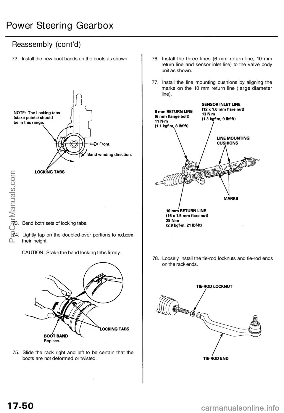
75. Slid e th e rac k righ t an d lef t t o b e certai n tha t th e
boot s ar e no t deforme d o r twisted . 78
. Loosel y instal l th e tie-ro d locknut s an d tie-ro d end s
o n th e rac k ends .
73
. Ben d bot h set s o f lockin g tabs .
74 . Lightl y ta p o n th e doubled-ove r portion s t o reduc e
thei r height .
CAUTION : Stak e th e ban d lockin g tab s firmly . 76
. Instal l th e thre e line s ( 6 m m retur n line , 1 0 m m
retur n lin e an d senso r inle t line ) t o th e valv e bod y
uni t a s shown .
77 . Instal l th e lin e mountin g cushion s b y alignin g th e
mark s o n th e 1 0 m m retur n lin e (larg e diamete r
line).
Reassembl y (cont'd )
72. Instal l th e ne w boo t band s o n th e boot s a s shown .
Power Steerin g Gearbo x
ProCarManuals.com
Page 1023 of 1954
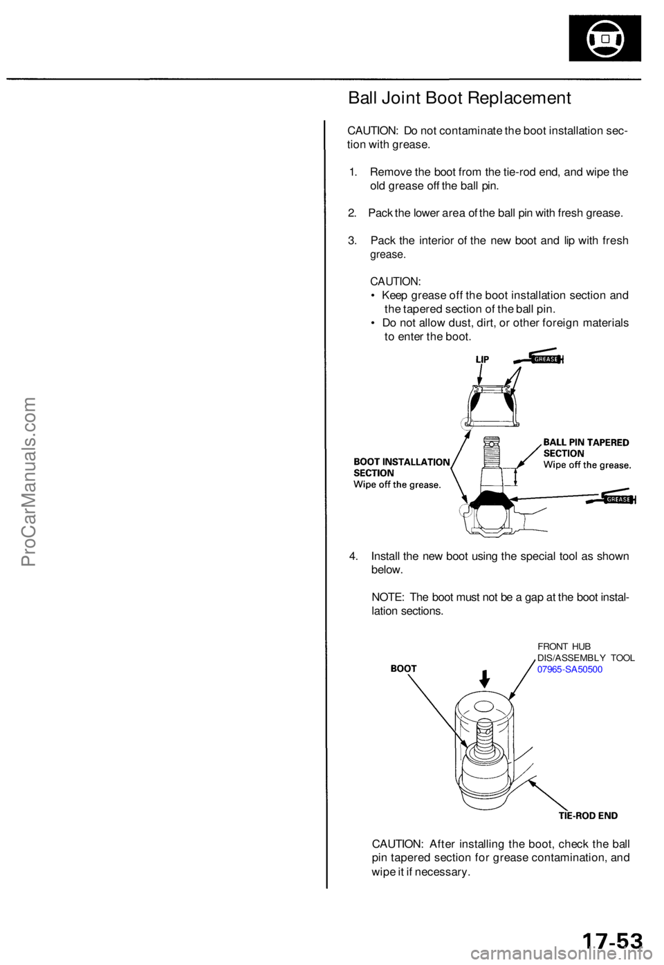
Ball Join t Boo t Replacemen t
CAUTION: D o no t contaminat e th e boo t installatio n sec -
tio n wit h grease .
1 . Remov e th e boo t fro m th e tie-ro d end , an d wip e th e
ol d greas e of f th e bal l pin .
2 . Pac k th e lowe r are a o f th e bal l pi n wit h fres h grease .
3 . Pac k th e interio r o f th e ne w boo t an d li p wit h fres h
grease .
CAUTION :
• Kee p greas e of f th e boo t installatio n sectio n an d
th e tapere d sectio n o f th e bal l pin .
• D o no t allo w dust , dirt , o r othe r foreig n material s
t o ente r th e boot .
4 . Instal l th e ne w boo t usin g th e specia l too l a s show n
below .
NOTE : Th e boo t mus t no t b e a ga p a t th e boo t instal -
latio n sections .
CAUTION : Afte r installin g th e boot , chec k th e bal l
pi n tapere d sectio n fo r greas e contamination , an d
wip e it i f necessary .
FRONT HU B
DIS/ASSEMBL Y TOO L
0796 5-SA5050 0
ProCarManuals.com
Page 1027 of 1954
Front Toe Inspection/Adjustment
NOTE: Use commercially-available computerized four
wheel alignment equipment to measure wheel align-
ment (caster, camber, toe, and/or turning angle).
Follow the equipment manufacturer's instructions.
1. Check the tire pressure.
2. Center the steering wheel spokes.
3. Check the toe with the wheels pointed straight
ahead.
Front toe: 0 ± 2 mm (0±1/16 in)
— If adjustment is required, go on to step 4.
— If no adjustment is required, remove the align-
ment equipment.
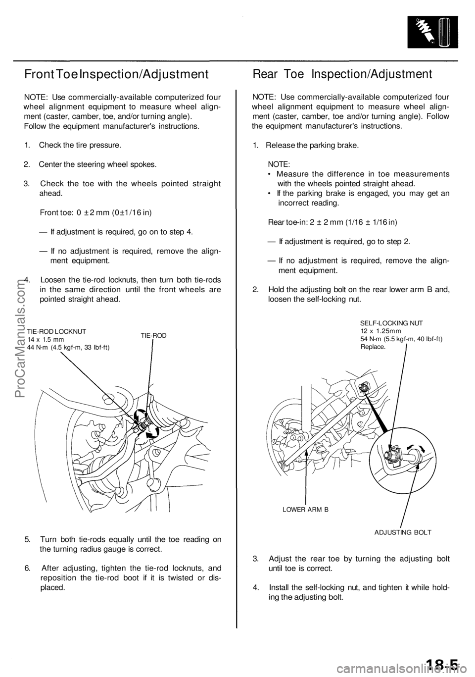
4. Loosen the tie-rod locknuts, then turn both tie-rods
in the same direction until the front wheels are
pointed straight ahead.
TIE-ROD LOCKNUT
14 x 1.5 mm
44 N-m (4.5 kgf-m, 33 Ibf-ft)
TIE-ROD
5. Turn both tie-rods equally until the toe reading on
the turning radius gauge is correct.
6. After adjusting, tighten the tie-rod locknuts, and
reposition the tie-rod boot if it is twisted or dis-
placed.
Rear Toe Inspection/Adjustment
NOTE: Use commercially-available computerized four
wheel alignment equipment to measure wheel align-
ment (caster, camber, toe and/or turning angle). Follow
the equipment manufacturer's instructions.
1. Release the parking brake.
NOTE:
• Measure the difference in toe measurements
with the wheels pointed straight ahead.
• If the parking brake is engaged, you may get an
incorrect reading.
Rear toe-in: 2 ± 2 mm (1/16 ± 1/16 in)
— If adjustment is required, go to step 2.
— If no adjustment is required, remove the align-
ment equipment.
2. Hold the adjusting bolt on the rear lower arm B and,
loosen the self-locking nut.
SELF-LOCKING NUT
12 x 1.25mm
54 N-m (5.5 kgf-m, 40 Ibf-ft)
Replace.
LOWER ARM B
ADJUSTING BOLT
3. Adjust the rear toe by turning the adjusting bolt
until toe is correct.
4. Install the self-locking nut, and tighten it while hold-
ing the adjusting bolt.ProCarManuals.com
Page 1032 of 1954
Front Suspensio n
Knuckle/Hu b Replacemen t (cont'd )
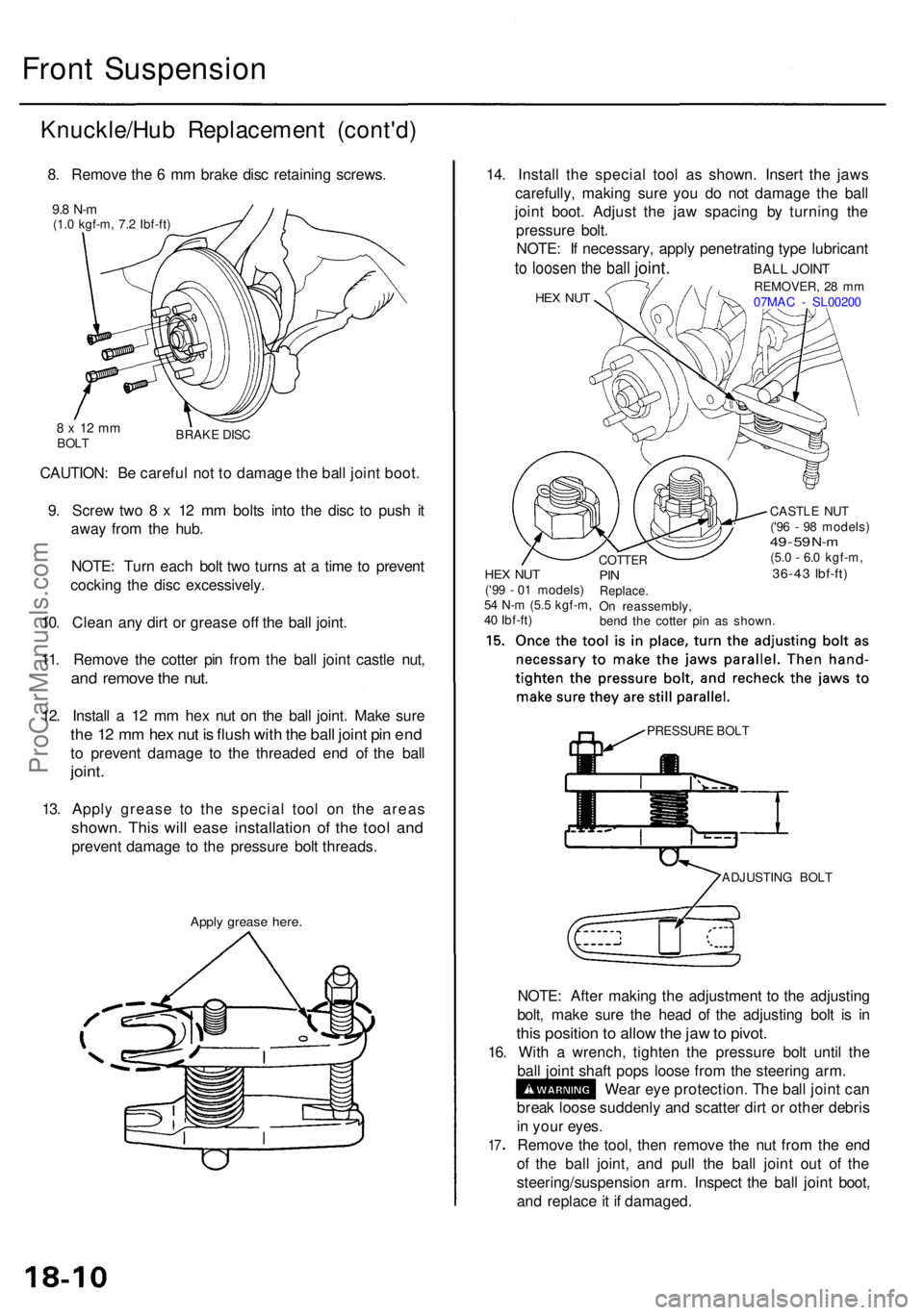
8. Remov e th e 6 m m brak e dis c retainin g screws .
9.8 N- m(1.0 kgf-m , 7. 2 Ibf-ft )
CAUTION : B e carefu l no t t o damag e th e bal l join t boot .
9 . Scre w tw o 8 x 1 2 m m bolt s int o th e dis c t o pus h i t
awa y fro m th e hub .
NOTE : Tur n eac h bol t tw o turn s a t a tim e t o preven t
cockin g th e dis c excessively .
10 . Clea n an y dir t o r greas e of f th e bal l joint .
11 . Remov e th e cotte r pi n fro m th e bal l join t castl e nut ,
and remov e th e nut .
12. Instal l a 12 m m he x nu t o n th e bal l joint . Mak e sur e
the 1 2 m m he x nu t i s flus h wit h th e bal l join t pi n en d
to preven t damag e t o th e threade d en d o f th e bal l
joint .
13. Appl y greas e t o th e specia l too l o n th e area s
shown . Thi s wil l eas e installatio n o f th e too l an d
preven t damag e t o th e pressur e bol t threads .
Apply greas e here .
ADJUSTIN G BOL T
NOTE : Afte r makin g th e adjustmen t t o th e adjustin g
bolt , mak e sur e th e hea d o f th e adjustin g bol t i s i n
thi s positio n to allo w th e ja w to pivot .
16. Wit h a wrench , tighte n th e pressur e bol t unti l th e
bal l join t shaf t pop s loos e fro m th e steerin g arm .
Wea r ey e protection . Th e bal l join t ca n
brea k loos e suddenl y an d scatte r dir t o r othe r debri s
i n you r eyes .
Remov e th e tool , the n remov e th e nu t fro m th e en d
o f th e bal l joint , an d pul l th e bal l join t ou t of the
steering/suspensio n arm . Inspec t th e bal l join t boot ,
an d replac e it i f damaged .
17
HE X NU TREMOVER , 2 8 m m
07MA C - SL0020 0
14. Instal l th e specia l too l a s shown . Inser t th e jaw s
carefully , makin g sur e yo u d o no t damag e th e bal l
join t boot . Adjus t th e ja w spacin g b y turnin g th e
pressur e bolt .
NOTE : I f necessary , appl y penetratin g typ e lubrican t
to loose n the bal l joint . BALL JOIN T
HEX NU T('99 - 0 1 models )
5 4 N- m (5. 5 kgf-m ,
4 0 Ibf-ft )
COTTE RPINReplace .On reassembly ,
ben d th e cotte r pi n a s shown .
CASTL
E NU T
('9 6 - 9 8 models )
49 - 5 9 N- m(5. 0 - 6. 0 kgf-m ,36-43 Ibf-ft )
PRESSUR E BOL T
8 x 1 2 m mBOL T BRAK
E DIS C
ProCarManuals.com
Page 1036 of 1954
Front Suspensio n
Ball Join t Boo t Replacemen t
1. Remov e th e se t rin g an d th e boo t
CAUTION : D o no t contaminat e th e boo t installatio n
sectio n wit h grease .
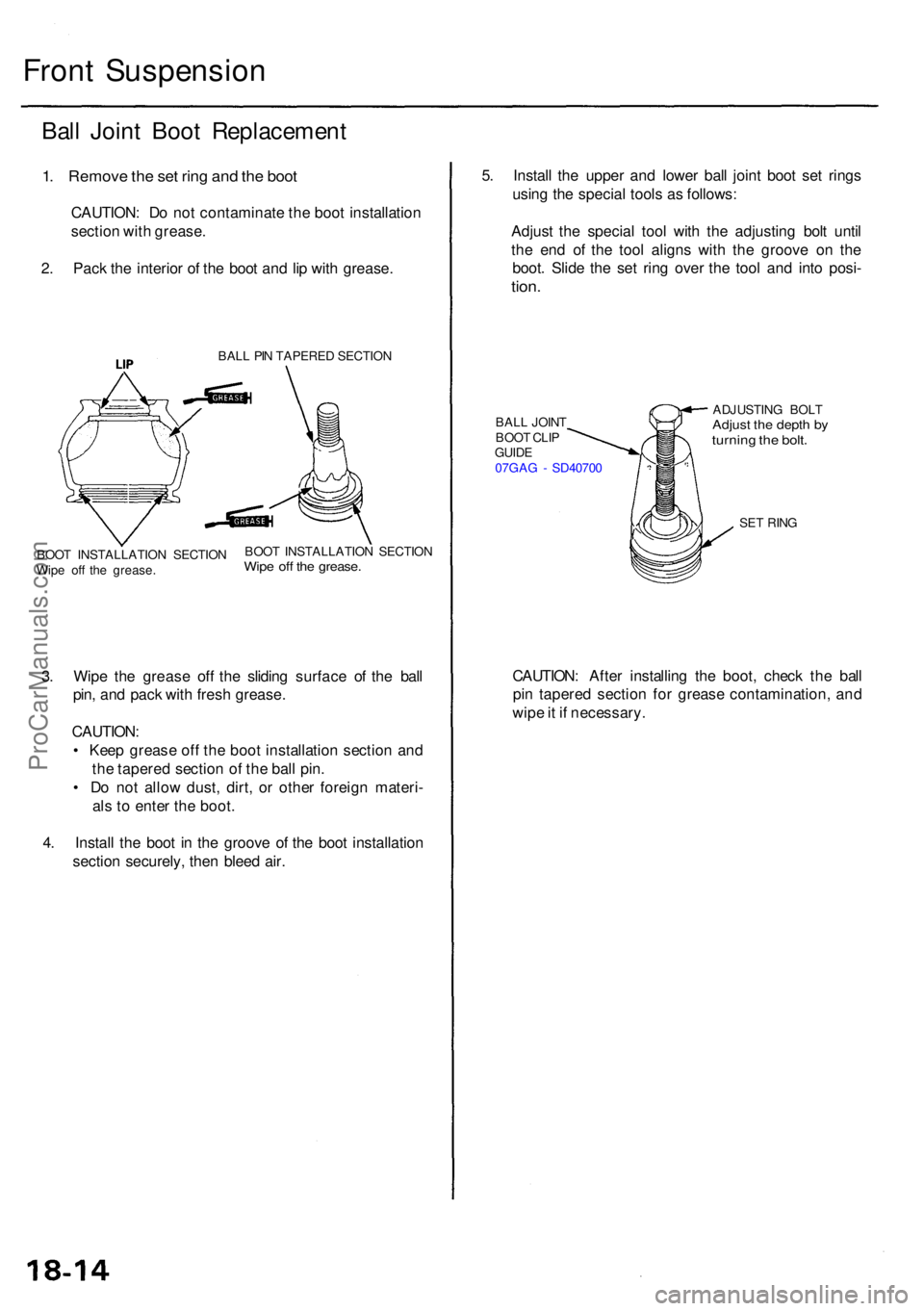
2 . Pac k th e interio r o f th e boo t an d li p wit h grease .
BALL PI N TAPERE D SECTIO N
3. Wip e th e greas e of f th e slidin g surfac e o f th e bal l
pin , an d pac k wit h fres h grease .
CAUTION :
• Kee p greas e of f th e boo t installatio n sectio n an d
th e tapere d sectio n o f th e bal l pin .
• D o no t allo w dust , dirt , o r othe r foreig n materi -
al s to ente r th e boot .
4 . Instal l th e boo t i n th e groov e o f th e boo t installatio n
sectio n securely , the n blee d air . 5
. Instal l th e uppe r an d lowe r bal l join t boo t se t ring s
usin g th e specia l tool s a s follows :
Adjus t th e specia l too l wit h th e adjustin g bol t unti l
th e en d o f th e too l align s wit h th e groov e o n th e
boot . Slid e th e se t rin g ove r th e too l an d int o posi -
tion.
BAL L JOIN T
BOO T CLI P
GUID E
07GA G - SD4070 0 ADJUSTIN
G BOL TAdjust th e dept h b yturnin g th e bolt .
SET RIN G
CAUTION : Afte r installin g th e boot , chec k th e bal l
pi n tapere d sectio n fo r greas e contamination , an d
wip e it i f necessary .
BOOT INSTALLATIO N SECTIO N
Wip e of f th e grease . BOO
T INSTALLATIO N SECTIO NWipe of f th e grease .
ProCarManuals.com