Page 468 of 1954

Replacement (cont'd )
3. Instal l th e oi l filte r b y hand .
4 . Afte r th e rubbe r sea l seats , tighte n th e oi l filte r
clockwis e wit h th e tool .
Tighten : 7/ 8 tur n clockwise .
Tightenin g torque : 2 2 N- m (2. 2 kgf-m , 1 6 Ibf-ft )
Oil Filte r
OIL FILTE R WRENC H07912-611000 1
Use thi s procedur e t o tighte n th e filte r i f eigh t number s
( 1 t o 8 ) ar e printe d o n th e surfac e o f th e filter .
1 ) Mak e a mar k o n th e oi l pa n unde r th e numbe r tha t
show s a t th e botto m o f th e filte r whe n th e rubbe r
sea l i s seated .
2 ) Tighte n th e filte r b y turnin g i t clockwis e seve n num -
ber s fro m th e marke d point . Fo r example , i f a mar k
i s mad e unde r th e numbe r 2 whe n th e rubbe r sea l
i s seated , th e filte r shoul d b e tightene d unti l th e
numbe r 1 come s u p to th e marke d point .
Numbe r whe n rubbe r Numbe r afte r tightening ,seal i s seated .
CAUTION : Usin g an y procedur e othe r tha n thos e
show n coul d resul t i n seriou s engin e damag e du e
t o oi l leakage .
5. Afte r installation , fil l th e engin e wit h oi l u p t o th e
specifie d level , ru n th e engine for mor e tha n thre e
minutes , the n chec k fo r oi l leakage .
ProCarManuals.com
Page 469 of 1954

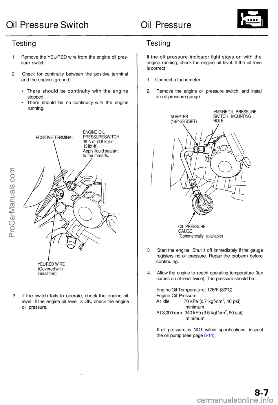
3. I f th e switc h fail s t o operate , chec k th e engin e oi l
level . I f th e engin e oi l leve l i s OK , chec k th e engin e
oi l pressure .
YEL/RED WIR E(Covere d wit hinsulation )
Testing
1. Remov e th e YEL/RE D wir e fro m th e engin e oi l pres -
sur e switch .
2 . Chec k fo r continuit y betwee n th e positiv e termina l
an d th e engin e (ground) .
• Ther e shoul d b e continuit y wit h th e engin e
stopped .
• Ther e shoul d b e n o continuit y wit h th e engin e
running .
POSITIV E TERMINA LENGIN
E OI L
PRESSUR E SWITC H
1 8 N- m (1. 8 kgf-m ,
1 3 Ibf-ft )
Apply liqui d sealan tto th e threads .
Oil Pressur e Switc hOil Pressur e
Testing
If th e oi l pressur e indicato r ligh t stay s o n wit h th e
engin e running , chec k th e engin e oi l level . I f th e oi l leve l
i s correct :
1 . Connec t a tachometer .
2 . Remov e th e engin e oi l pressur e switch , an d instal l
a n oi l pressur e gauge .
ADAPTE R(1/8"-28 BSPT ) ENGIN
E OI L PRESSUR E
SWITC H MOUNTIN GHOLE
OIL PRESSUR EGAUGE(Commerciall y available )
3. Star t th e engine . Shu t i t of f immediatel y i f th e gaug e
register s n o oi l pressure . Repai r th e proble m befor e
continuing .
4. Allo w th e engin e to reac h operatin g temperatur e (fa n
come s o n a t leas t twice) . Th e pressur e shoul d be :
Engin e Oi l Temperature : 176° F (80°C )
Engin e Oi l Pressure :
A t Idle : 7 0 kP a (0. 7 kgf/cm
2, 1 0 psi )
minimu m
At 3,00 0 rpm : 34 0 kP a (3. 5 kgf/cm2, 5 0 psi )
minimu m
I f oi l pressur e i s NO T withi n specifications , inspec t
th e oi l pum p (se e pag e 8-14 ).
ProCarManuals.com
Page 470 of 1954

Oil Pa n
Remova l
Engine remova l i s no t require d i n thi s procedure .
• Mak e sur e jack s an d safet y stand s ar e place d properl y
(se e sectio n 1 ).
• Appl y th e parkin g brak e an d bloc k th e rea r wheel s s o
th e vehicl e wil l no t rol l of f stand s whil e yo u ar e
workin g unde r it .
CAUTION :
• Us e fende r cover s t o avoi d damagin g painte d sur -
faces .
• Unplu g th e wirin g connector s carefull y whil e holdin g
th e connecto r portio n to avoi d damaging .
• Mar k al l wirin g an d hose s t o avoi d misconnection .
Also , b e sur e tha t the y d o no t contac t othe r wirin g
o r hose s o r interfer e wit h othe r parts .
1 . Loose n th e idle r pulle y cente r nu t an d adjustin g bolt ,
the n remov e th e ai r conditionin g (A/C ) compresso r
bel t (se e pag e 5-7 ).
2 . Disconnec t th e powe r steerin g pressur e (PSP )
switc h connector , the n remov e th e powe r steerin g
pum p bel t an d pum p (se e pag e 5-8 ).
3 . Remov e th e lef t an d righ t sid e exhaus t manifol d
covers (se e pag e 9-4 ).
4 . Rais e th e hois t t o ful l height .
5 . Remov e th e fron t tires/wheel s an d splas h shiel d
(se e pag e 5-8 ).
6 . Remov e th e dampe r fork s (se e sectio n 18 ).
7 . Disconnec t th e suspensio n lowe r ar m bal l joint s
with the specia l tool . Refe r t o sectio n 1 8 fo r th e
prope r procedure .
8 . Remov e th e driveshaft s an d intermediat e shaf t (se e
sectio n 16 ).
9 . Drai n th e differentia l oil . Reinstal l th e drai n plu g usin g
a ne w washe r (se e sectio n 15 ).
10 . Drai n th e engin e oil . Reinstal l th e drai n bol t usin g a
ne w washe r (se e pag e 8-4 ).
11 . Disconnec t th e vehicl e spee d senso r (VSS ) connec -
tor , the n remov e th e VSS/powe r steerin g spee d
senso r (se e pag e 5-9 ).
D o no t disconnec t th e flui d hoses .
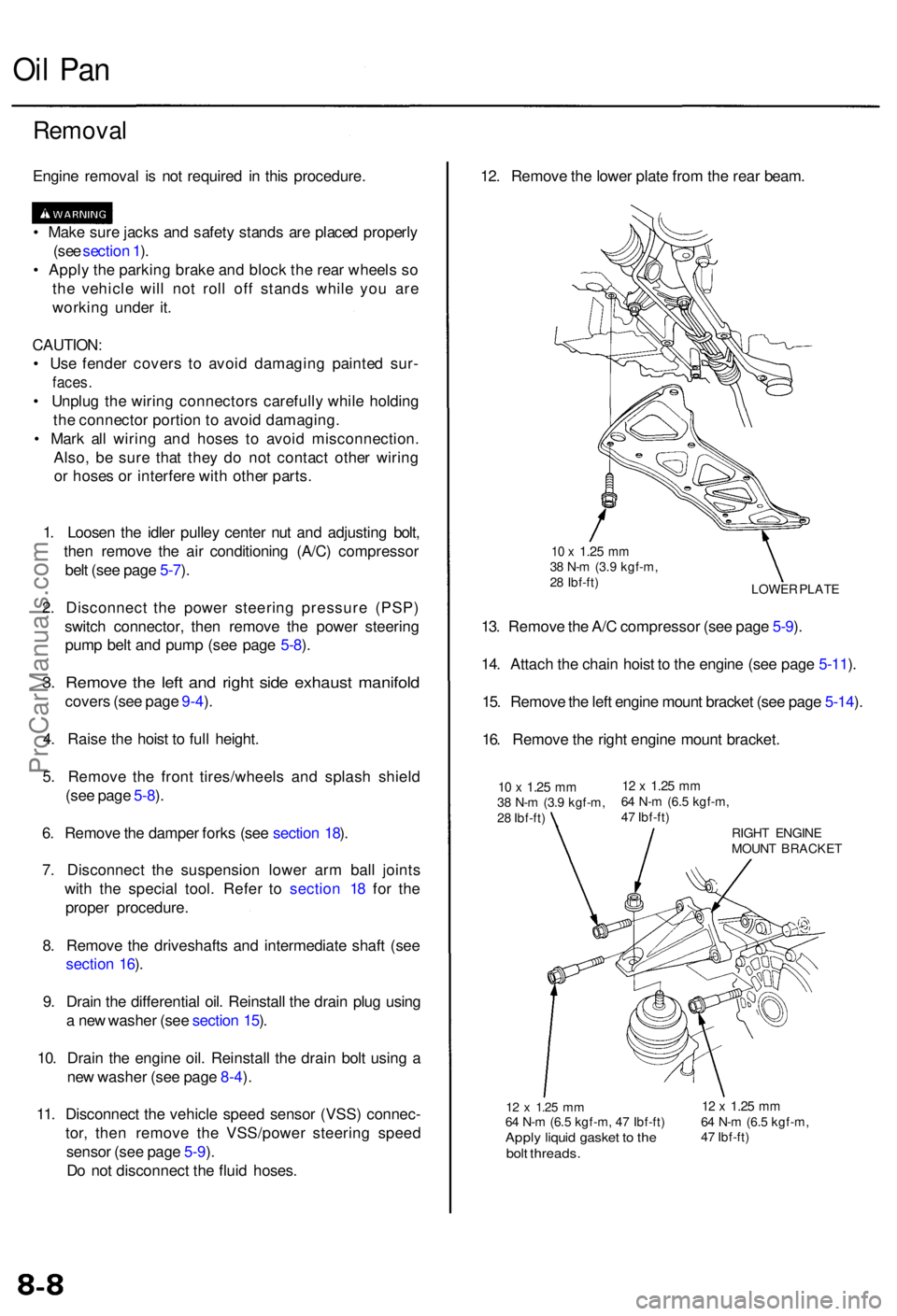
12 x 1.2 5 mm64 N- m (6. 5 kgf-m , 4 7 Ibf-ft )Apply liqui d gaske t t o th ebol t threads .
12 x 1.2 5 mm64 N- m (6. 5 kgf-m ,
4 7 Ibf-ft )
12. Remov e th e lowe r plat e fro m th e rea r beam .
LOWE R PLAT E
10 x 1.2 5 mm38 N- m (3. 9 kgf-m ,
2 8 Ibf-ft )
13. Remov e th e A/ C compresso r (se e pag e 5-9 ).
14 . Attac h th e chai n hois t t o th e engin e (se e pag e 5-11 ).
15 . Remov e th e lef t engin e moun t bracke t (se e pag e 5-14 ).
16 . Remov e th e righ t engin e moun t bracket .
10 x 1.2 5 mm38 N- m (3. 9 kgf-m ,
2 8 Ibf-ft )12 x 1.2 5 mm64 N- m (6. 5 kgf-m ,
4 7 Ibf-ft )
RIGHT ENGIN E
MOUN T BRACKE T
ProCarManuals.com
Page 472 of 1954

Oil Pan
Installation
Install the oil pan in the reverse order of removal:
• Always use new O-rings.
• Oil pan and cylinder block mating surface must be
clean.
1. Apply liquid gasket to the cylinder block, then install
the oil
pan.
NOTE:
• Use liquid gasket, Part No. 08718 - 0001 or 08718
0003.
• Check that the mating surfaces are clean and dry
before applying liquid gasket.
• Apply liquid gasket evenly, being careful to cover
all the mating surface.
• Do not apply liquid gasket to O-ring grooves.
• To prevent oil leakage, apply liquid gasket to the
inner threads of the bolt holes.
• Do not install the parts if 5 minutes or more have
elapsed since applying liquid gasket.
Instead, reapply liquid gasket after removing old
residue.
•
After assembly,
wait
at
least
30
minutes before
fill-
ing the engine with oil.
CYLINDER
BLOCK
O-RING GROOVE
Apply liquid gasket
along the broken line.
NOTE: Use new O-rings. Apply oil to the O-rings
before installation.
DOWEL PIN
O-RINGS
Replace.
DOWEL PIN
OIL PAN
ASSEMBLY
8 x
1.25
mm
22 N-m (2.2 kgf-m,
16 Ibf-ft)
2. Tighten the oil pan bolts as shown.
OIL PAN BOLT TORQUE SEQUENCE
8 x 1.25 mm: 22 N-m (2.2 kgf-m, 16 Ibf-ft)ProCarManuals.com
Page 473 of 1954

3. Instal l th e differentia l assembly .
Selec t th e appropriat e 2 6 m m shi m wheneve r th e
oi l pa n o r th e cylinde r bloc k i s replaced .
Refe r t o sectio n 1 5 fo r selectio n o f th e correc t
26 m m shim .
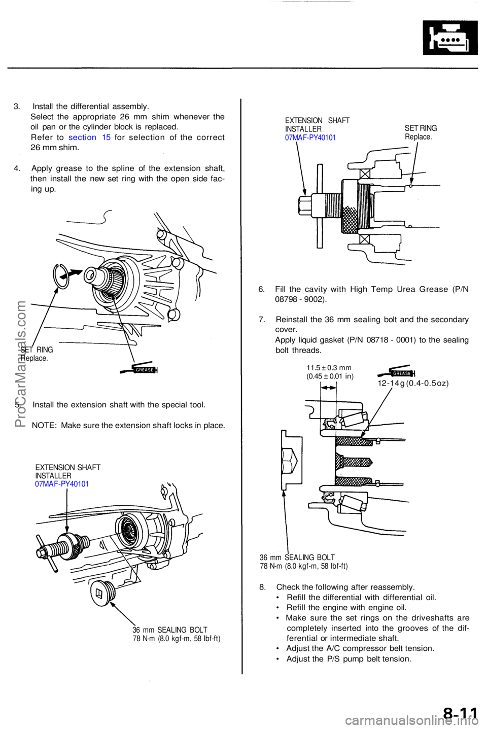
4. Appl y greas e t o th e splin e o f th e extensio n shaft ,
the n instal l th e ne w se t rin g wit h th e ope n sid e fac -
ing up .
EXTENSIO N SHAF T
INSTALLE R
07MA F-PY4010 1SET RIN GReplace .
6. Fil l th e cavit y wit h Hig h Tem p Ure a Greas e (P/ N
0879 8 - 9002) .
7 . Reinstal l th e 3 6 m m sealin g bol t an d th e secondar y
cover .
Appl y liqui d gaske t (P/ N 0871 8 - 0001 ) t o th e sealin g
bol t threads .
11.5 ± 0. 3 m m(0.4 5 ± 0.01 in)12 -1 4 g (0.4-0. 5 oz )
36 m m SEALIN G BOL T
7 8 N- m (8. 0 kgf-m , 5 8 Ibf-ft )
8. Chec k th e followin g afte r reassembly .
• Refil l th e differentia l wit h differentia l oil .
• Refil l th e engine with engin e oil .
• Mak e sur e th e se t ring s o n th e driveshaft s ar e
completel y inserte d int o th e groove s o f th e dif -
ferentia l o r intermediat e shaft .
• Adjus t th e A/ C compresso r bel t tension .
• Adjus t th e P/ S pum p bel t tension .
36 m m SEALIN G BOL T
7 8 N- m (8. 0 kgf-m , 5 8 Ibf-ft )
EXTENSIO N SHAF TINSTALLE R07MAF-PY4010 1
5. Instal l th e extensio n shaf t wit h th e specia l tool .
NOTE : Mak e sur e th e extensio n shaf t lock s in place .
SET RIN G
Replace .
ProCarManuals.com
Page 475 of 1954
Removal/lnspection/lnstallation
NOTE: To remove the oil pump, the engine must be
removed from the vehicle and separated from the trans-
mission.
1. Remove the balancer gear case.
O-RING
Replace.
BALANCER GEAR
CASE
DOWEL
PIN
2. Remove the balancer shaft rear cover.
BALANCER SHAFT
REAR COVER
O-RING
Replace.
BALANCER
SHAFT
3. Hold the balancer shaft as shown below, then remove
the rear balancer weight.
4. Pull out the balancer shaft.
NOTE: Take care not to damage the journals when
removing the balancer shaft.
REAR BALANCER
WEIGHTProCarManuals.com
Page 487 of 1954

Radiator
Illustrate d Inde x
Syste m is unde r hig h pressur e whe n th e
engin e i s hot . T o avoi d dange r o f releasin g scaldin g
coolant , remov e th e ca p onl y whe n th e engin e is cool .
Tota l Coolin g Syste m Capacit y (Includin g heate r an d
reservoir )
8.6 (9. 1 US qt , 7. 6 Im p qt )
Reservoi r capacity : 0.6 5 (0.6 9 U S qt , 0.5 7 Im p qt ) CAUTION
: Whe n pourin g engin e coolant , b e sur e t o
shu t th e rela y bo x li d an d no t t o spil l coolan t o n th e elec -
trica l part s o r th e painte d portion . I f an y coolan t spills ,
rins e it of f immediately .
NOTE:
Check al l coolin g syste m hose s fo r damage , leak s o r
deterioratio n an d replac e if necessary .
Chec k al l hos e clamp s an d retighte n i f necessary .
Us e ne w O-ring s whe n reassembling .
AUTOMATIC TRANSMISSIO NFLUID (ATF ) COOLE R HOSE SRefer t o sectio n 1 4 whe ninstalling .
RADIATO R CA PPressur e testing , pag e 10-7
6 x 1. 0 m m9 N- m (0. 9 kgf-m ,7 Ibf-ft )
RADIATO REngine coolan tRefilling an d bleeding , pag e 10-6Lea k test , pag e 10-7Inspec t soldere d joint s an dseam s fo r leaks .Blow ou t dir t fro m betwee ncore fin s wit h compresse d air .If insects , etc. , ar e cloggin gradiator, was h the m of f wit hlow-pressur e water .
CONDENSE RFAN SHROU D
6 x 1. 0 m m7 N- m (0. 7 kgf-m ,5 Ibf-ft )
O-RIN GReplace .
RADIATO R FA NCONTRO L SENSO R27 N- m (2. 8 kgf-m ,20 Ibf-ft )
FAN MOTO RRADIATO R FA NSHROU D
RADIATO RFAN
LOWE R RADIATO RHOSE
SELF-LOCKIN G NU T5.4 N- m (0.5 5 kgf-m , 3. 3 Ibf-ft )
O-RIN GReplace .
DRAINPLUG
UPPE R RADIATO RHOSE
ProCarManuals.com
Page 488 of 1954
Engine Hos e Connections :
HEATERHOSES
FAS T IDL E THERM O
VALV E
HEATE RVALVE
WATE R BYPAS S
HOSE S
IDL E AI R
CONTRO L
VALV E
THERMOSTA THOUSING
REAR WATE R
OUTLE T
AT F COOLE R
HOSE S
Refe r t o sectio n 1 4
whe n installing .
ATF COOLE RLINES
COOLAN TRESERVOI R
ProCarManuals.com