Page 1990 of 2543
INSPECTION PROCEDURE
Check VSV for fuel pressure control.
(1) Remove VSV.
(2) Disconnect VSV connector.
(1) Measure resistance between terminals.
(2) Measure resistance between each terminal
and the body.
(1) Resistance: 33 Ð 39 � at 20°C (68°F)
(2) Resistance: 1 M� or higher
Check operation of VSV when battery positive
voltage is applied and released to the VSV termi-
nals.
Battery positive voltage is applied:
Air from port E is flowing out through the air fil-
ter.
Battery positive voltage is not applied:
Air from port E is flowing out through port G.
Replace VSV for fuel pressure control. EG±482
± ENGINE2JZ±GE ENGINE TROUBLESHOOTING
Page 1991 of 2543
(See page EG±404)
Check voltage between terminal FPU of engine control module connector
and body ground.
(1) Connect SST (check harness ªAº).
(See page EG±404)
SST 09990±01000
(2) Turn ignition switch ON.
Measure voltage between terminal FPU of engine
control module connector and body ground.
Voltage: 9 Ð 14 V
Proceed to next circuit inspection shown on
matrix chart (See page EG±408).
Repair or replace harness or connector.
Check and replace engine control module.
Check for open and short in harness and connector between engine control
module and VSV, VSV and EFI main relay (See page
IN±30).
± ENGINE2JZ±GE ENGINE TROUBLESHOOTING7EG±483
Page 1992 of 2543
TE1 TE2 Terminal Circuit
CIRCUIT DESCRIPTION
Terminal TE1 is located in data link connectors 1 and 2. Terminal TE2 is located ONLY in data link connector
2.
The data link connector 1 is located in the engine compartment and the data link connector 2 is located in the
cabin. When these terminals are connected with the E1 terminal, diagnostic trouble codes in normal mode or
test mode can be read from the malfunction indicator lamp on the telltale light RH.
EG±484± ENGINE2JZ±GE ENGINE TROUBLESHOOTING
Page 1993 of 2543

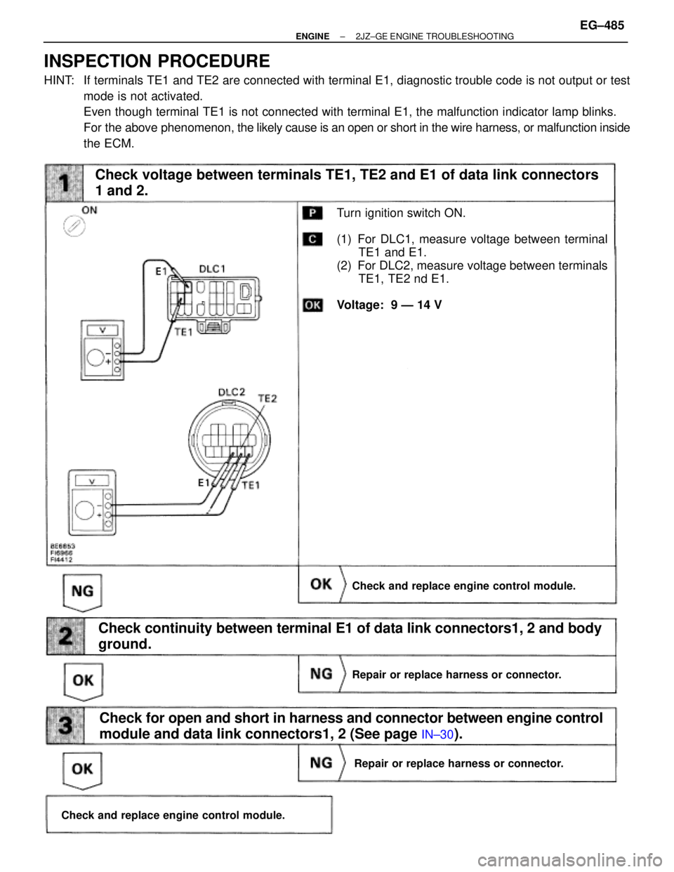
Check voltage between terminals TE1, TE2 and E1 of data link connectors
1 and 2.
Turn ignition switch ON.
(1) For DLC1, measure voltage between terminal
TE1 and E1.
(2) For DLC2, measure voltage between terminals
TE1, TE2 nd E1.
Voltage: 9 Ð 14 V
Check and replace engine control module.
Check continuity between terminal E1 of data link connectors1, 2 and body
ground.
Repair or replace harness or connector.
Check and replace engine control module.
Check for open and short in harness and connector between engine control
module and data link connectors1, 2 (See page
IN±30).
Repair or replace harness or connector.
INSPECTION PROCEDURE
HINT: If terminals TE1 and TE2 are connected with terminal E1, diagnostic trouble code is not output or test
mode is not activated.
Even though terminal TE1 is not connected with terminal E1, the malfunction indicator lamp blinks.
For the above phenomenon, the likely cause is an open or short in the wire harness, or malfunction inside
the ECM.
± ENGINE2JZ±GE ENGINE TROUBLESHOOTINGEG±485
Page 1994 of 2543
2JZ±GTE ENGINE TROUBLESHOOTING
EG±487
Page 1995 of 2543

P.
EG±489
P. EG±491, P.
EG±493
P.
EG±492
P. IN±24
P.
EG±492
P.
EG±506
P.
EG±494
P.
EG±514
P.
EG±515
P.
EG±505
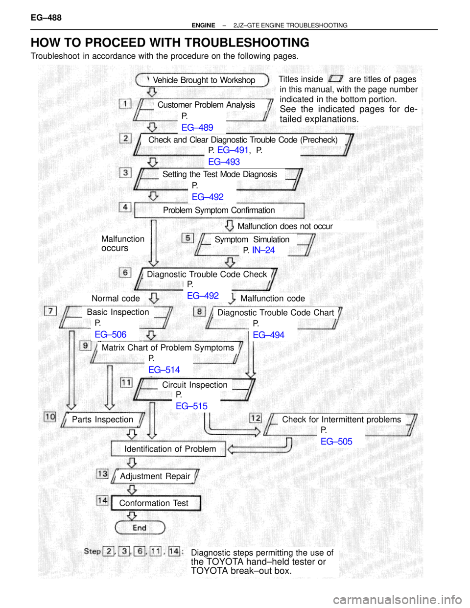
Vehicle Brought to Workshop
Customer Problem Analysis
Check and Clear Diagnostic Trouble Code (Precheck)
Setting the Test Mode Diagnosis
Problem Symptom Confirmation
Malfunction does not occur
Symptom Simulation
Diagnostic Trouble Code Check
Malfunction code
Diagnostic Trouble Code Chart
Malfunction
occurs
Normal code
Basic Inspection
Matrix Chart of Problem Symptoms
Circuit Inspection
Check for Intermittent problemsParts Inspection
Identification of Problem
Adjustment Repair
Conformation Test
Diagnostic steps permitting the use of
the TOYOTA hand±held tester or
TOYOTA break±out box.
Titles insideare titles of pages
in this manual, with the page number
indicated in the bottom portion.
See the indicated pages for de-
tailed explanations.
HOW TO PROCEED WITH TROUBLESHOOTING
Troubleshoot in accordance with the procedure on the following pages. EG±488
± ENGINE2JZ±GTE ENGINE TROUBLESHOOTING
Page 1996 of 2543
CUSTOMER PROBLEM ANALYSIS CHECK SHEET
± ENGINE2JZ±GTE ENGINE TROUBLESHOOTINGEG±489
Page 1997 of 2543

DIAGNOSIS SYSTEM
DESCRIPTION
The ECM contains a built±in self±diagnosis system by which
troubles with the engine signal network are detected and a Mal-
function Indicator Lamp on the instrument panel lights up.
By analyzing various signals as shown in a later table (See page
EG±494) the Engine Control Module (ECM) detects system mal-
functions relating to the sensors or actuators.
In the normal mode, the self±diagnosis system monitors 19 items,
indicated by code No. as shown in EG±494. A malfunction indica-
tor lamp informs the driver that a malfunction has been detected.
The lamp goes off automatically when the malfunction has been
repaired, but the diagnostic trouble code(s) remains stored in the
ECM memory (except for code Nos. 16 and 53). The ECM stores
the code(s) until it is cleared by removing the EFI No. 1 fuse with
the ignition switch OFF.
The diagnostic trouble code can be read by the number of blinks
of the malfunction indicator lamp when TE1 and E1 terminals on
the data link connector 1 or 2 are connected. When 2 or more
codes are indicated, the lowest number (code) will appear first.
In the test mode, 13 items, indicated by code No. as shown in
EG±494 are monitored. If a malfunction is detected in any one of
the systems indicated by code Nos. 13, 21, 22, 24, 25, 26, 27, 35,
41, 47, 71 and 78 the ECM lights the malfunction indicator lamp
to warn the technician that a malfunction has been detected. In
this case, TE2 and E1 terminals on the data link connector 2
should be connected as shown later. (See page EG±492).
In the test mode, even if the malfunction is corrected, the malfunc-
tion code is stored in the ECM memory even when the ignition
switch OFF (except code Nos. 43 and 51). The also applies in the
normal mode. The diagnostic trouble mode (normal or test) and
the output of the malfunction indicator lamp can be selected by
connecting the TE1, TE2 and E1 terminals on the data link con-
nector 2, as shown later.
A test mode function has been added to the functions of the self±
diagnosis system of the normal mode for the purpose of detecting
malfunctions such as poor contact, which are difficult to detect in
the normal mode. This function fills up the self±diagnosis system.
The test mode can be implemented by the technician following the
appropriate procedures of check terminal connection and opera-
tion described later. (See page EG±492) EG±490
± ENGINE2JZ±GTE ENGINE TROUBLESHOOTING