Page 1958 of 2543

DTC 52 53 55 Knock Sensor Circuit
Knock sensors are fitted one each to the front and rear of the left side of the cylinder block to detect
engine knocking. This sensor contains a piezoelectric element which generates a voltage when it be-
comes deformed, which occurs when the cylinder block vibrates due to knocking. If engine knocking
occurs, ignition timing is retarded to suppress it.
DTC No.Diagnostic Trouble Code Detecting ConditionTrouble Area
No No.1 knock sensor signal to ECM for 4
crank revolutions with engine speed between
1,600 rpm and 5,200 rpm
Engine control computer (for knock control)
malfunction at engine speed between 650 rpm
and 5,200 rpm
No No.2 knock sensor signal to ECM for 4 crank
revolutions with engine speed between 1,600
rpm and 5,200 rpm
�Open or short in No.1 knock sensor circuit
�No.1 knock sensor (looseness)
�ECM
�ECM
�Open or short in No.2 knock sensor circuit
�No.2 knock sensor (looseness)
�ECM
If the ECM detects the above diagnosis conditions, it operates the fail safe function in which the correc-
tive retard angle value is set to the maximum value.
DIAGNOSTIC TROUBLE CODE DETECTION DRIVING PATTERN
Purpose of the driving pattern.
(a) To simulate diagnostic trouble code detecting condition after diagnostic trouble code is recorded.
(b) To check that the malfunction is corrected when the repair is completed by confirming that diag±
nostic trouble code is no longer detected.
(1) Start the engine and warm up.
(2) Idle the engine for 3 min.
(3) With the A/C ON, race the engine quickly to 5,000 rpm 3 times.
(Rapidly depress the accelerator pedal and suddenly release it.)
HINT: If a malfunction exists, the malfunction indicator lamp will light up when sudden racing is
performed.
NOTICE: If the conditions in this test are not strictly followed, detection of the malfunction
will not be possible. EG±450
± ENGINE2JZ±GE ENGINE TROUBLESHOOTING
Page 1959 of 2543
INSPECTION PROCEDURE
HINT: If diagnostic trouble code 52 is displayed, check No.1 knock sensor (for front side) circuit.
If diagnostic trouble code 55 is displayed, check No.2 knock sensor (for rear side) circuit.
If diagnostic trouble code 53 is displayed, replace engine control module.
(See page
EG±404)
Check continuity between terminals KNK1, KNK2 of engine control module
connector and body ground.
(1) Connect SST (check harness ªAº).
(See page EG±404)
SST 09990±01000
(2) Disconnect the engine control modulecon±
nectors.
Measure resistance between terminals KNK1,
KNK2 of engine control module connector and
body ground.
Resistance: 1 M� or higher
± ENGINE2JZ±GE ENGINE TROUBLESHOOTINGEG±451
Page 1960 of 2543
 measure wave±
form between terminals KNK1, KNK2 of engine control
module and body ground.
HINT: The correct waveform is as shown.
�Sp")
INSPECTION USING OSCILLOSCOPE
�With the engine racing (4,000 rpm) measure wave±
form between terminals KNK1, KNK2 of engine control
module and body ground.
HINT: The correct waveform is as shown.
�Spread the time on the horizontal axis, and confirm that
the period of the wave is 123 � sec.
(Normal mode vibration frequency of knock sen±
sor: 8.1 KHz).
HINT: If normal mode vibration frequency is not 8.1 KHz,
the sensor is malfunctioning.
KNK Signal Waveform
5 msec./Division
100 � sec./Division
Check knock sensor.
Disconnect knock sensor connector.
Measure resistance between the knock sensor ter-
minal and body.
Resistance: 1 M� or higher
Replace knock sensor. (See page EG±245)
Repair or replace harness of connector.
Replace knock sensor. (See page EG±245)
Check and replace engine control module.
Check for open and short in harness and connector between engine control
module and knock sensor (See page
IN±30).
Does malfunction disappear when a good knock sensor is installed?
EG±452± ENGINE2JZ±GE ENGINE TROUBLESHOOTING
Page 1961 of 2543
.
CIRCUIT DESCRIPTION
The EGR system is designed to recirculate the exhaust gas, controlled according to the driving condi-
tions, back into the intake air±fuel mixture. It helps to")
(See page EG±397).
CIRCUIT DESCRIPTION
The EGR system is designed to recirculate the exhaust gas, controlled according to the driving condi-
tions, back into the intake air±fuel mixture. It helps to slow down combustion in the cylinder and thus
lower the combustion temperature which, in turn, reduces the amount of NOx emission. The amount
of EGR is regulated by the EGR vacuum modulator according to the load.
If even one of the following conditions is fulfilled,
the VSV is turned ON by a signal from the ECM.
This results in atmospheric air acting on the EGR
valve, closing the EGR valve and shutting off the
exhaust gas (EGR cut±OFF).
�Engine coolant temp. below 50°C (122°F)
�During deceleration (Throttle valve closed)
�Light engine load (amount of intake air very
small).
�Engine speed over 5,200 rpm
�Traction control is operating
DTC No.Diagnostic Trouble Code Detecting ConditionTrouble Area
EGR gas temp. is 70°C (158°F) or less for 1 ~
4 min. under conditions (a) and (b):
(2) trip detection logic)*
(a) Engine coolant temp.: 63°C (145°F) or
more
(b) EGR operation possible (Example A/T in
3rd speed (5th for M/T), A/C ON, 96
km/h (60 mph), Flat road)
�Open in EGR gas temp. sensor circuit
�Short in VSV circuit for EGR
�EGR hose disconnected, valve stuck
�Clogged EGR gas passage
�ECM
DIAGNOSTIC TROUBLE CODE DETECTION DRIVING PATTERN
Purpose of the driving pattern.
(a) To simulate diagnostic trouble code detecting condition after diagnostic trouble code is recorded.
(b) To check that the malfunction is corrected when the repair is completed by confirming that diag±
nostic trouble code is no longer detected.
DTC 71 EGR System Malfunction
± ENGINE2JZ±GE ENGINE TROUBLESHOOTINGEG±453
Page 1962 of 2543
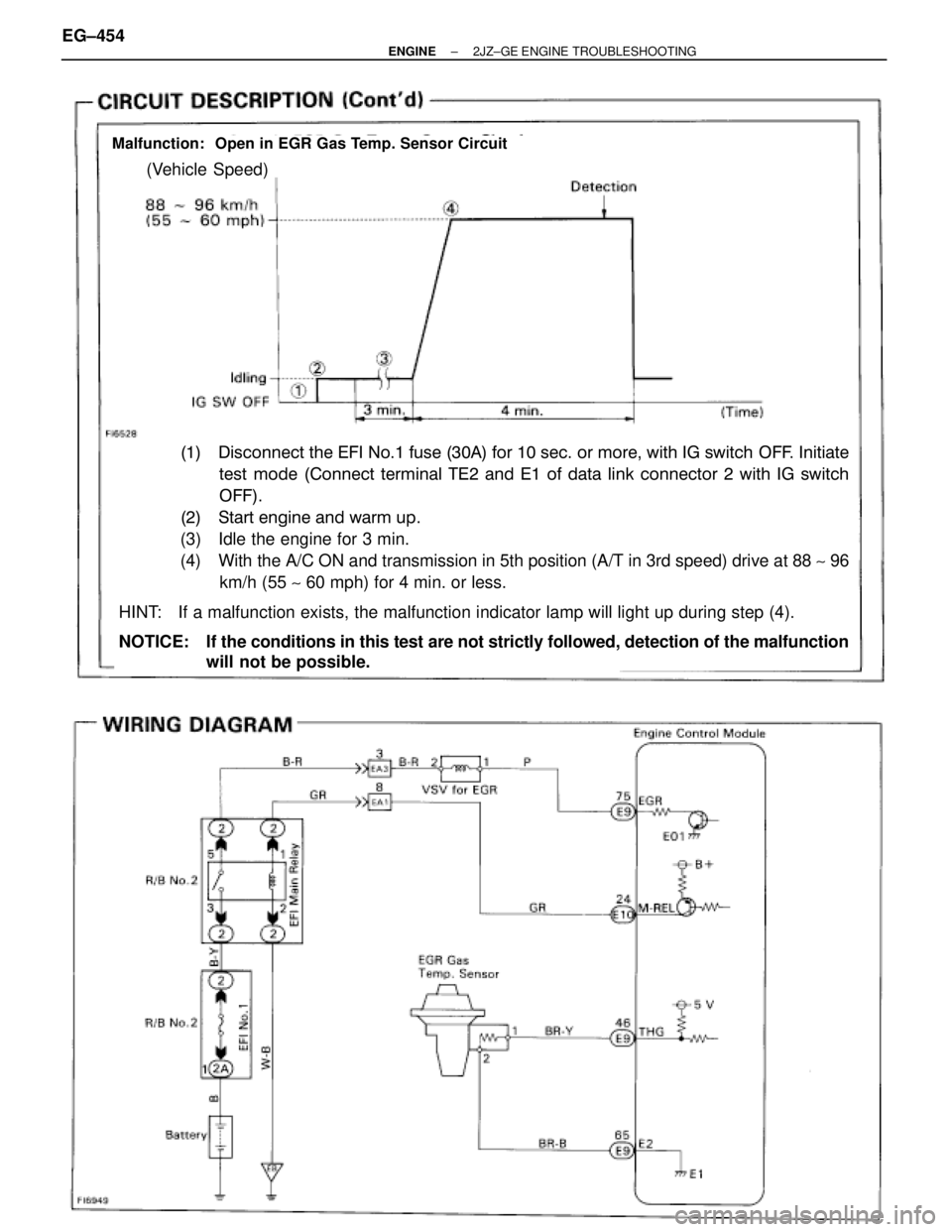
Malfunction: Open in EGR Gas Temp. Sensor Circuit
(Vehicle Speed)
(1)�Disconnect the EFI No.1 fuse (30A) for 10 sec. or more, with IG switch OFF. Initiate
���test mode (Connect terminal TE2 and E1 of data link connector 2 with IG switch
���OFF).
(2)�Start engine and warm up.
(3) Idle the engine for 3 min.
(4) With the A/C ON and transmission in 5th position (A/T in 3rd speed) drive at 88 ~ 96
km/h (55 ~ 60 mph) for 4 min. or less.
HINT: If a malfunction exists, the malfunction indicator lamp will light up during step (4).
NOTICE: If the conditions in this test are not strictly followed, detection of the malfunction
will not be possible. EG±454
± ENGINE2JZ±GE ENGINE TROUBLESHOOTING
Page 1963 of 2543
INSPECTION PROCEDURE
(See page
EG±404)
(See page
EG±240)
Check voltage between terminal EGR of engine control module connector
and body ground.
(1) Connect SST (check harness ªAº).
(See page EG±404)
SST 09990±0100
(2) Warm up engine to normal operating
temperature.
Measure voltage between terminal EGR of engine
control module connector and body ground.
Voltage: 9 Ð 14 V
Repair or replace harness of connector.
Check resistance between terminals of VSV for EGR.
Remove VSV for EGR. (See page EG±240)
Measure resistance between terminals of VSV for
EGR.
Resistance: 38.5 Ð 44.5 � at 20°C (68°F)
Check and replace engine control module.
Check for open and short in harness and connector between EFI main relay
and VSV for EGR, VSV for EGR and engine control module. (See page
IN±30)
Replace VSV for EGR.
± ENGINE2JZ±GE ENGINE TROUBLESHOOTINGEG±455
Page 1964 of 2543
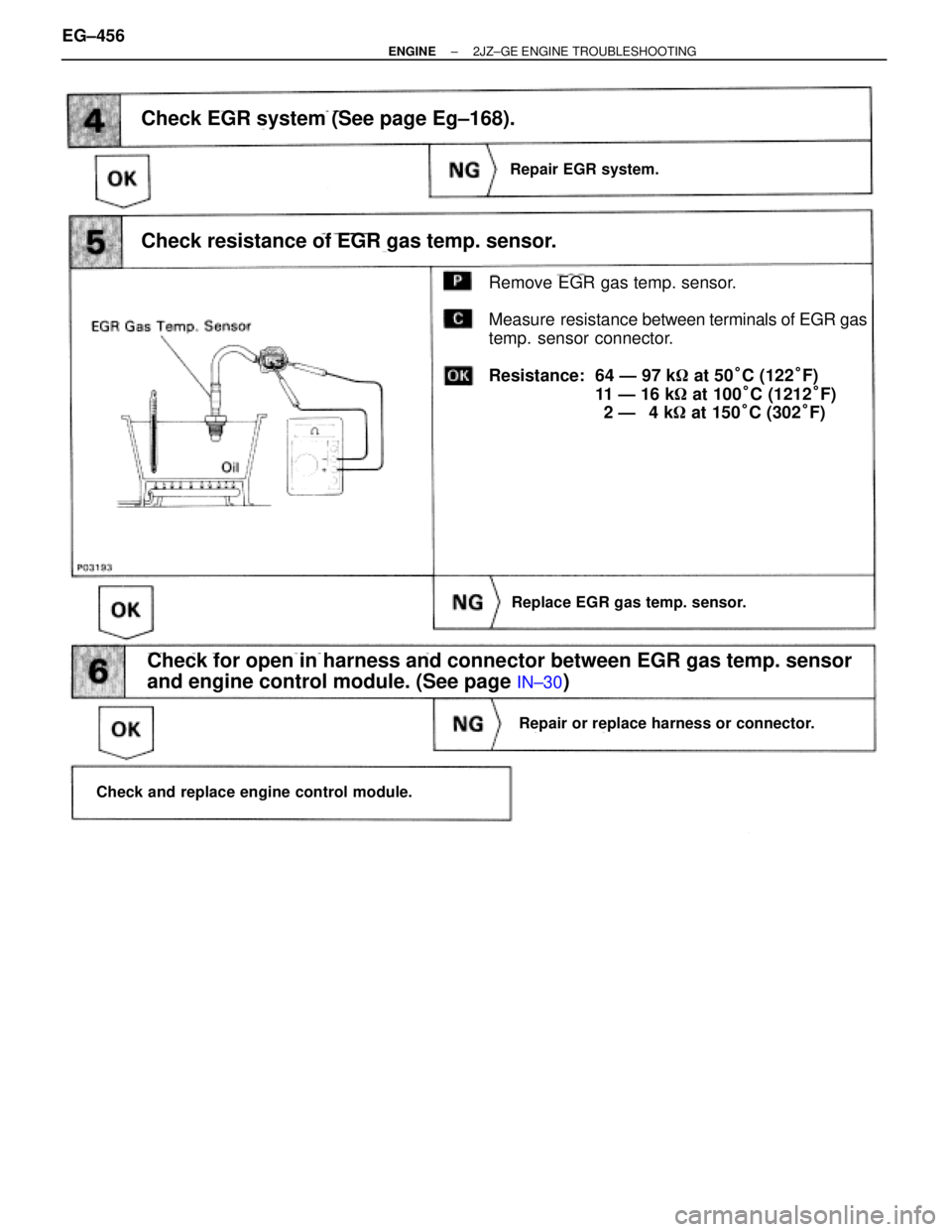
Check EGR system (See page Eg±168).
Remove EGR gas temp. sensor.
Measure resistance between terminals of EGR gas
temp. sensor connector.
Resistance: 64 Ð 97 k� at 50°C (122°F)
11 Ð 16 k� at 100°C (1212°F)
2 Ð 4 k� at 150°C (302°F)
Replace EGR gas temp. sensor.
Repair EGR system.
Replace EGR gas temp. sensor.
Repair or replace harness or connector.
Check and replace engine control module.
Check resistance of EGR gas temp. sensor.
Check for open in harness and connector between EGR gas temp. sensor
and engine control module. (See page
IN±30)
EG±456± ENGINE2JZ±GE ENGINE TROUBLESHOOTING
Page 1965 of 2543
 by the condition of the engine (starting,
light load, heavy load), when the en")
DTC 78 Fuel Pump Control Circuit
CIRCUIT DESCRIPTION
The fuel pump speed is controlled at 2 steps (high speed, low speed) by the condition of the engine (starting,
light load, heavy load), when the engine starts (STA ON), the engine control module sends a Hi signal (battery
positive voltage) to the fuel pump ECU (FPC terminal).
The fuel pump ECU then outputs Hi voltage (battery positive voltage) to the fuel pump so that the fuel pump
operates at high speed.
After the engine starts, during idling or light loads, the engine control module outputs a Low signal (about 9 V)
to the fuel pump ECU, the fuel pump ECU outputs Lo battery voltage (about 9 V) to the fuel pump and causes
the fuel pump to operate at low speed.
If the intake air volume increases (high engine load), the engine control module sends a Hi signal to the fuel
pump ECU and causes the fuel pump to operate at high speed.
����� �����DTC No.���������������� ����������������Diagnostic Trouble Code Detecting Condition��������������� ���������������Trouble Area����� �
���� �
���� �
���� �����
���������������� �
��������������� �
��������������� �
��������������� ����������������
(1) Open or short in fuel pump circuit for
1 sec. Or more with engine speed
1,000 rpm or less
(2 trip detection logic)*��������������� �
�������������� �
�������������� �
�������������� ���������������
O h i f l ECU i i����� �
���� �
���� �
���� �����
78
���������������� �
��������������� �
��������������� �
��������������� ����������������
2) Open in input circuit of fuel pump ECU
(FPC) with engine speed 1,000 rpm or
less
(2 trip detection logic)*��������������� �
�������������� �
�������������� �
�������������� ���������������
� Open or short in fuel pump ECU circuit
� Fuel pump ECU
� Engine control module power source circuit
� Fuel pump
�Engine control module
����� �
���� �
���� �����
���������������� �
��������������� �
��������������� ����������������
(3) Open or short in diagnostic signal line (DI)
of fuel pump ECU with engine speed
1,000 rpm or less
(2 trip detection logic)*��������������� �
�������������� �
�������������� ���������������
� Engine control module
*: See page EG±397.
± ENGINE2JZ±GE ENGINE TROUBLESHOOTINGEG±457
 circuit.
If diagnostic trouble code 55 is displayed, check No.2 knock sensor (for rear s")

(See page
EG±240)
Check voltage between terminal EGR of engine control module connector
and body ground.
(1) Connect SST (check harness ªAº).
(See page EG±")