Page 534 of 2543
MEASURE ACCUMULATOR BACK PRESSURE
NOTICE:
wDo the test at normal operating fluid temp. 50±805C (122±1765F).
wBe careful to prevent the oil pressure gauge hose from interfering with the exhaust pipe.
(a) Warm up the transmission fluid.
(b) Remove the test plug on the transmission case rear right side and connect the oil pressure gauge
(SST)
SST 09992±00094 (Oil pressure gauge)
HINT: Connecting the oil pressure gauge will be made easier by moving the RH side head insulator aside.
(c) Remove the passenger side floor carpet and ECM protector.
(d) Connect the SST (check harness A) between ECM and connector of vehicle wire harness.
SST: 09990±01000
(e) Install one test lead probe into the terminal SLN of the ECM wire harness side connector and take care
not to ground the other test lead probe.
HINT: Prepare test leads which are connected with an approximately 8 W light bulb. AT2±50
± A340E (2JZÐGTE) AUTOMATIC TRANSMISSIONTROUBLESHOOTING
Page 538 of 2543
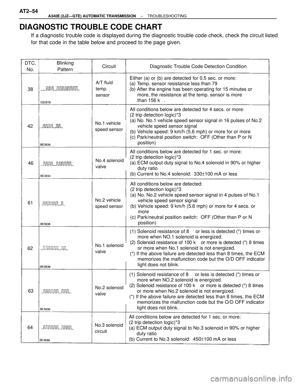
DTC.
No.Blinking
PatternCircuitDiagnostic Trouble Code Detection Condition
38
42
46
61
62
63
64
A/T fluid
temp.
sensor
No.1 vehicle
speed sensor
No.4 solenoid
valve
No.2 vehicle
speed sensor
No.1 solenoid
valve
No.2 solenoid
valve
No.3 solenoid
circuit
Either (a) or (b) are detected for 0.5 sec. or more:
(a) Temp. sensor resistance less than 79 �
(b) After the engine has been operating for 15 minutes or
more, the resistance at the temp. sensor is more
than 156 k��
All conditions below are detected for 4 secs. or more:
(2 trip detection logic)*3
(a) No. No.1 vehicle speed sensor signal in 16 pulses of No.2
vehicle speed sensor signal
(b) Vehicle speed: 9 km/h (5.6 mph) or more for or more
(c) Park/neutral position switch: OFF (Other than P or N
position)
All conditions below are detected for 1 sec. or more:
(2 trip detection logic)*3
(a) ECM output duty signal to No.4 solenoid in 90% or higher
duty ratio
(b) Current to No.4 solenoid: 330+100 mA or less
All conditions below are detected:
(2 trip detection logic)*3
(a) No. No.2 vehicle speed sensor signal in 4 pulses of No.1
vehicle speed sensor signal
(b) Vehicle speed: 9 km/h (5.6 mph) or more for 4 secs. or
more
(c) Park/neutral position switch: OFF (Other than P or N
position)
(1) Solenoid resistance of 8 ��or less is detected (*) times or
more when NO.1 solenoid is energized.
(2) Solenoid resistance of 100 k� or more is detected (*) 8 times
or more when No.1 solenoid is not energized.
(*) If the above failure are detected less than 8 times, the ECM
memorizes the malfunction code but the O/D OFF indicator
light does not blink.
(1) Solenoid resistance of 8 ��or less is detected (*) times or
more when NO.2 solenoid is energized.
(2) Solenoid resistance of 100 k� or more is detected (*) 8 times
or more when No.2 solenoid is not energized.
(*) If the above failure are detected less than 8 times, the ECM
memorizes the malfunction code but the O/D OFF indicator
light does not blink.
All conditions below are detected for 1 sec. or more:
(2 trip detection logic)*3
(a) ECM output duty signal to No.3 solenoid in 90% or higher
duty ratio
(b) Current to No.3 solenoid: 450+100 mA or less
DIAGNOSTIC TROUBLE CODE CHART
If a diagnostic trouble code is displayed during the diagnostic trouble code check, check the circuit listed
for that code in the table below and proceed to the page given. AT2±54
± A340E (2JZÐGTE) AUTOMATIC TRANSMISSIONTROUBLESHOOTING
Page 539 of 2543
�������������������� �
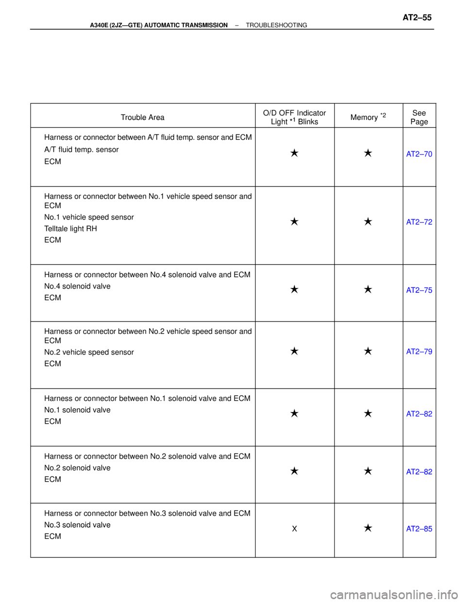
������������������� ��������������������Trouble Area
�������� �
������� ��������O/D OFF Indicator
Light *1Blinks
������� �
������ �������Memory *2
���� �
��� ����See
Page��������������������
Trouble Area
��������Light *1 Blinks�������
Memory
����Page�������������������� �
������������������� �
������������������� �
������������������� �
������������������� ��������������������
�Harness or connector between A/T fluid temp. sensor and ECM
�A/T fluid temp. sensor
�ECM
�������� �
������� �
������� �
������� �
������� ��������
�
������� �
������ �
������ �
������ �
������ �������
�
���� �
��� �
��� �
��� �
��� ����
AT2±70
�������������������� �
������������������� �
������������������� �
������������������� �
������������������� �
������������������� �
������������������� ��������������������
�Harness or connector between No.1 vehicle speed sensor and
ECM
�No.1 vehicle speed sensor
�Telltale light RH
�ECM
�������� �
������� �
������� �
������� �
������� �
������� �
������� ��������
�
������� �
������ �
������ �
������ �
������ �
������ �
������ �������
�
���� �
��� �
��� �
��� �
��� �
��� �
��� ����
AT2±72
�������������������� �
������������������� �
������������������� ��������������������
�Harness or connector between No.4 solenoid valve and ECM
�No.4 solenoid valve
�������� �
������� �
������� ���������
������� �
������ �
������ ��������
���� �
��� �
��� ����AT2±75
�������������������� �
������������������� ��������������������
�ECM�������� �
������� ��������
�
������� �
������ �������
�
���� �
��� ����
AT 2±75
�������������������� �
������������������� �
������������������� �
������������������� �
������������������� �
������������������� ��������������������
�Harness or connector between No.2 vehicle speed sensor and
ECM
�No.2 vehicle speed sensor
�ECM�������� �
������� �
������� �
������� �
������� �
������� ��������
�
������� �
������ �
������ �
������ �
������ �
������ �������
�
���� �
��� �
��� �
��� �
��� �
��� ����
AT2±79
�������������������� �
������������������� �
������������������� �
������������������� �
������������������� ��������������������
�Harness or connector between No.1 solenoid valve and ECM
�No.1 solenoid valve
�ECM�������� �
������� �
������� �
������� �
������� ��������
�
������� �
������ �
������ �
������ �
������ �������
�
���� �
��� �
��� �
��� �
��� ����
AT2±82
�������������������� �
������������������� ��������������������
�Harness or connector between No.2 solenoid valve and ECM
�No.2 solenoid valve�������� �
������� ���������
������� �
������ ��������
���� �
��� ����AT2±82�������������������� �
������������������� �
�������������������
�ECM�������� �
������� �
�������
�������� �
������ �
������
����� �
��� �
���
AT 2±82
�������������������� �
������������������� �
������������������� ��������������������
�Harness or connector between No.3 solenoid valve and ECM
�No.3 solenoid valve
�������� �
������� �
������� ��������X
������� �
������ �
������ ��������
���� �
��� �
��� ����AT 2 8 5�������������������� ��������������������
�No.3 solenoid valve
�ECM�������� ��������X������� ������������ ����AT2±85
�������������������� ���������������������������� ��������������� ����������� ����
± A340E (2JZÐGTE) AUTOMATIC TRANSMISSIONTROUBLESHOOTINGAT2±55
Page 548 of 2543
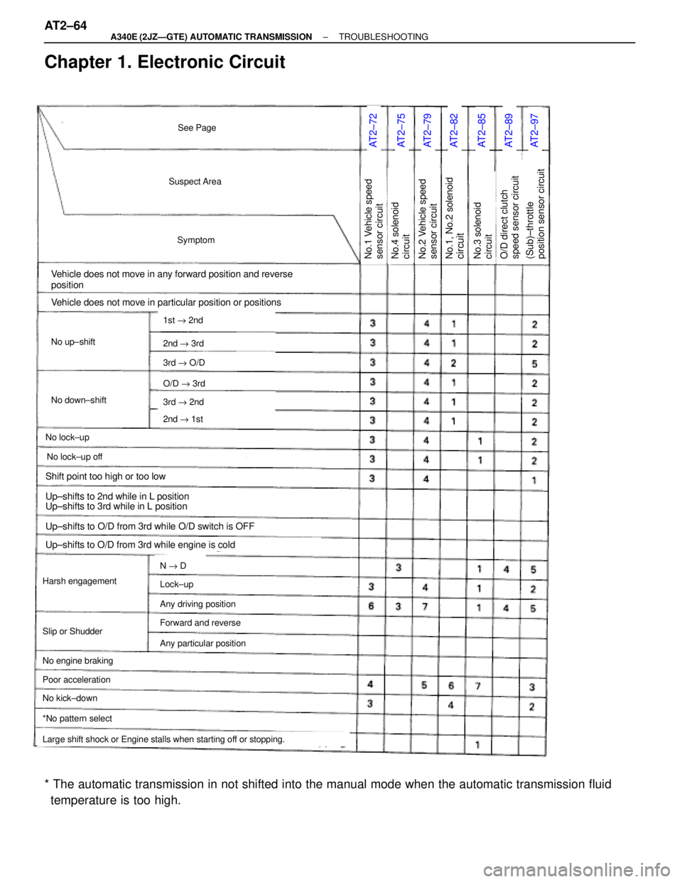
Chapter 1. Electronic Circuit
AT2±72AT2±75AT2±79AT2±82AT2±85AT2±89AT2±97
Suspect Area
Symptom
Vehicle does not move in any forward position and reverse
position
No up±shift
No down±shift
No lock±up
Vehicle does not move in particular position or positions
Harsh engagement
No engine braking
1st " 2nd
2nd " 3rd
3rd " O/D
O/D " 3rd
3rd " 2nd
2nd " 1st
N " D
Large shift shock or Engine stalls when starting off or stopping.
*No pattern select
No.1 Vehicle speed
sensor circuit
See Page
No lock±up off
Slip or Shudder
Poor acceleration
No kick±down
Lock±up
Any driving position
Forward and reverse
Any particular position
Shift point too high or too low
Up±shifts to 2nd while in L position
Up±shifts to 3rd while in L position
Up±shifts to O/D from 3rd while O/D switch is OFF
Up±shifts to O/D from 3rd while engine is cold
No.1, No.2 solenoidcircuitNo.2 Vehicle speed
sensor circuitNo.4 solenoid
circuitNo.3 solenoid
circuit(Sub)±throttle
position sensor circuitO/D direct clutch
speed sensor circuit
* The automatic transmission in not shifted into the manual mode when the automatic transmission fluid
temperature is too high. AT2±64
± A340E (2JZÐGTE) AUTOMATIC TRANSMISSIONTROUBLESHOOTING
Page 549 of 2543
AT2±101AT2±99AT2±103AT2±105AT2±108AT2±111EG±312AT2±60AT2±66AT2±68AT2±92BR±128AT2±70
Park/neutral position
switchPattern select switch
circuitStop light switch
circuitKick±down switch
circuitO/D switch O/D OFF
indicator light circuitEngine coolant temp.
sensor circuitO/D cancel signal
circuitECMNo.5 solenoid
circuitOFF±Vehicle repair
matrix chartOn±Vehicle repair
matrix chartTRAC ECUA/T fluid temp.
sensor circuit
± A340E (2JZÐGTE) AUTOMATIC TRANSMISSIONTROUBLESHOOTINGAT2±65
Page 554 of 2543
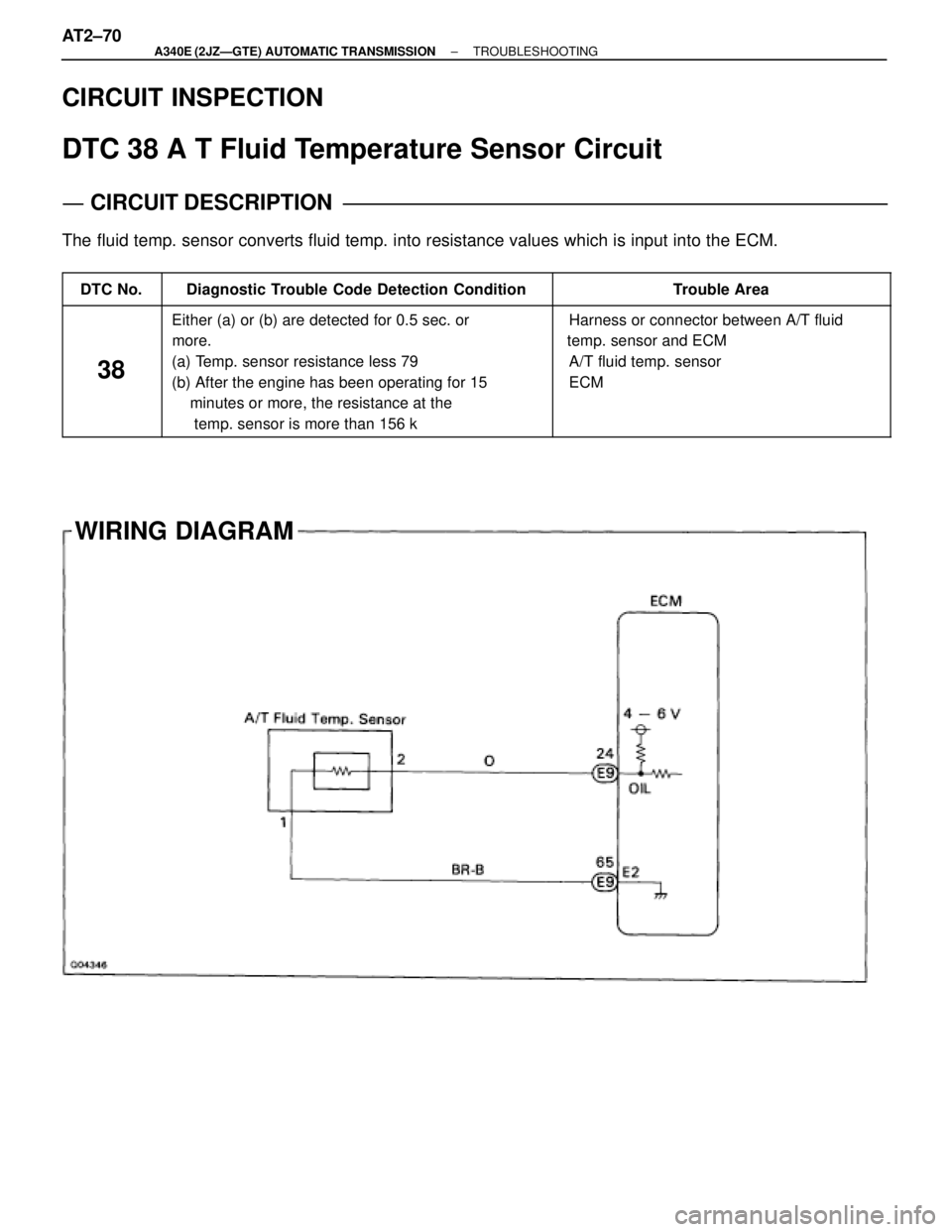
WIRING DIAGRAM CIRCUIT INSPECTION
DTC 38 A T Fluid Temperature Sensor Circuit
CIRCUIT DESCRIPTION
The fluid temp. sensor converts fluid temp. into resistance values which is input into the ECM.
����� �����DTC No.������������������ ������������������Diagnostic Trouble Code Detection Condition��������������� ���������������Trouble Area
����� �
���� �
���� �
���� �
���� �
���� �����
38
������������������ �
����������������� �
����������������� �
����������������� �
����������������� �
����������������� ������������������
Either (a) or (b) are detected for 0.5 sec. or
more.
(a) Temp. sensor resistance less 79 �
(b) After the engine has been operating for 15
minutes or more, the resistance at the
temp. sensor is more than 156 k ���������������� �
�������������� �
�������������� �
�������������� �
�������������� �
�������������� ���������������
� Harness or connector between A/T fluid
temp. sensor and ECM
� A/T fluid temp. sensor
� ECM
AT2±70± A340E (2JZÐGTE) AUTOMATIC TRANSMISSIONTROUBLESHOOTING
Page 555 of 2543
INSPECTION PROCEDURE
Check A/T fluid temp. sensor.
Check harness and connector between A/T fluid temp. sensor and ECM
(See page IN±30).
Replace A/T fluid temp. sensor.
Repair or replace harness or connector.
Check sensor resistance
Remove A/T fluid temp. sensor.
Measure resistance between terminals of A/T fluid
temp. sensor at 20°C (68°F) and 110°C (230°F).
Resistance:
20°C (68°F): Approx. 12.08 k�
11 0°C (230°F): Approx. 0.78 k�
20°C (68°F) and 110°C (230°F).
Check and replace ECM.
± A340E (2JZÐGTE) AUTOMATIC TRANSMISSIONTROUBLESHOOTINGAT2±71
Page 590 of 2543
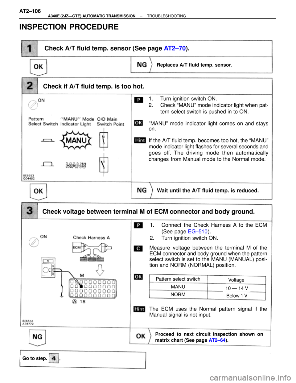
Check if A/T fluid temp. is too hot.
1. Turn ignition switch ON.
2. Check ªMANUº mode indicator light when pat-
tern select switch is pushed in to ON.
ºMANUº mode indicator light comes on and stays
on.
If the A/T fluid temp. becomes too hot, the ªMANUº
mode indicator light flashes for several seconds and
goes off. The driving mode then automatically
changes from Manual mode to the Normal mode.
Measure voltage between the terminal M of the
ECM connector and body ground when the pattern
select switch is set to the MANU (MANUAL) posi-
tion and NORM (NORMAL) position.
Check A/T fluid temp. sensor (See page AT2±70).
Check voltage between terminal M of ECM connector and body ground.
Replaces A/T fluid temp. sensor.
1. Connect the Check Harness A to the ECM
(See page EG±510).
2. Turn ignition switch ON.
Proceed to next circuit inspection shown on
matrix chart (See page AT2±64).
The ECM uses the Normal pattern signal if the
Manual signal is not input.
Pattern select switchVoltage
MANU
NORM
10 Ð 14 V
Below 1 V
Go to step.
Wait until the A/T fluid temp. is reduced.
INSPECTION PROCEDURE
AT2±106± A340E (2JZÐGTE) AUTOMATIC TRANSMISSIONTROUBLESHOOTING