Page 1185 of 2543
IF VEHICLE IS EQUIPPED WITH MOBILE
COMMUNICATION SYSTEM
For vehicles with mobile communication systems such as
two±way radios and cellular telephones, observe the follow-
ing precautions.
(1) Install the antenna as far as possible away from the ECM,
ECU and sensors of the vehicle's electronic system.
(2) Install the antenna feeder at least 20 cm (7.87 in.) away from
the ECM, ECU and sensors of the vehicle's electronics
systems. For details about ECM, ECU and sensors locations,
refer to the section on the applicable component.
(3) Do not wind the antenna feeder together with the other
wiring. As much as possible, also avoid running the antenna
feeder parallel with other wire harnesses.
(4) Confirm that the antenna and feeder are correctly adjusted.
(5) Do not install powerful mobile communications system. IN±18
± INTRODUCTIONPRECAUTION
Page 1204 of 2543

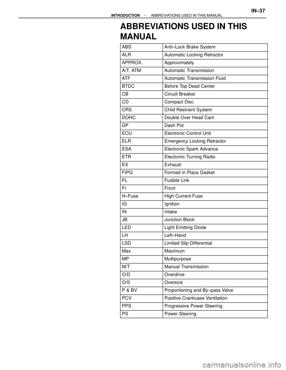
ABBREVIATIONS USED IN THIS
MANUAL
������� �������ABS���������������� ����������������Anti±Lock Brake System
������� �������ALR���������������� ����������������Automatic Locking Retractor
������� �������APPROX.���������������� ����������������Approximately
������� �������A/T, ATM���������������� ����������������Automatic Transmission
������� �������AT F���������������� ����������������Automatic Transmission Fluid
������� �������BTDC���������������� ����������������Before Top Dead Center
������� �������CB���������������� ����������������Circuit Breaker
������� �������CD���������������� ����������������Compact Disc������� �������CRS���������������� ����������������Child Restraint System������� �������DOHC���������������� ����������������Double Over Head Cam������� �
������ �������DP
���������������� �
��������������� ����������������Dash Pot
������� �������ECU���������������� ����������������Electronic Control Unit
������� �������ELR���������������� ����������������Emergency Locking Retractor
������� �������ESA���������������� ����������������Electronic Spark Advance
������� �������ETR���������������� ����������������Electronic Turning Radio
������� �������EX���������������� ����������������Exhaust
������� �������FIPG���������������� ����������������Formed in Place Gasket
������� �������FL���������������� ����������������Fusible Link
������� �������Fr���������������� ����������������Front������� �������H±Fuse���������������� ����������������High Current Fuse������� �
������ �������IG���������������� �
��������������� ����������������Ignition
������� �������IN���������������� ����������������Intake
������� �������JB���������������� ����������������Junction Block
������� �������LED���������������� ����������������Light Emitting Diode
������� �������LH���������������� ����������������Left±Hand
������� �������LSD���������������� ����������������Limited Slip Differential
������� �������Max.���������������� ����������������Maximum
������� �������MP���������������� ����������������Multipurpose
������� �������M/T���������������� ����������������Manual Transmission������� �������O/D���������������� ����������������Overdrive������� �������O/S���������������� ����������������Oversize������� �
������ �������P & BV
���������������� �
��������������� ����������������Proportioning and By±pass Valve
������� �������PCV���������������� ����������������Positive Crankcase Ventilation
������� �������PPS���������������� ����������������Progressive Power Steering
������� �������PS���������������� ����������������Power Steering
± INTRODUCTIONABBREVIATIONS USED IN THIS MANUALIN±37
Page 1480 of 2543

IF VEHICLE IS EQUIPPED WITH MOBIL
RADIO SYSTEM (HAM, CB, ETC.)
If the vehicle is equipped with a mobile communication sys-
tem, refer to the precaution in the IN section.
AIR INDUCTION SYSTEM
1. Separation of the engine oil dipstick, oil filler cap, PCV hose,
etc. may cause the engine to run out of tune.
2. Disconnection, looseness or cracks in the parts of the air
induction system between the throttle body and cylinder
head will cause air suction and cause the engine to run out
of tune.
ELECTRONIC CONTROL SYSTEM
1. Before removing SFI wiring connectors, terminals, etc., first
disconnect the power by either turning the ignition switch
OFF or disconnecting the negative (±) terminal cable from the
battery.
HINT: Always check the diagnostic trouble code before dis-
connecting the negative (±) terminal cable from the battery.
2. When installing the battery, be especially careful not to
incorrectly connect the positive (+) and negative (±) cables.
3. Do not permit parts to receive a severe impact during removal
or installation. Handle all SFI parts carefully, especially the
ECM.
4. Do not be careless during troubleshooting as there are
numerous transistor circuits and even slight terminal contact
can cause further troubles.
5. Do not open the ECM cover.
6. When inspecting during rainy weather, take care to prevent
entry of water. Also, when washing the engine compartment,
prevent water from getting on the SFI parts and wiring
connectors.
7. Parts should be replaced as an assembly.
8. Care is required when pulling out and inserting wiring
connectors.
(a) Release the lock and pull out the connector, pulling on the
connectors.
(b) Fully insert the connector and check that it is locked. EG±190
± ENGINESFI SYSTEMS (2JZ±GE)
Page 1551 of 2543

IF VEHICLE IS EQUIPPED WITH MOBILE
RADIO SYSTEM (HAM, CB, ETC.)
If the vehicle is equipped with a mobile communication sys-
tem, refer to the precaution in the IN section.
AIR INDUCTION SYSTEM
1. Separation of the engine oil dipstick, oil filler cap, PCV hose,
etc. may cause the engine to run out of tune.
2. Disconnection, looseness or cracks in the parts of the air
induction system between the throttle body and cylinder
head will cause air suction and cause the engine to run out
of tune.
ELECTRONIC CONTROL SYSTEM
1. Before removing SFI wiring connectors, terminals, etc., first
disconnect the power by either turning the ignition switch
OFF or disconnecting the negative (±) terminal cable from the
battery.
HINT: Always check the diagnostic trouble code before dis-
connecting the negative (±) terminal cable from the battery.
2. When installing the battery, be especially careful not to
incorrectly connect the positive (+) and negative (±) cables.
3. Do not permit parts to receive a severe impact during removal
or installation. Handle all SFI parts carefully, especially the
ECM.
4. Do not be careless during troubleshooting as there are
numerous transistor circuits and even slight terminal contact
can cause further troubles.
5. Do not open the ECM cover.
6. When inspecting during rainy weather, take care to prevent
entry of water. Also, when washing the engine compartment,
prevent water from getting on the SFI parts and wiring
connectors.
7. Parts should be replaced as an assembly.
8. Care is required when pulling out and inserting wiring
connectors.
(a) Release the lock and pull out the connector, pulling on the
connectors.
(b) Fully insert the connector and check that it is locked.
± ENGINESFI SYSTEM (2JZ±GTE)EG±261