Page 708 of 2543
Is auto search button of radio
operating normally?
CD player faulty.
Check if DOME fuse is OK?
Radio assembly
faulty.
+ B wire harness faulty.
Radio assembly faulty.
Replace fuse.
CD PlayerCD WILL NOT EJECT
Is + B applied to CD player?
Power amplifier faulty.
Is + B applied to power amplifier?
Is + B applied to radio assembly?
BE±106± BODY ELECTRICAL SYSTEMAUDIO SYSTEM
Page 709 of 2543
Is ACC applied to power amplifier?Power amplifier.
Is there continuity in wire harness?
(Radio receiver to power amplifier)
Power amplifier faulty.
Wire harness faulty.
Radio receiver assembly faulty.
AmplifierNO POWER COMING IN
Is + B applied to power amplifier?
GND faulty.Check if GND to body is OK.
Is there continuity in speaker wire harness?
Speaker faulty.
Power amplifier faulty.
Power amplifier faulty.
Speaker wire harness faulty.
Radio receiver assembly faulty.
AmplifierPOWER COMING IN, BUT POWER AMPLIFIER
NOT OPERATING
Is power amplifier operating normally?
Temporarily install another speaker.
Functions OK?
Is hiss produced by non±functioning speaker?
Speaker faulty.
Power amplifier faulty.
Speaker wire harness faulty.
AmplifierEITHER SPEAKER DOES NOT WORK
Is power amplifier operating normally?
Temporarily install another speaker.
Functions OK?
Radio receiver assembly faulty.
Is there continuity in speaker wire harness?
± BODY ELECTRICAL SYSTEMAUDIO SYSTEMBE±107
Page 710 of 2543
Radio receiver assembly faulty.Is hiss produced by non±functioning speaker?
Speaker faulty.
Woofer amplifier faulty.
Speaker wire harness faulty.
AmplifierWOOFER SPEAKER DOES NOT WORK
Is power amplifier operating normally?
Temporarily install another speaker.
Functions OK?
Radio receiver assembly faulty.
Is there continuity in speaker wire harness?
Install properly.Is each system correctly installed?
Each system faulty.
NoiseNOISE PRODUCED BY VIBRATION OR SHOCK WHILE
DRIVING
Is speaker properly installed?
Noise produced by static electricity accumulating in the vehicle body.
With vehicle stopped, lightly tap each system.
Is noise produced?
Install properly.
BE±108± BODY ELECTRICAL SYSTEMAUDIO SYSTEM
Page 712 of 2543
Glass printed
antenna faulty.
Motor antenna
faulty
AntennaANTENNA ± RELATED
Does antenna extend when radio
switched ON?
Inspect antenna motor.
Temporarily install another antenna
Functions OK?
Inspect glass printed antenna.
Radio side faulty.
Antenna motor faulty.
Relay faulty.
Relay circuit faulty.
Inspect antenna motor control relay.
(Relay circuit)
Is power released to the antenna being
input to the antenna motor control relay?
Radio side faulty.
Check continuity between antenna motor
control relay and radio.Wire harness faulty.
BE±110± BODY ELECTRICAL SYSTEMAUDIO SYSTEM
Page 713 of 2543

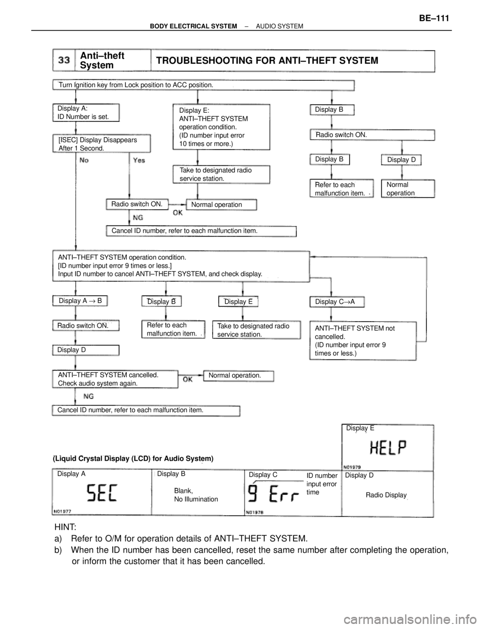
Display E:
ANTI±THEFT SYSTEM
operation condition.
(ID number input error
10 times or more.)Display A:
ID Number is set.Display B
Anti±theft
SystemTROUBLESHOOTING FOR ANTI±THEFT SYSTEM
Turn Ignition key from Lock position to ACC position.
Cancel ID number, refer to each malfunction item.
Take to designated radio
service station.
[ISEC] Display Disappears
After 1 Second.
Normal operation
Refer to each
malfunction item.
(Liquid Crystal Display (LCD) for Audio System)
Cancel ID number, refer to each malfunction item.
ANTI±THEFT SYSTEM operation condition.
[ID number input error 9 times or less.]
Input ID number to cancel ANTI±THEFT SYSTEM, and check display.
Radio switch ON.
ANTI±THEFT SYSTEM not
cancelled.
(ID number input error 9
times or less.)
ANTI±THEFT SYSTEM cancelled.
Check audio system again.
Radio Display
Display BDisplay D
Radio switch ON.
Display EDisplay C"ADisplay BDisplay A " B
Display D
Radio switch ON.Take to designated radio
service station.Refer to each
malfunction item.
Normal
operation
Normal operation.
ID number
input error
time
Blank,
No Illumination
Display B
Display E
Display DDisplay ADisplay C
HINT:
a) Refer to O/M for operation details of ANTI±THEFT SYSTEM.
b) When the ID number has been cancelled, reset the same number after completing the operation,
or inform the customer that it has been cancelled.
± BODY ELECTRICAL SYSTEMAUDIO SYSTEMBE±111
Page 714 of 2543

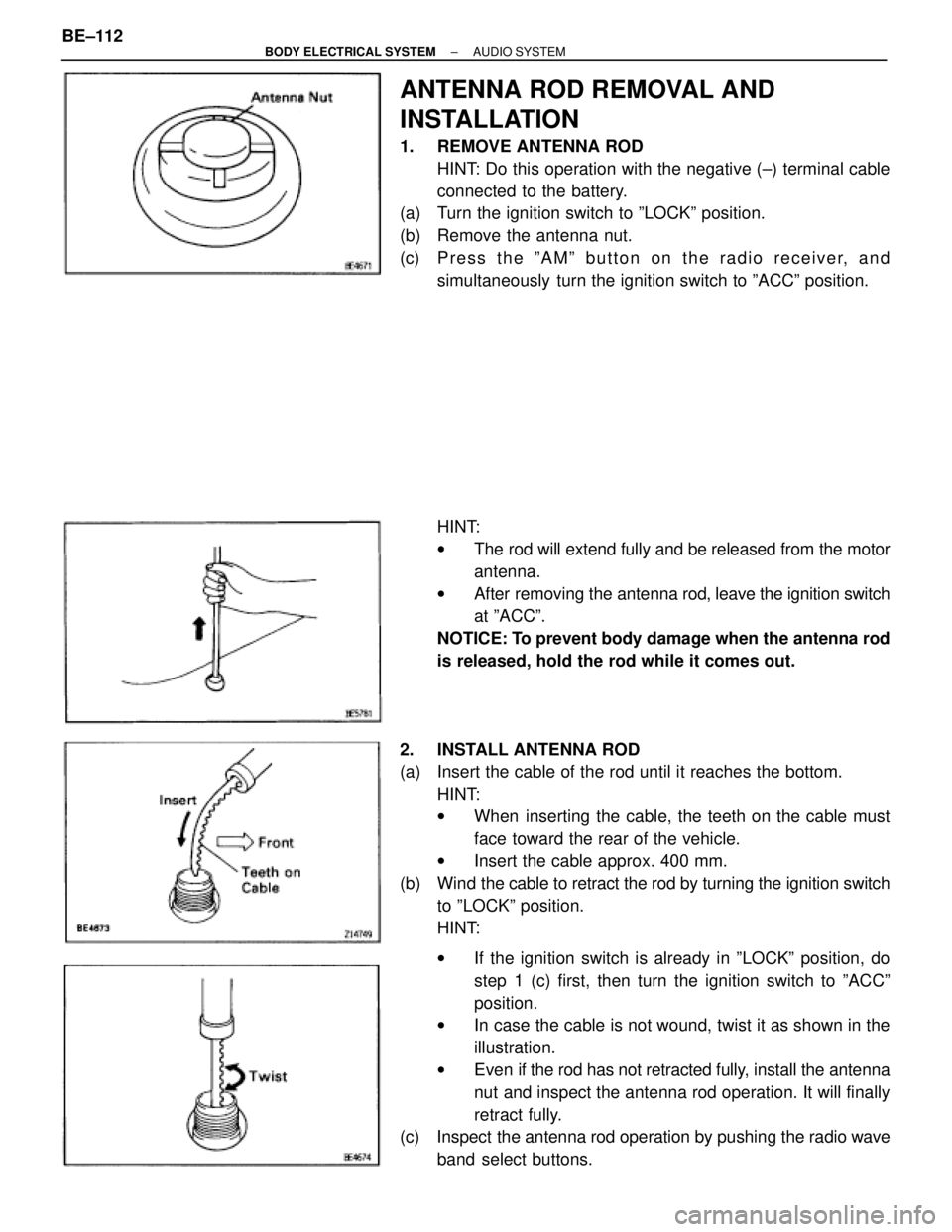
ANTENNA ROD REMOVAL AND
INSTALLATION
1. REMOVE ANTENNA ROD
HINT: Do this operation with the negative (±) terminal cable
connected to the battery.
(a) Turn the ignition switch to ºLOCKº position.
(b) Remove the antenna nut.
(c) P r e s s t h e º A M º b u t t o n o n t h e r a d i o r e c e i v e r, a n d
simultaneously turn the ignition switch to ºACCº position.
HINT:
wThe rod will extend fully and be released from the motor
antenna.
wAfter removing the antenna rod, leave the ignition switch
at ºACCº.
NOTICE: To prevent body damage when the antenna rod
is released, hold the rod while it comes out.
2. INSTALL ANTENNA ROD
(a) Insert the cable of the rod until it reaches the bottom.
HINT:
wWhen inserting the cable, the teeth on the cable must
face toward the rear of the vehicle.
wInsert the cable approx. 400 mm.
(b) Wind the cable to retract the rod by turning the ignition switch
to ºLOCKº position.
HINT:
wIf the ignition switch is already in ºLOCKº position, do
step 1 (c) first, then turn the ignition switch to ºACCº
position.
wIn case the cable is not wound, twist it as shown in the
illustration.
wEven if the rod has not retracted fully, install the antenna
nut and inspect the antenna rod operation. It will finally
retract fully.
(c) Inspect the antenna rod operation by pushing the radio wave
band select buttons. BE±112
± BODY ELECTRICAL SYSTEMAUDIO SYSTEM
Page 715 of 2543

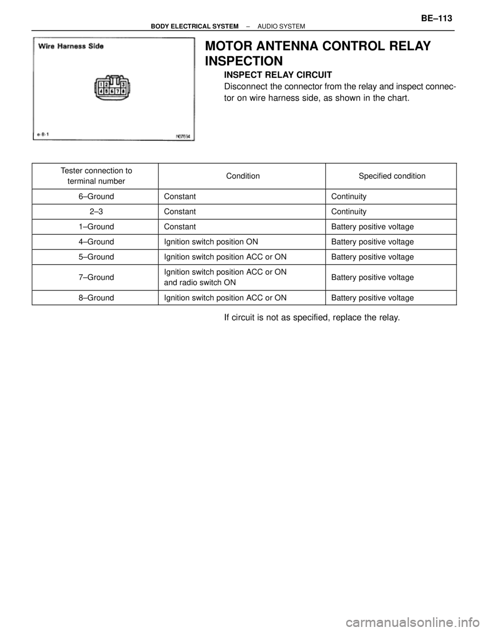
MOTOR ANTENNA CONTROL RELAY
INSPECTION
INSPECT RELAY CIRCUIT
Disconnect the connector from the relay and inspect connec-
tor on wire harness side, as shown in the chart.
����������� �
���������� �����������
Tester connection to
terminal number��������������� �
�������������� ���������������Condition������������ �
����������� ������������Specified condition
����������� �����������6±Ground��������������� ���������������Constant������������ ������������Continuity
����������� �����������2±3��������������� ���������������Constant������������ ������������Continuity����������� �
���������� �����������1±Ground
��������������� �
�������������� ���������������Constant
������������ �
����������� ������������Battery positive voltage
����������� �����������4±Ground��������������� ���������������Ignition switch position ON������������ ������������Battery positive voltage
����������� �����������5±Ground��������������� ���������������Ignition switch position ACC or ON������������ ������������Battery positive voltage
����������� �
���������� �����������7±Ground
��������������� �
�������������� ���������������Ignition switch position ACC or ON
and radio switch ON������������ �
����������� ������������Battery positive voltage
����������� �����������8±Ground��������������� ���������������Ignition switch position ACC or ON������������ ������������Battery positive voltage
If circuit is not as specified, replace the relay.
± BODY ELECTRICAL SYSTEMAUDIO SYSTEMBE±113
Page 805 of 2543
��������������������� ��������������������� ANTENNA MOTOR CONTROL RELAY (Wire Harness Side)���������������� ����������������
��������������������� ��������������������� 1 ± Ground (Constant)���������������� ����������������Battery positive voltage
��������������������� ��������������������� 4 ± Ground (Ignition SW position ON)���������������� ����������������Battery positive voltage��������������������� �
�������������������� ��������������������� 5 ± Ground (Ignition SW position ACC or ON)
���������������� �
��������������� ����������������Battery positive voltage
��������������������� ��������������������� 7 ± Ground (Ignition SW position ACC or ON and radio SW ON)���������������� ����������������Battery positive voltage
��������������������� ��������������������� 8 ± Ground (Ignition SW position ACC or ON)���������������� ����������������Battery positive voltage
± BODY ELECTRICAL SYSTEMSERVICE SPECIFICATIONSBE±203