Page 1846 of 2543

DIFFERENTIAL REMOVAL
Installation is in the reverse order of removal.
1. DRAIN DIFFERENTIAL OIL
2. REMOVE PROPELLER SHAFT
(See page PR±5)
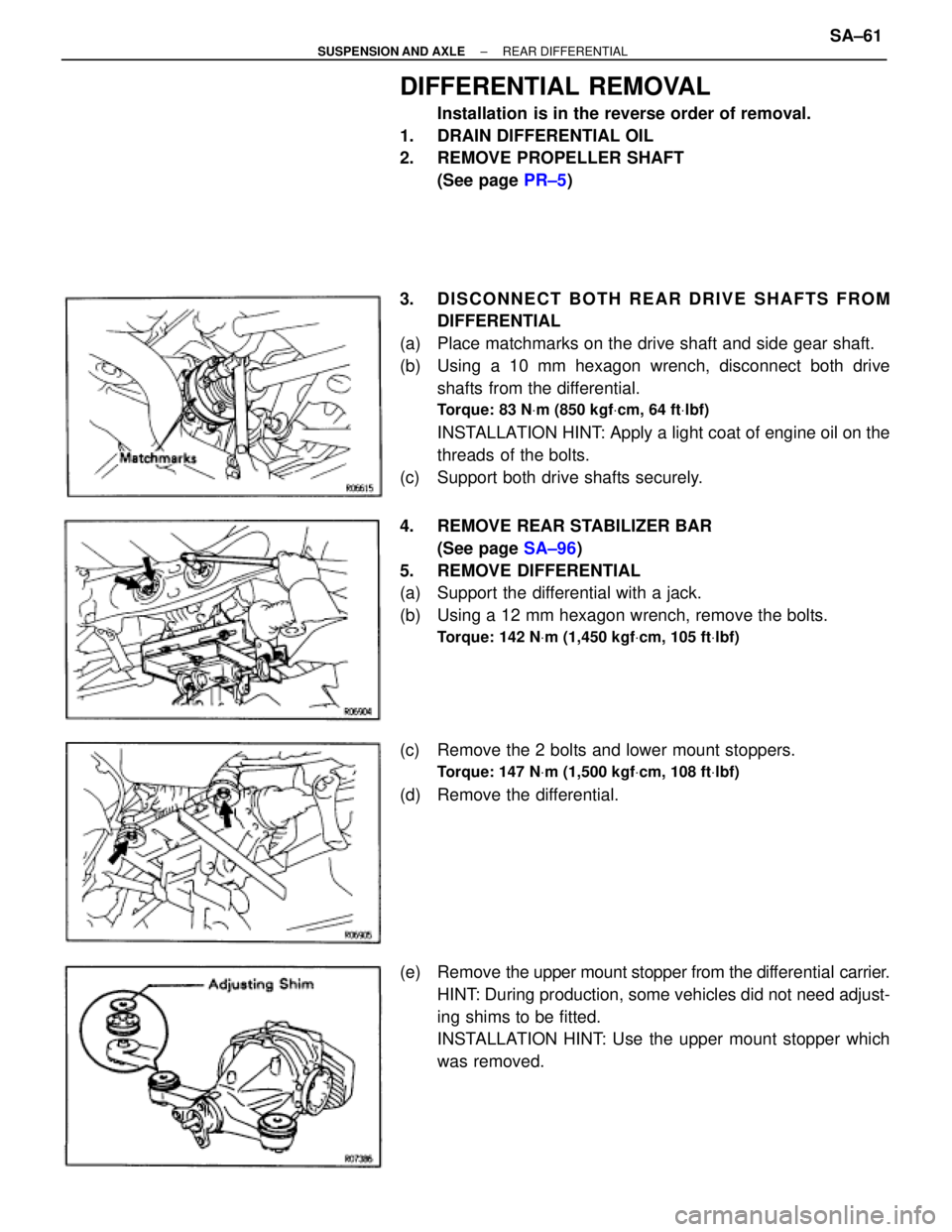
3. DISCONNECT BOTH REAR DRIVE SHAFTS FROM
DIFFERENTIAL
(a) Place matchmarks on the drive shaft and side gear shaft.
(b) Using a 10 mm hexagon wrench, disconnect both drive
shafts from the differential.
Torque: 83 NVm (850 kgfVcm, 64 ftVlbf)
INSTALLATION HINT: Apply a light coat of engine oil on the
threads of the bolts.
(c) Support both drive shafts securely.
4. REMOVE REAR STABILIZER BAR
(See page SA±96)
5. REMOVE DIFFERENTIAL
(a) Support the differential with a jack.
(b) Using a 12 mm hexagon wrench, remove the bolts.
Torque: 142 NVm (1,450 kgfVcm, 105 ftVlbf)
(c) Remove the 2 bolts and lower mount stoppers.
Torque: 147 NVm (1,500 kgfVcm, 108 ftVlbf)
(d) Remove the differential.
(e) Remove the upper mount stopper from the differential carrier.
HINT: During production, some vehicles did not need adjust-
ing shims to be fitted.
INSTALLATION HINT: Use the upper mount stopper which
was removed.
± SUSPENSION AND AXLEREAR DIFFERENTIALSA±61
Page 1847 of 2543
DIFFERENTIAL CARRIER
COMPONENTS
SA±62± SUSPENSION AND AXLEREAR DIFFERENTIAL
Page 1848 of 2543
± SUSPENSION AND AXLEREAR DIFFERENTIALSA±63
Page 1849 of 2543

DIFFERENTIAL CARRIER INSPECTION
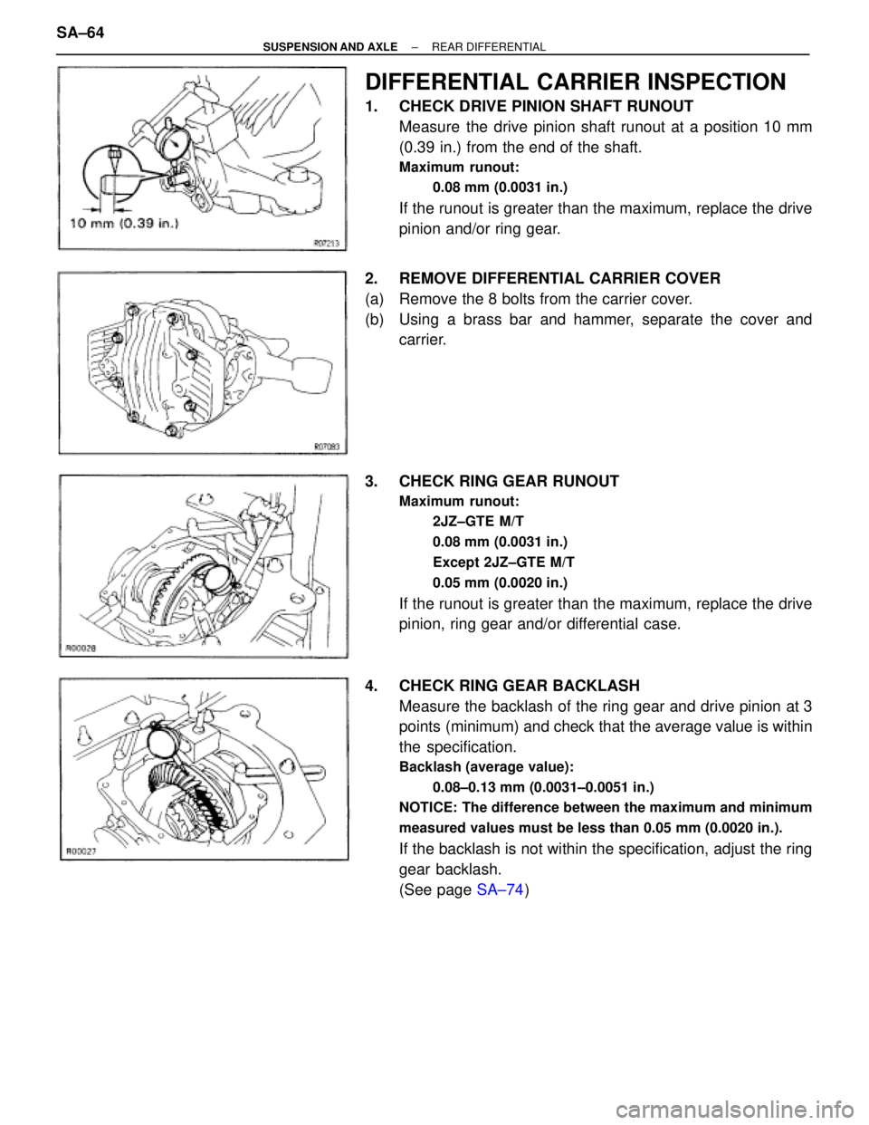
1. CHECK DRIVE PINION SHAFT RUNOUT
Measure the drive pinion shaft runout at a position 10 mm
(0.39 in.) from the end of the shaft.
Maximum runout:
0.08 mm (0.0031 in.)
If the runout is greater than the maximum, replace the drive
pinion and/or ring gear.
2. REMOVE DIFFERENTIAL CARRIER COVER
(a) Remove the 8 bolts from the carrier cover.
(b) Using a brass bar and hammer, separate the cover and
carrier.
3. CHECK RING GEAR RUNOUT
Maximum runout:
2JZ±GTE M/T
0.08 mm (0.0031 in.)
Except 2JZ±GTE M/T
0.05 mm (0.0020 in.)
If the runout is greater than the maximum, replace the drive
pinion, ring gear and/or differential case.
4. CHECK RING GEAR BACKLASH
Measure the backlash of the ring gear and drive pinion at 3
points (minimum) and check that the average value is within
the specification.
Backlash (average value):
0.08±0.13 mm (0.0031±0.0051 in.)
NOTICE: The difference between the maximum and minimum
measured values must be less than 0.05 mm (0.0020 in.).
If the backlash is not within the specification, adjust the ring
gear backlash.
(See page SA±74) SA±64
± SUSPENSION AND AXLEREAR DIFFERENTIAL
Page 1850 of 2543

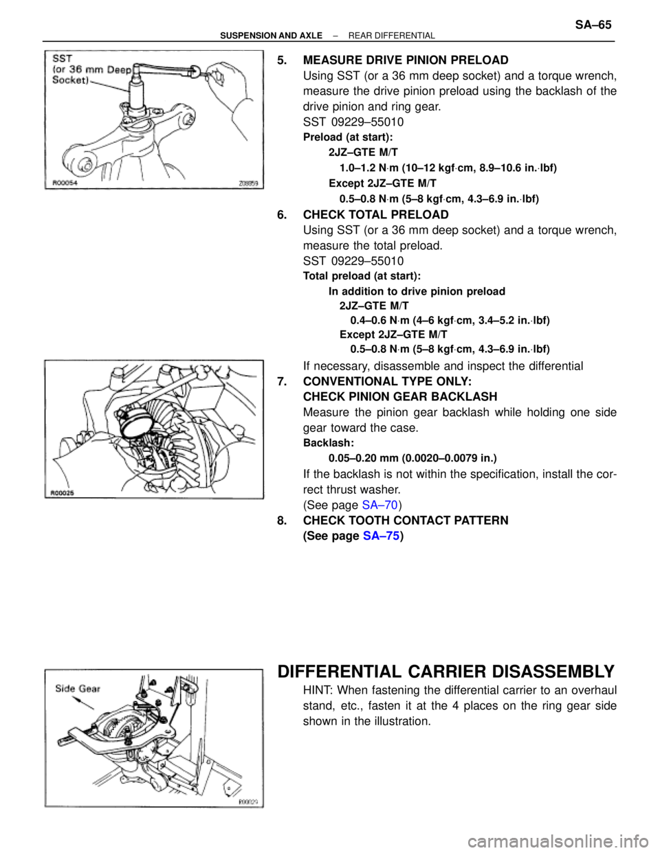
5. MEASURE DRIVE PINION PRELOAD
Using SST (or a 36 mm deep socket) and a torque wrench,
measure the drive pinion preload using the backlash of the
drive pinion and ring gear.
SST 09229±55010
Preload (at start):
2JZ±GTE M/T
1.0±1.2 NVm (10±12 kgfVcm, 8.9±10.6 in.Vlbf)
Except 2JZ±GTE M/T
0.5±0.8 NVm (5±8 kgfVcm, 4.3±6.9 in.Vlbf)
6. CHECK TOTAL PRELOAD
Using SST (or a 36 mm deep socket) and a torque wrench,
measure the total preload.
SST 09229±55010
Total preload (at start):
In addition to drive pinion preload
2JZ±GTE M/T
0.4±0.6 NVm (4±6 kgfVcm, 3.4±5.2 in.Vlbf)
Except 2JZ±GTE M/T
0.5±0.8 NVm (5±8 kgfVcm, 4.3±6.9 in.Vlbf)
If necessary, disassemble and inspect the differential
7. CONVENTIONAL TYPE ONLY:
CHECK PINION GEAR BACKLASH
Measure the pinion gear backlash while holding one side
gear toward the case.
Backlash:
0.05±0.20 mm (0.0020±0.0079 in.)
If the backlash is not within the specification, install the cor-
rect thrust washer.
(See page SA±70)
8. CHECK TOOTH CONTACT PATTERN
(See page SA±75)
DIFFERENTIAL CARRIER DISASSEMBLY
HINT: When fastening the differential carrier to an overhaul
stand, etc., fasten it at the 4 places on the ring gear side
shown in the illustration.
± SUSPENSION AND AXLEREAR DIFFERENTIALSA±65
Page 1851 of 2543
1. REMOVE SIDE GEAR SHAFT
(a) 2JZ±GTE M/T only:
Equally tighten both bolts at the same time and pull out the
side gear shaft.
NOTICE: Pull out the side gear shaft until a nut can fit be-
hind the shaft. Pulling the shaft out too far will damage
the dust cover.
(b) Using SST and 2 bolts, nuts, remove the side gear shaft.
SST 09520±24010
(c) Using a screwdriver, remove the snap ring from the side gear
shaft.
2. REMOVE SIDE GEAR SHAFT OIL SEALS
Using SST, remove the oil seal.
SST 09308±00010
3. REMOVE DIFFERENTIAL CARRIER RETAINER (AND
ADJUSTING PLATE WASHER)
(a) Remove the 8 bolts.
(b) 2JZ±GTE M/T:
Using SST, remove the carrier retainer and adjusting plate
washer.
SST 09550±10012 (09558±10010),
09950±40010
Except 2JZ±GTE M/T:
Using 2 screwdrivers, remove the carrier retainer.
(c) Using a screwdriver, remove the O±ring from the carrier
retainer. SA±66
± SUSPENSION AND AXLEREAR DIFFERENTIAL
Page 1852 of 2543
4. REMOVE DIFFERENTIAL CASE
Take the differential case out of the carrier while lifting the ring
gear side, as shown in the illustration.
5. REMOVE SIDE BEARING OUTER RACE (AND
ADJUSTING PLATE WASHER)
2JZ±GTE M/T:
Using a brass bar and hammer, drive out the outer race.
Except 2JZ±GTE M/T:
Using SST and a press, press out the outer race and adjust-
ing plate washer.
SST 09608±35014 (09608±06020, 09608±06110)
6. REMOVE DRIVE PINION, (OIL SLINGER), SPACER AND
COMPANION FLANGE
(a) Using a hammer and chisel, loosen the staked part of the nut.
(b) Using SST (and a 36 mm deep socket wrench), remove the
nut.
SST 09229±55010 (Except 2JZ±GTE M/T only),
09330±00021
(c) Using a press, press out the drive pinion with the rear bearing
and spacer.
NOTICE: Be careful not to drop the drive pinion.
(d) Remove the companion flange.
(e) Remove the oil slinger (2JZ±GTE M/T only) and spacer from
the drive pinion.
± SUSPENSION AND AXLEREAR DIFFERENTIALSA±67
Page 1853 of 2543

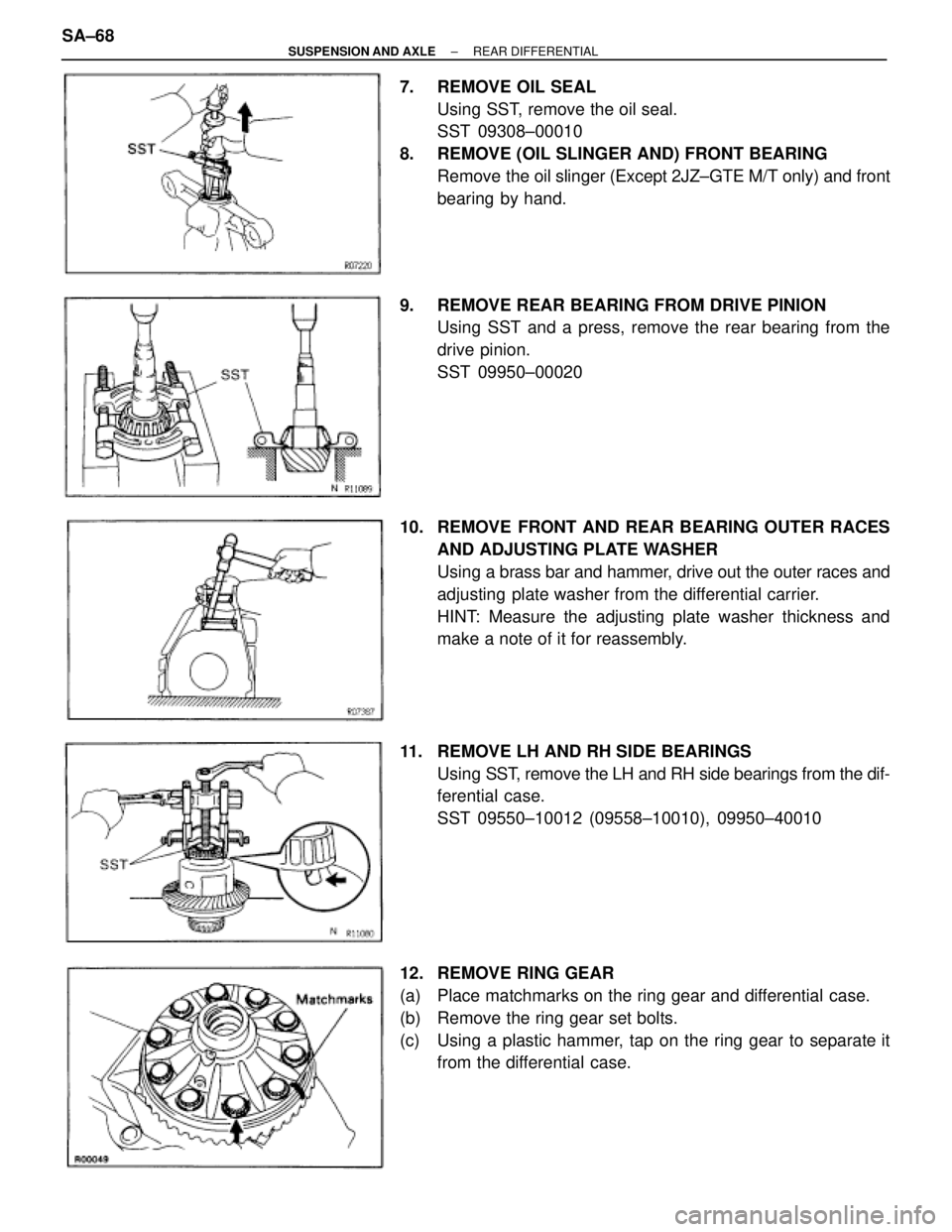
7. REMOVE OIL SEAL
Using SST, remove the oil seal.
SST 09308±00010
8. REMOVE (OIL SLINGER AND) FRONT BEARING
Remove the oil slinger (Except 2JZ±GTE M/T only) and front
bearing by hand.
9. REMOVE REAR BEARING FROM DRIVE PINION
Using SST and a press, remove the rear bearing from the
drive pinion.
SST 09950±00020
10. REMOVE FRONT AND REAR BEARING OUTER RACES
AND ADJUSTING PLATE WASHER
Using a brass bar and hammer, drive out the outer races and
adjusting plate washer from the differential carrier.
HINT: Measure the adjusting plate washer thickness and
make a note of it for reassembly.
11. REMOVE LH AND RH SIDE BEARINGS
Using SST, remove the LH and RH side bearings from the dif-
ferential case.
SST 09550±10012 (09558±10010), 09950±40010
12. REMOVE RING GEAR
(a) Place matchmarks on the ring gear and differential case.
(b) Remove the ring gear set bolts.
(c) Using a plastic hammer, tap on the ring gear to separate it
from the differential case. SA±68
± SUSPENSION AND AXLEREAR DIFFERENTIAL