Page 1323 of 2543
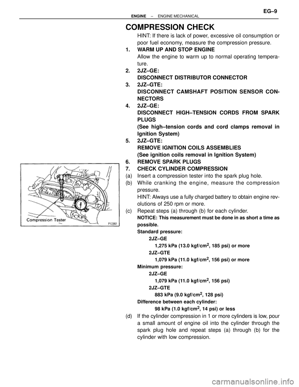
COMPRESSION CHECK
HINT: If there is lack of power, excessive oil consumption or
poor fuel economy, measure the compression pressure.
1. WARM UP AND STOP ENGINE
Allow the engine to warm up to normal operating tempera-
ture.
2. 2JZ±GE:
DISCONNECT DISTRIBUTOR CONNECTOR
3. 2JZ±GTE:
DISCONNECT CAMSHAFT POSITION SENSOR CON-
NECTORS
4. 2JZ±GE:
DISCONNECT HIGH±TENSION CORDS FROM SPARK
PLUGS
(See high±tension cords and cord clamps removal in
Ignition System)
5. 2JZ±GTE:
REMOVE IGNITION COILS ASSEMBLIES
(See ignition coils removal in Ignition System)
6. REMOVE SPARK PLUGS
7. CHECK CYLINDER COMPRESSION
(a) Insert a compression tester into the spark plug hole.
(b) Wh ile cra n kin g th e en g in e , me a su re th e co mp re ssio n
pressure.
HINT: Always use a fully charged battery to obtain engine rev-
olutions of 250 rpm or more.
(c) Repeat steps (a) through (b) for each cylinder.
NOTICE: This measurement must be done in as short a time as
possible.
Standard pressure:
2JZ±GE
1,275 kPa (13.0 kgf/cm
2, 185 psi) or more
2JZ±GTE
1,079 kPa (11.0 kgf/cm
2, 156 psi) or more
Minimum pressure:
2JZ±GE
1,079 kPa (11.0 kgf/cm
2, 156 psi)
2JZ±GTE
883 kPa (9.0 kgf/cm
2, 128 psi)
Difference between each cylinder:
98 kPa (1.0 kgf/cm
2, 14 psi) or less
(d) If the cylinder compression in 1 or more cylinders is low, pour
a small amount of engine oil into the cylinder through the
spark plug hole and repeat steps (a) through (b) for the
cylinder with low compression.
± ENGINEENGINE MECHANICALEG±9
Page 1356 of 2543
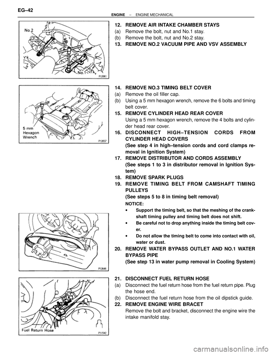
12. REMOVE AIR INTAKE CHAMBER STAYS
(a) Remove the bolt, nut and No.1 stay.
(b) Remove the bolt, nut and No.2 stay.
13. REMOVE NO.2 VACUUM PIPE AND VSV ASSEMBLY
14. REMOVE NO.3 TIMING BELT COVER
(a) Remove the oil filler cap.
(b) Using a 5 mm hexagon wrench, remove the 6 bolts and timing
belt cover.
15. REMOVE CYLINDER HEAD REAR COVER
Using a 5 mm hexagon wrench, remove the 4 bolts and cylin-
der head rear cover.
16. D I S C O N N E C T H I G H ± T E N S I O N C O R D S F R O M
CYLINDER HEAD COVERS
(See step 4 in high±tension cords and cord clamps re-
moval in Ignition System)
17. REMOVE DISTRIBUTOR AND CORDS ASSEMBLY
(See steps 1 to 3 in distributor removal in Ignition Sys-
tem)
18. REMOVE SPARK PLUGS
19. RE MO V E TIMING BE LT FRO M CAMS HAFT TIMING
PULLEYS
(See steps 5 to 8 in timing belt removal)
NOTICE:
wSupport the timing belt, so that the meshing of the crank-
shaft timing pulley and timing belt does not shift.
wBe careful not to drop anything inside the timing belt cov-
er.
wDo not allow the timing belt to come into contact with oil,
water or dust.
20. REMOVE WATER BYPASS OUTLET AND NO.1 WATER
BYPASS PIPE
(See step 13 in water pump removal in Cooling System)
21. DISCONNECT FUEL RETURN HOSE
(a) Disconnect the fuel return hose from the fuel return pipe. Plug
the hose end.
(b) Disconnect the fuel return hose from the oil dipstick guide.
22. REMOVE ENGINE WIRE BRACET
Remove the bolt and bracket, disconnect the engine wire the
intake manifold stay. EG±42
± ENGINEENGINE MECHANICAL
Page 1357 of 2543
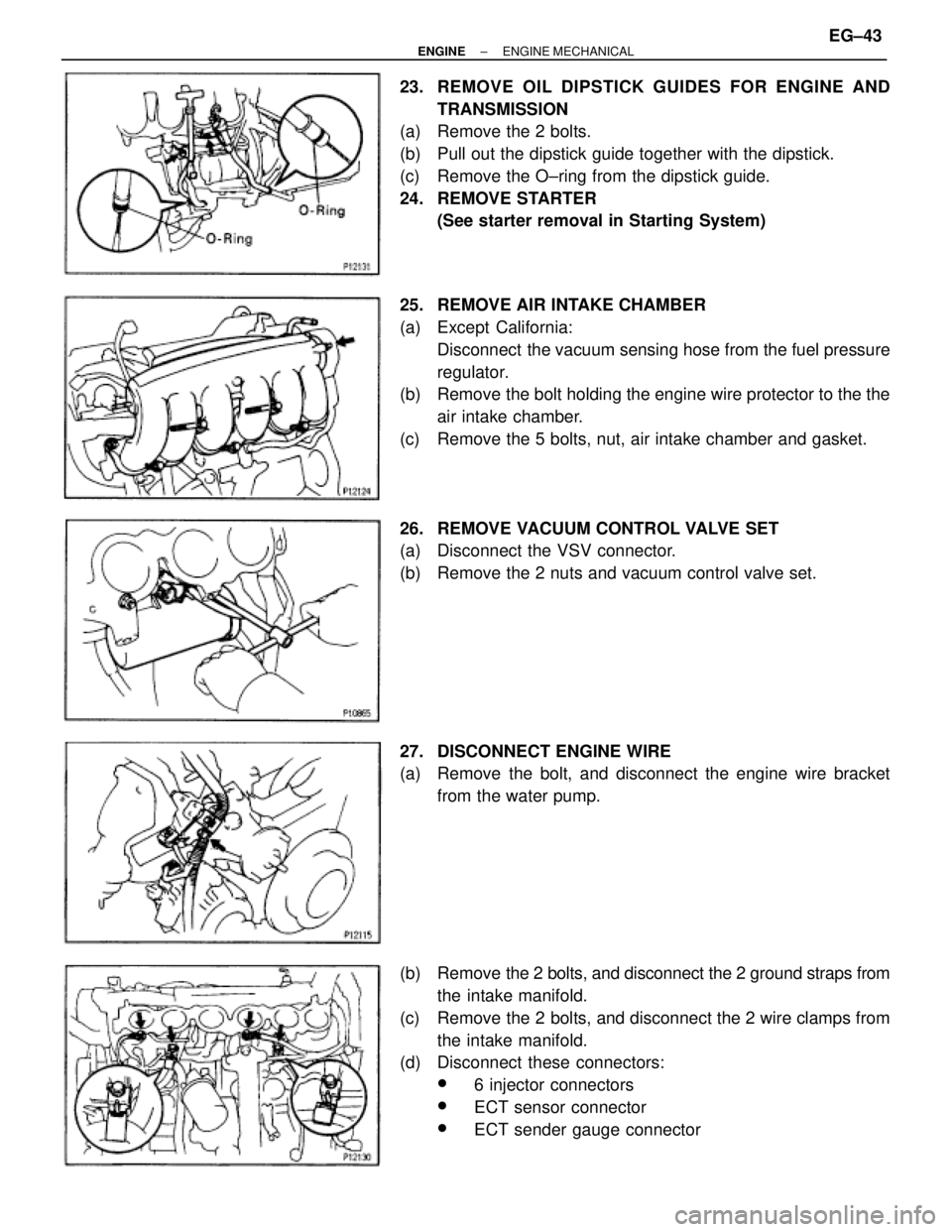
23. REMOVE OIL DIPSTICK GUIDES FOR ENGINE AND
TRANSMISSION
(a) Remove the 2 bolts.
(b) Pull out the dipstick guide together with the dipstick.
(c) Remove the O±ring from the dipstick guide.
24. REMOVE STARTER
(See starter removal in Starting System)
25. REMOVE AIR INTAKE CHAMBER
(a) Except California:
Disconnect the vacuum sensing hose from the fuel pressure
regulator.
(b) Remove the bolt holding the engine wire protector to the the
air intake chamber.
(c) Remove the 5 bolts, nut, air intake chamber and gasket.
26. REMOVE VACUUM CONTROL VALVE SET
(a) Disconnect the VSV connector.
(b) Remove the 2 nuts and vacuum control valve set.
27. DISCONNECT ENGINE WIRE
(a) Remove the bolt, and disconnect the engine wire bracket
from the water pump.
(b) Remove the 2 bolts, and disconnect the 2 ground straps from
the intake manifold.
(c) Remove the 2 bolts, and disconnect the 2 wire clamps from
the intake manifold.
(d) Disconnect these connectors:
w6 injector connectors
wECT sensor connector
wECT sender gauge connector
± ENGINEENGINE MECHANICALEG±43
Page 1358 of 2543
(e) Remove the 3 nuts, and disconnect the engine wire protector
from the intake manifold.
28. REMOVE WATER OUTLET AND NO.1 BYPASS HOSE
ASSEMBLY
Remove the 2 nuts, bolt and water outlet.
29. REMOVE INTAKE MANIFOLD STAY
Remove the 2 bolts and manifold stay.
30. REMOVE FUEL PRESSURE PULSATION DAMPER
(See step 2 in fuel pressure pulsation damper in SFI Sys-
tem)
31. REMOVE FUEL INLET PIPE
(a) Remove the clamp bolt from the intake manifold.
(b) Remove the union bolt and 2 gaskets, and disconnect the
fuel inlet pipe.
32. RE MO V E INTAKE MANIFO LD AND DE LIV E RY PIP E
ASSEMBLY
Remove the 6 bolts, 2 nuts, the intake manifold, delivery pipe
assembly and gasket. EG±44
± ENGINEENGINE MECHANICAL
Page 1361 of 2543
4. REMOVE DRIVE BELT
Loosen the drive belt tension by turning the drive belt tension-
er clockwise, and remove the drive belt.
5. REMOVE WATER OUTLET AND NO.1 WATER BYPASS
PIPE
(a) Disconnect the upper radiator hose from the water outlet.
(b) Disconnect the ECT sensor and sender gauge connectors.
(c) Remove the 2 bolts, water outlet and gasket.
(d) Remove the No.1 water bypass pipe and 2 O±rings.
6. DISCONNECT PS PUMP WITHOUT DISCONNECTING
HOSES
(a) Disconnect these hoses:
(1) Air hose from throttle body
(2) Air hose from air intake chamber
(b) Remove the 2 bolts, and disconnect the pump housing from
the pump bracket.
HINT: Put aside the pump housing, and suspend it securely.
7. DISCONNECT FUEL RETURN HOSE
Disconnect the fuel return hose from the fuel return pipe. Plug
the hose end.
8. REMOVE AIR INTAKE CHAMBER ASSEMBLY
(See injector removal in SFI System)
± ENGINEENGINE MECHANICALEG±47
Page 1362 of 2543
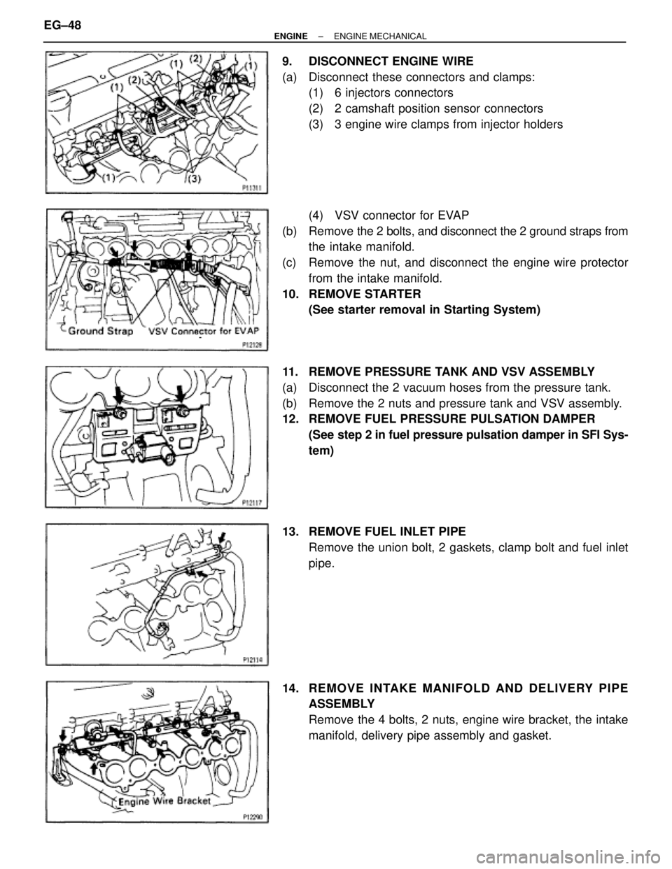
9. DISCONNECT ENGINE WIRE
(a) Disconnect these connectors and clamps:
(1) 6 injectors connectors
(2) 2 camshaft position sensor connectors
(3) 3 engine wire clamps from injector holders
(4) VSV connector for EVAP
(b) Remove the 2 bolts, and disconnect the 2 ground straps from
the intake manifold.
(c) Remove the nut, and disconnect the engine wire protector
from the intake manifold.
10. REMOVE STARTER
(See starter removal in Starting System)
11. REMOVE PRESSURE TANK AND VSV ASSEMBLY
(a) Disconnect the 2 vacuum hoses from the pressure tank.
(b) Remove the 2 nuts and pressure tank and VSV assembly.
12. REMOVE FUEL PRESSURE PULSATION DAMPER
(See step 2 in fuel pressure pulsation damper in SFI Sys-
tem)
13. REMOVE FUEL INLET PIPE
Remove the union bolt, 2 gaskets, clamp bolt and fuel inlet
pipe.
14. RE MO V E INTAKE MANIFO LD AND DE LIV E RY PIP E
ASSEMBLY
Remove the 4 bolts, 2 nuts, engine wire bracket, the intake
manifold, delivery pipe assembly and gasket. EG±48
± ENGINEENGINE MECHANICAL
Page 1381 of 2543
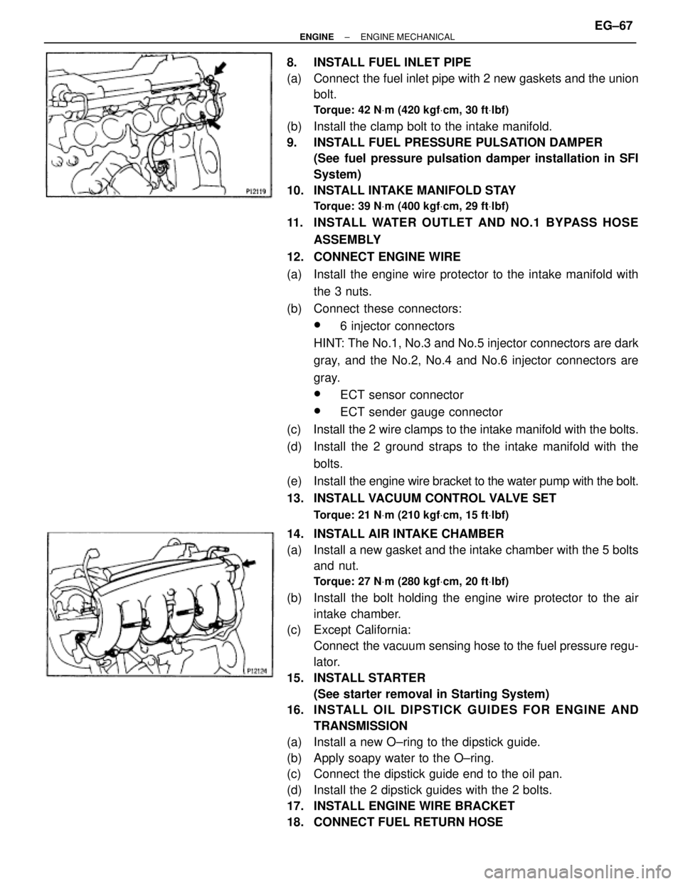
8. INSTALL FUEL INLET PIPE
(a) Connect the fuel inlet pipe with 2 new gaskets and the union
bolt.
Torque: 42 NVm (420 kgfVcm, 30 ftVlbf)
(b) Install the clamp bolt to the intake manifold.
9. INSTALL FUEL PRESSURE PULSATION DAMPER
(See fuel pressure pulsation damper installation in SFI
System)
10. INSTALL INTAKE MANIFOLD STAY
Torque: 39 NVm (400 kgfVcm, 29 ftVlbf)
11. INSTALL WATER OUTLET AND NO.1 BYPASS HOSE
ASSEMBLY
12. CONNECT ENGINE WIRE
(a) Install the engine wire protector to the intake manifold with
the 3 nuts.
(b) Connect these connectors:
w6 injector connectors
HINT: The No.1, No.3 and No.5 injector connectors are dark
gray, and the No.2, No.4 and No.6 injector connectors are
gray.
wECT sensor connector
wECT sender gauge connector
(c) Install the 2 wire clamps to the intake manifold with the bolts.
(d) Install the 2 ground straps to the intake manifold with the
bolts.
(e) Install the engine wire bracket to the water pump with the bolt.
13. INSTALL VACUUM CONTROL VALVE SET
Torque: 21 NVm (210 kgfVcm, 15 ftVlbf)
14. INSTALL AIR INTAKE CHAMBER
(a) Install a new gasket and the intake chamber with the 5 bolts
and nut.
Torque: 27 NVm (280 kgfVcm, 20 ftVlbf)
(b) Install the bolt holding the engine wire protector to the air
intake chamber.
(c) Except California:
Connect the vacuum sensing hose to the fuel pressure regu-
lator.
15. INSTALL STARTER
(See starter removal in Starting System)
16. INS TALL OIL DIP S TICK GUIDE S FO R ENG INE AND
TRANSMISSION
(a) Install a new O±ring to the dipstick guide.
(b) Apply soapy water to the O±ring.
(c) Connect the dipstick guide end to the oil pan.
(d) Install the 2 dipstick guides with the 2 bolts.
17. INSTALL ENGINE WIRE BRACKET
18. CONNECT FUEL RETURN HOSE
± ENGINEENGINE MECHANICALEG±67
Page 1384 of 2543
(d) Install the seal washers to the mounting bolts.
(e) Install the No.2 cylinder head cover with the 4 seal washers
and 4 bolts.
Torque: 5.4 NVm (55 kgfVcm, 48 in.Vlbf)
(f) Install the No.1 cylinder head cover with the 4 seal washers
and 4 bolts.
Torque: 5.4 NVm (55 kgfVcm, 48 in.Vlbf)
(g) Install the PCV valve.
(h) Install the cruise control actuator cable bracket and IAC valve
pipe clamp with the 2 bolts.
7. INSTALL SPARK PLUGS
8. INSTALL IGNITION COILS ASSEMBLIES
(See ignition coils installation in Ignition System)
9. INSTALL TIMING BELT
(See steps 11 to 17 in timing belt installation)
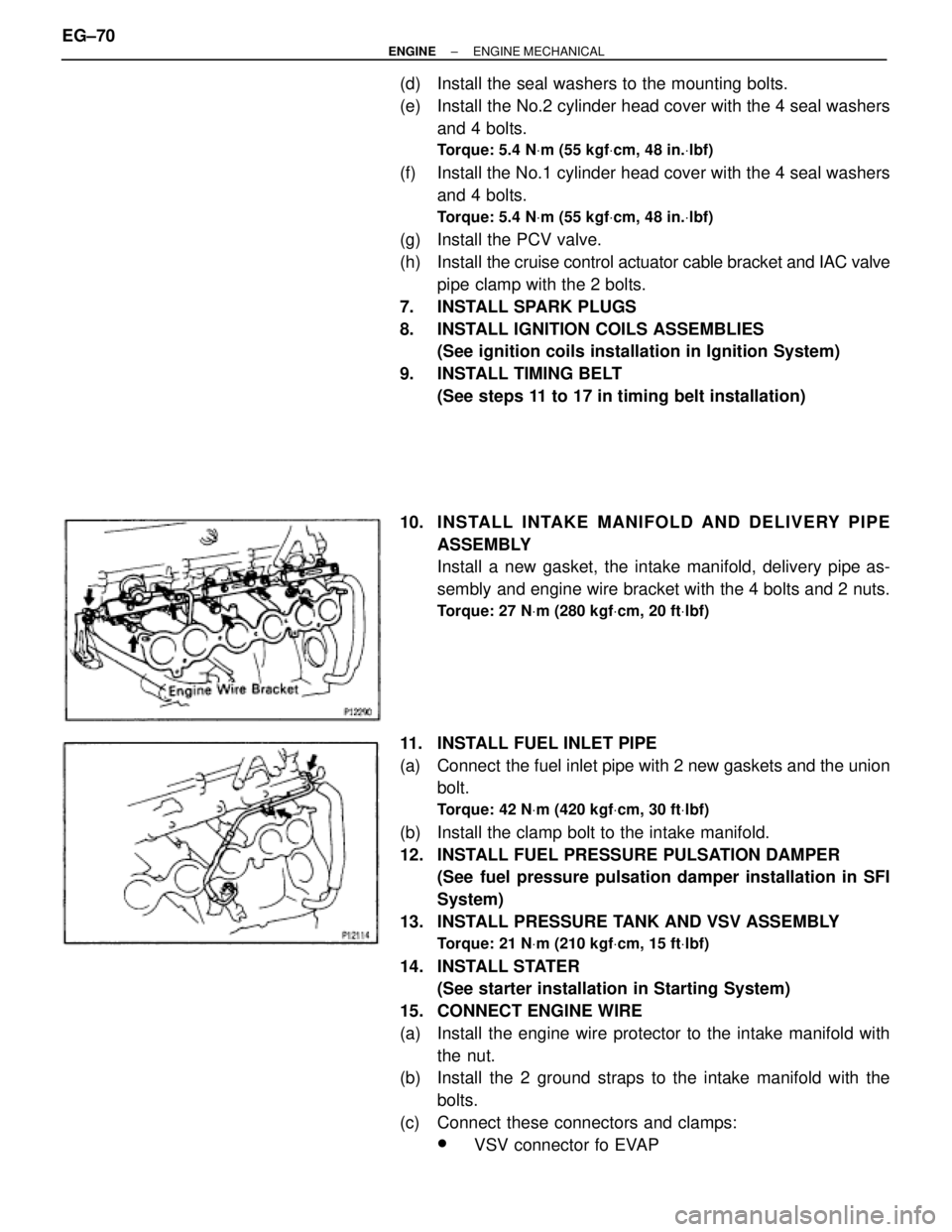
10. INS TALL INTAKE MANIFO LD AND DE LIV E RY PIP E
ASSEMBLY
Install a new gasket, the intake manifold, delivery pipe as-
sembly and engine wire bracket with the 4 bolts and 2 nuts.
Torque: 27 NVm (280 kgfVcm, 20 ftVlbf)
11. INSTALL FUEL INLET PIPE
(a) Connect the fuel inlet pipe with 2 new gaskets and the union
bolt.
Torque: 42 NVm (420 kgfVcm, 30 ftVlbf)
(b) Install the clamp bolt to the intake manifold.
12. INSTALL FUEL PRESSURE PULSATION DAMPER
(See fuel pressure pulsation damper installation in SFI
System)
13. INSTALL PRESSURE TANK AND VSV ASSEMBLY
Torque: 21 NVm (210 kgfVcm, 15 ftVlbf)
14. INSTALL STATER
(See starter installation in Starting System)
15. CONNECT ENGINE WIRE
(a) Install the engine wire protector to the intake manifold with
the nut.
(b) Install the 2 ground straps to the intake manifold with the
bolts.
(c) Connect these connectors and clamps:
wVSV connector fo EVAP EG±70
± ENGINEENGINE MECHANICAL