Page 397 of 2543
����� �
���� �
���� �����
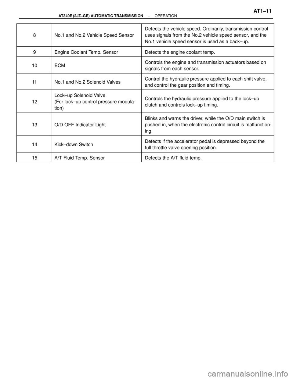
8
�������������� �
������������� �
������������� ��������������
No.1 and No.2 Vehicle Speed Sensor
������������������� �
������������������ �
������������������ �������������������
Detects the vehicle speed. Ordinarily, transmission control
uses signals from the No.2 vehicle speed sensor, and the
No.1 vehicle speed sensor is used as a back±up.
����� �����9Engine Coolant Temp SensorDetects the engine coolant temp����� �����9Engine Coolant Temp. SensorDetects the engine coolant temp.
����� �����
10ECMControls the engine and transmission actuators based on����� �����10ECMControls the engine and transmission actuators based on
signals from each sensor.����� �
���� �����11No 1 and No 2 Solenoid ValvesControl the hydraulic pressure applied to each shift valve,
����� �����11No.1 and No.2 Solenoid ValvesControl the hydraulic ressure a lied to each shift valve,
and control the gear position and timing.
����� �����
12
Lock±up Solenoid Valve
(For lock up control pressure modulaControls the hydraulic pressure applied to the lock±up����� �
���� �����
12(For lock±up control pressure modula-
tion)Controls the hydraulic ressure a lied to the lock u
clutch and controls lock±up timing.
����� �����
13O/D OFF Indicator Light
Blinks and warns the driver, while the O/D main switch is
pushed in when the electronic control circuit is malfunction����� �
���� �����
13O/D OFF Indicator Lightpushed in, when the electronic control circuit is malfunction-
ing.
����� �����
14Kick down SwitchDetects if the accelerator pedal is depressed beyond the����� �����14Kick±down SwitchDetects if the accelerator edal is de ressed beyond the
full throttle valve opening position.
����� �����
15A/T Fluid Temp SensorDetects the A/T fluid temp����� �����15A/T Fluid Temp. SensorDetects the A/T fluid temp.
± AT340E (2JZ±GE) AUTOMATIC TRANSMISSIONOPERATIONAT1±11
Page 398 of 2543
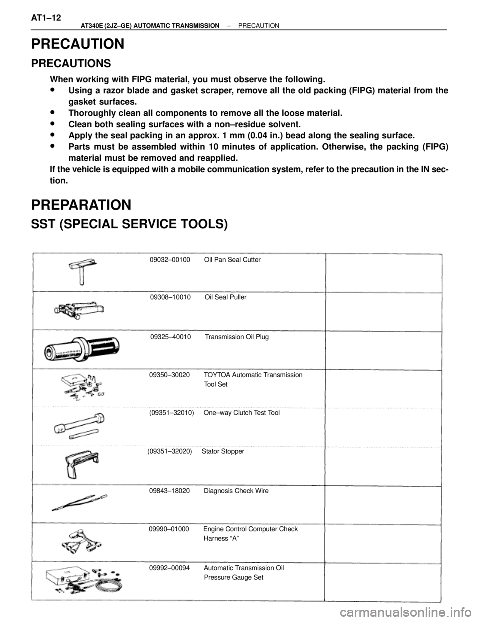
09032±00100 Oil Pan Seal Cutter
09308±10010 Oil Seal Puller
09325±40010 Transmission Oil Plug
09350±30020 TOYTOA Automatic Transmission
Tool Set
(09351±32010) One±way Clutch Test Tool
(09351±32020) Stator Stopper
09843±18020 Diagnosis Check Wire
09990±01000 Engine Control Computer Check
Harness ªAº
09992±00094 Automatic Transmission Oil
Pressure Gauge Set
PRECAUTION
PRECAUTIONS
When working with FIPG material, you must observe the following.
wUsing a razor blade and gasket scraper, remove all the old packing (FIPG) material from the
gasket surfaces.
wThoroughly clean all components to remove all the loose material.
wClean both sealing surfaces with a non±residue solvent.
wApply the seal packing in an approx. 1 mm (0.04 in.) bead along the sealing surface.
wParts must be assembled within 10 minutes of application. Otherwise, the packing (FIPG)
material must be removed and reapplied.
If the vehicle is equipped with a mobile communication system, refer to the precaution in the IN sec-
tion.
PREPARATION
SST (SPECIAL SERVICE TOOLS)
AT1±12± AT340E (2JZ±GE) AUTOMATIC TRANSMISSIONPRECAUTION
Page 399 of 2543
RECOMMENDED TOOLS
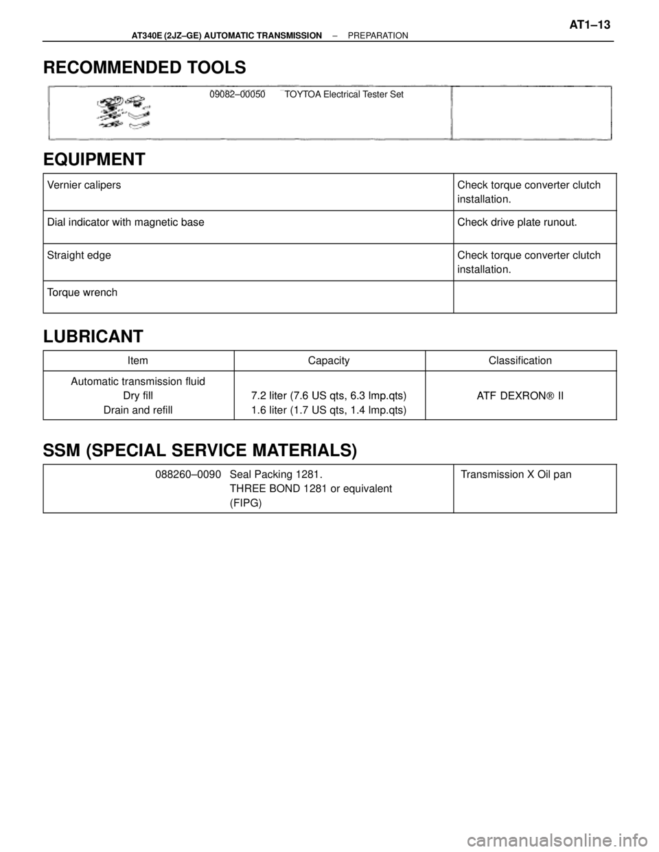
09082±00050 TOYTOA Electrical Tester Set
EQUIPMENT
�������������������������� �
������������������������� ��������������������������Vernier calipers����������� �
���������� �����������Check torque converter clutch
installation.
�������������������������� ��������������������������
Dial indicator with magnetic baseCheck drive plate runout.�������������������������� ��������������������������Dial indicator with magnetic baseCheck drive late runout.
�������������������������� �
������������������������� ��������������������������Straight edgeCheck torque converter clutch
installation.
�������������������������� ��������������������������
To rque wrench�������������������������� ��������������������������Torque wrench
LUBRICANT
������������� �������������Item������������ ������������Capacity������������� �������������Classification
������������� �������������Automatic transmission fluid
Dry fill7 2 liter (7 6 US qts 6 3 lmpqts)ATF DEXRON[II������������� �
������������ �������������
Dry fill
Drain and refill
7.2 liter (7.6 US qts, 6.3 lmp.qts)
1.6 liter (1.7 US qts, 1.4 lmp.qts)
ATF DEXRON[ II
SSM (SPECIAL SERVICE MATERIALS)
������������ �
����������� �
����������� ������������
088260±0090��������������� �
�������������� �
�������������� ���������������
Seal Packing 1281.
THREE BOND 1281 or equivalent
(FIPG)����������� �
���������� �
���������� �����������
Transmission X Oil pan
± AT340E (2JZ±GE) AUTOMATIC TRANSMISSIONPREPARATIONAT1±13
Page 405 of 2543
PARKING LOCK PAWL REMOVAL
Installation is in the reverse order of removal.
1. REMOVE VALVE BODY (See page AT1±16)
2. REMOVE PARKING LOCK PAWL BRACKET
INSTALLATION HINT:
w Push the lock rod fully forward.
w Install the 3 bolts finger tight.
w Check that the parking lock pawl operates smoothly.
Torque: 7.4 NVm (75 kgfVcm, 65 in.Vlbf)
3. REMOVE SPRING FROM PARKING LOCK PAWL SHAFT
4. REMOVE PARKING LOCK PAWL AND SHAFT
THROTTLE CABLE REPLACEMENT
1. DISCONNECT THROTTLE CABLE
(a) Disconnect the cable housing from the bracket.
(b) Disconnect the cable from the throttle linkage.
(c) Disconnect the cable from the torque converter clutch
housing.
± AT340E (2JZ±GE) AUTOMATIC TRANSMISSIONON±VEHICLE REPAIRAT1±19
Page 411 of 2543
11. DISCONNECT OIL COOLER PIPES
(a) Remove the 3 bolts and oil cooler pipe clamps.
(b) Disconnect the 2 oil cooler pipes.
Torque: 34 NVm (350 kgfVcm, 25 ftVlbf)
12. REMOVE TORQUE CONVERTER CLUTCH MOUNTING
BOLTS
(a) Remove the engine under cover.
(b) Remove the converter plate.
(c) Turn the crankshaft to gain access to each bolt.
Remove the 6 bolts.
Torque: 33 NVm (340 kgfVcm, 25 ftVlbf)
13. JACK UP TRANSMISSION
14. REMOVE REAR MOUNTING
Remove the 4 bolts and rear mounting.
Torque: 25 NVm (260 kgfVcm, 19 ftVlbf)
± AT340E (2JZ±GE) AUTOMATIC TRANSMISSIONASSEMBLY REMOVAL AND INSTALLATIONAT1±25
Page 412 of 2543
15. REMOVE STARTER
(a) Disconnect the connector.
(b) Remove the nut and cable.
(c) Remove the 2 bolts and starter.
Torque: 37 NVm (380 kgfVcm, 27 ftVlbf)
16. REMOVE TRANSMISSION
Remove the 9 bolts and transmission.
Torque:
14 mm head bolt: 37 NVm (380 kgfVcm, 27 ftVlbf)
17 mm head bolt: 72 NVm (730 kgfVcm, 53 ftVlbf)
TORQUE CONVERTER CLUTCH AND
DRIVE PLATE INSPECTION
1. INSPECT ONE±WAY CLUTCH
(a) Install SST in the inner race of one±way clutch.
SST 09350±30020 (09351±32010)
(b) Install SST so that it fits in the notch of the converter hub and
outer race of the one±way clutch.
SST 09350±30020 (09351±32020) AT1±26
± AT340E (2JZ±GE) AUTOMATIC TRANSMISSIONASSEMBLY REMOVAL AND INSTALLATION
Page 413 of 2543
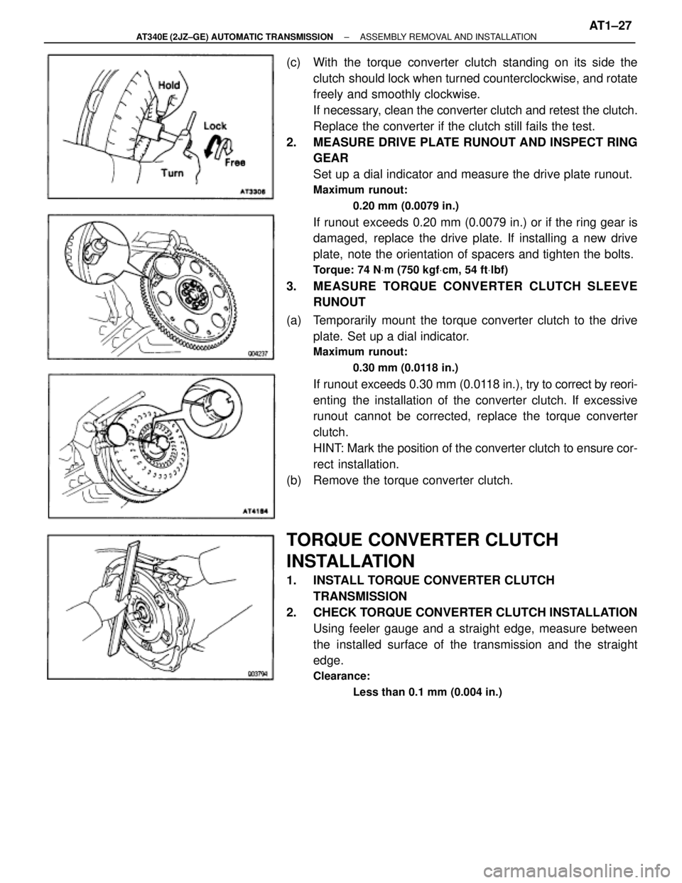
(c) With the torque converter clutch standing on its side the
clutch should lock when turned counterclockwise, and rotate
freely and smoothly clockwise.
If necessary, clean the converter clutch and retest the clutch.
Replace the converter if the clutch still fails the test.
2. MEASURE DRIVE PLATE RUNOUT AND INSPECT RING
GEAR
Set up a dial indicator and measure the drive plate runout.
Maximum runout:
0.20 mm (0.0079 in.)
If runout exceeds 0.20 mm (0.0079 in.) or if the ring gear is
damaged, replace the drive plate. If installing a new drive
plate, note the orientation of spacers and tighten the bolts.
Torque: 74 NVm (750 kgfVcm, 54 ftVlbf)
3. MEASURE TORQUE CONVERTER CLUTCH SLEEVE
RUNOUT
(a) Temporarily mount the torque converter clutch to the drive
plate. Set up a dial indicator.
Maximum runout:
0.30 mm (0.0118 in.)
If runout exceeds 0.30 mm (0.0118 in.), try to correct by reori-
enting the installation of the converter clutch. If excessive
runout cannot be corrected, replace the torque converter
clutch.
HINT: Mark the position of the converter clutch to ensure cor-
rect installation.
(b) Remove the torque converter clutch.
TORQUE CONVERTER CLUTCH
INSTALLATION
1. INSTALL TORQUE CONVERTER CLUTCH
TRANSMISSION
2. CHECK TORQUE CONVERTER CLUTCH INSTALLATION
Using feeler gauge and a straight edge, measure between
the installed surface of the transmission and the straight
edge.
Clearance:
Less than 0.1 mm (0.004 in.)
± AT340E (2JZ±GE) AUTOMATIC TRANSMISSIONASSEMBLY REMOVAL AND INSTALLATIONAT1±27
Page 423 of 2543
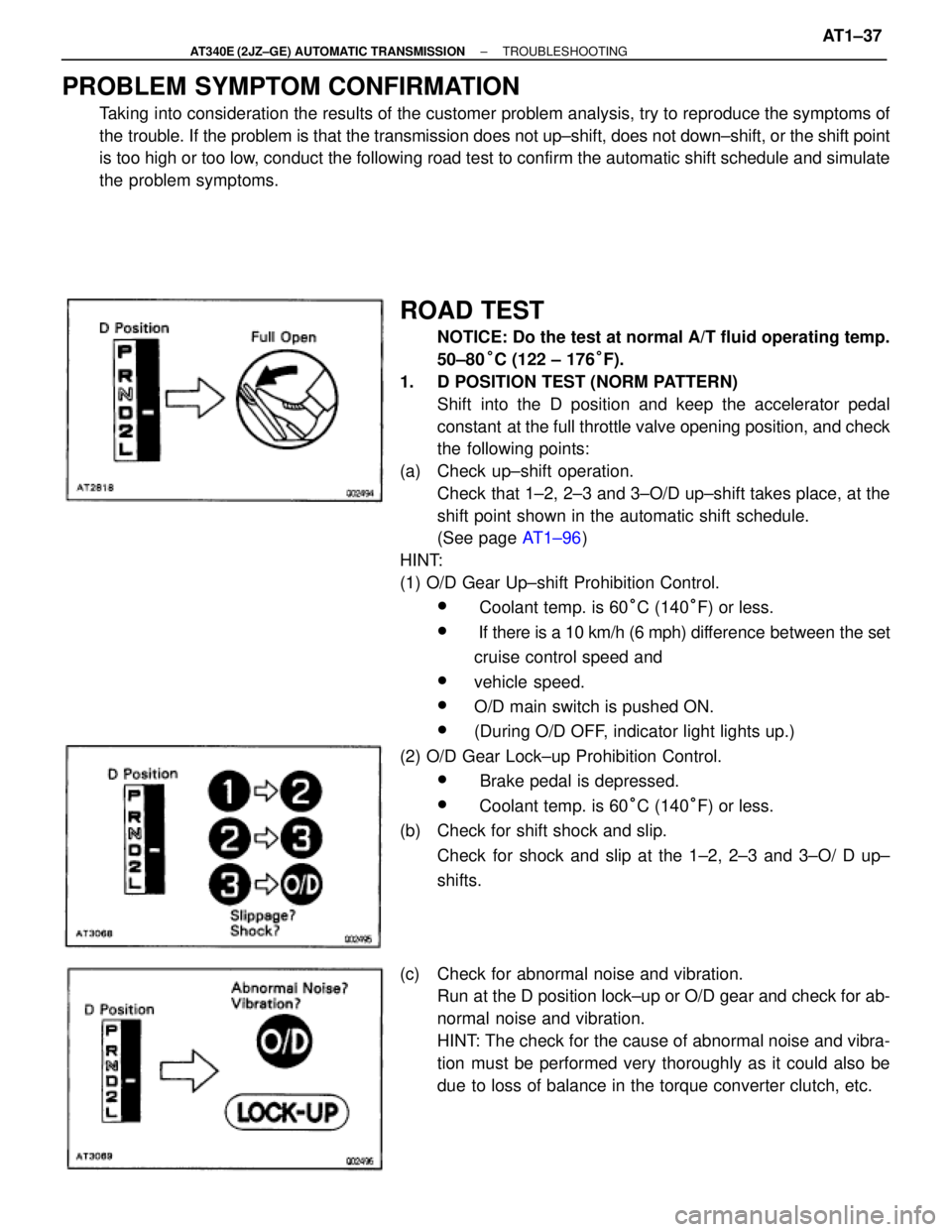
PROBLEM SYMPTOM CONFIRMATION
Taking into consideration the results of the customer problem analysis, try to reproduce the symptoms of
the trouble. If the problem is that the transmission does not up±shift, does not down±shift, or the shift point
is too high or too low, conduct the following road test to confirm the automatic shift schedule and simulate
the problem symptoms.
ROAD TEST
NOTICE: Do the test at normal A/T fluid operating temp.
50±80°C (122 ± 176°F).
1. D POSITION TEST (NORM PATTERN)
Shift into the D position and keep the accelerator pedal
constant at the full throttle valve opening position, and check
the following points:
(a) Check up±shift operation.
Check that 1±2, 2±3 and 3±O/D up±shift takes place, at the
shift point shown in the automatic shift schedule.
(See page AT1±96)
HINT:
(1) O/D Gear Up±shift Prohibition Control.
w Coolant temp. is 60°C (140°F) or less.
w If there is a 10 km/h (6 mph) difference between the set
cruise control speed and
wvehicle speed.
wO/D main switch is pushed ON.
w(During O/D OFF, indicator light lights up.)
(2) O/D Gear Lock±up Prohibition Control.
w Brake pedal is depressed.
w Coolant temp. is 60°C (140°F) or less.
(b) Check for shift shock and slip.
Check for shock and slip at the 1±2, 2±3 and 3±O/ D up±
shifts.
(c) Check for abnormal noise and vibration.
Run at the D position lock±up or O/D gear and check for ab-
normal noise and vibration.
HINT: The check for the cause of abnormal noise and vibra-
tion must be performed very thoroughly as it could also be
due to loss of balance in the torque converter clutch, etc.
± AT340E (2JZ±GE) AUTOMATIC TRANSMISSIONTROUBLESHOOTINGAT1±37