Page 1042 of 2543

wCheck that the arrow mark on the belt tensioner falls
within area A of the scale.
If it is outside area A, replace the drive belt.
HINT:
wWhen a new belt is installed, it should lie within area B.
If not, the drive belt is not correct.
wAfter installing a drive belt, check that it fits properly in
the ribbed grooves.
wCheck by hand to confirm that the belt has not slipped
out of the groove on the bottom of the pulley.
4. REMOVE ENGINE UNDER COVER
5. VISUALLY CHECK GENERATOR WIRING AND LISTEN
FOR ABNORMAL NOISES
(a) Check that the wiring is in good condition.
(b) Check that there is no abnormal noise from the generator
while the engine is running.
6. CHECK CHARGE WARNING LIGHT CIRCUIT
(a) Warm up the engine and then turn it off.
(b) Turn off all accessories.
(c) Turn the ignition switch ºONº. Check that the charge warning
light is lit.
(d) Start the engine. Check that the light goes off. If the light does
not go off as specified, troubleshoot the charge light circuit.
7. INSPECT CHARGING CIRCUIT WITHOUT LOAD
HINT: If a battery/generator tester is available, connect the
tester to the charging circuit as per manufacturer's instruc-
tions.
(a) If a tester is not available, connect a voltmeter and ammeter
to the charging circuit as follows:
wDisconnect the wire from terminal B of the generator,
and connect it to the negative (±) probe of the ammeter.
± CHARGING SYSTEMON±VEHICLE INSPECTIONCH±5
Page 1043 of 2543
 probe of the ammeter to
terminal B of the generator.
wConnect the positive (+) probe of the voltmeter to
terminal B of the generator.
wGround the negative (±) probe of the v")
wConnect the positive (+) probe of the ammeter to
terminal B of the generator.
wConnect the positive (+) probe of the voltmeter to
terminal B of the generator.
wGround the negative (±) probe of the voltmeter.
(b) Check the charging circuit as follows:
With the engine running from idling to 2,000 rpm, check the
reading on the ammeter and voltmeter:
Standard amperage:
10 A or less
Standard voltage:
At 25°C (77°F)
13.6±14.8 V
At 115°C (239°F)
S13.2±14.0 V
If the voltmeter reading is more than standard voltage, re-
place the voltage regulator.
If the voltmeter reading is less than standard voltage, check
the voltage regulator and generator as follows:
wWith terminal F grounded, start the engine and check
the voltmeter reading of terminal B.
wIf the voltmeter reading is more than standard voltage,
replace the voltage regulator.
wIf the voltmeter reading is less than standard voltage,
check the generator.
8. INSPECT CHARGING CIRCUIT WITH LOAD
(a) With the engine running at 2,000 rpm, turn on the high beam
headlights and place the heater blower switch at ºHIº.
(b) Check the reading on the ammeter.
Standard amperage:
30 A or more
If the ammeter reading is less than the standard amperage,
repair the generator.
HINT: If the battery is fully charged, the indication will some-
times be less than standard amperage.
9. REINSTALL ENGINE UNDER COVER CH±6
± CHARGING SYSTEMON±VEHICLE INSPECTION
Page 1057 of 2543
 at 205C (685F)
Sp")
SERVICE SPECIFICATIONS
SERVICE DATA
������� �
������ �
������ �������
Battery���������������� �
��������������� �
��������������� ����������������
Voltage (Maintenance±free battery) at 205C (685F)
Specific gravity (Except maintenance±free battery)
at 205C(685F)��������������� �
�������������� �
�������������� ���������������
12.7±12.9 V
1.27±1.29
������� �
������ �
������ �
������ �
������ �
������ �������
Generator���������������� �
��������������� �
��������������� �
��������������� �
��������������� �
��������������� ����������������
Rated output 2JZ±GE
2JZ±GTE
Rotor coil resistance at 205C (685C)
Slip ring diameter STD
Minimum
Brush exposed length STD
Minimum��������������� �
�������������� �
�������������� �
�������������� �
�������������� �
�������������� ���������������
12 V 90 A
12 V 100 A
2.8±3.0 �
14.2±14.4 mm (0.559±0.567 in.)
12.8 mm (0.504 in.)
10.5 mm (0.413 in.)
1.5 mm (0.059 in.)
������� �
������ �������Voltage
regulator���������������� �
��������������� ����������������Regulating voltage at 255C (775F)
at 1155C (2395F)��������������� �
�������������� ���������������13.6±14.8 V
13.2±14.0 V
TORQUE SPECIFICATIONS
����������������� �����������������Part tightened������� �������NVm������� �������kgfVcm������� �������ftVlbf����������������� �����������������Rectifier end frame X Drive end frame������� �������4.5������� �������46������� �������40 in.Vlbf����������������� �
����������������
�����������������
Generator pulley X Rotor�������
������� �������11 0������� �
������ �������1,125������� �
������ �������81
����������������� �����������������Rectifier holder X Coil lead on rectifier end frame������� �������2.0������� �������20������� �������17 in.Vlbf
����������������� �����������������Rear end cover X Rectifier holder������� �������4.5������� �������46������� �������40 in.Vlbf
����������������� �����������������Plate terminal X Rectifier holder������� �������3.9������� �������40������� �������35 in.Vlbf
����������������� �����������������Terminal insulator X Rectifier holder������� �������6.5������� �������66������� �������58 in.Vlbf
����������������� �����������������Generator X Water pump������� �������37������� �������380������� �������27
����������������� �����������������Generator X Cylinder block������� �������37������� �������380������� �������27
± CHARGING SYSTEMSERVICE SPECIFICATIONSCH±20
Page 1097 of 2543
RADIATOR REMOVAL
Installation is in the reverse order of removal.
1. REMOVE ENGINE UNDER COVER
INSTALLATION HINT: Start the engine, and check for cool-
ant and A/T fluid leaks.
2. REMOVE BATTERY AND BATTERY TRAY
3. DRAIN ENGINE COOLANT
4. 2JZ±GTE:
REMOVE NO.2 AIR TUBE
5. REMOVE NO.2 FAN SHROUD
(a) Remove the 2 clips.
(b) Disconnect the claw of the No.2 fan shroud from the hook of
the No.1 fan shroud, and remove the No.2 fan shroud.
6. REMOVE AIR CLEANER DUCT
7. 2JZ±GTE:
REMOVE NO.5 AIR HOSE
8. REMOVE LH HEADLIGHT BEAM ANGLE GAUGE
Remove the screw and beam angle gauge.
9. DISCONNECT HOSES FROM RADIATOR
Disconnect these hoses from the radiator:
(1) Reservoir inlet hose
(2) Upper radiator hose
(3) Lower radiator hose
(4) A/T:
2 oil cooler hoses
Plug the hose ends.
INSTALLATION HINT: Check the A/T fluid level.
(See item 21 in Maintenance) EG±346
± ENGINECOOLING SYSTEM
Page 1105 of 2543
Cooling Fan
COMPONENTS FOR REMOVAL AND
INSTALLATION
COOLING FAN INSPECTION
INSPECT COOLING FAN
(a) Disconnect the fan connector.
(b) Connect battery and ammeter to the cooling fan connector.
(c) Check that the cooling fan rotates smoothly, and check the
reading on the ammeter.
Standard amperage:
2.5±4.5 A
(d) Reconnect the fan connector. EG±354
± ENGINECOOLING SYSTEM
Page 1108 of 2543
 Apply battery voltage across terminals 3 and 4.
(b) Using an ohmmeter, check that there is continuity between
terminals 1 and 2.
If operation is not as specified, rep")
B. Inspect relay operation
(a) Apply battery voltage across terminals 3 and 4.
(b) Using an ohmmeter, check that there is continuity between
terminals 1 and 2.
If operation is not as specified, replace the relay.
5. REINSTALL RADIATOR FAN RELAY
6. w/ Auto Spoiler:
REINSTALL LH HEADLIGHT
7. w/o Auto Spoiler:
REINSTALL ENGINE UNDER COVER
No.2 Radiator Fan Relay
(ºA.B.S. (TRAC) RELAYº)
RADIATOR FAN RELAY INSPECTION
1. w/ Auto Spoiler:
REMOVE LH HEADLIGHT
2. w/o Auto Spoiler:
REMOVE ENGINE UNDER COVER
3. REMOVE RADIATOR FAN RELAY
4. INSPECT RADIATOR FAN RELAY
A. Inspect relay continuity
(a) Using an ohmmeter, check that there is continuity between
terminals 1 and 6.
(b) Check that there is continuity between terminals 3 and 5.
(c) Check that there is no continuity between terminals 2 and 5.
If continuity is not as specified, replace the relay.
B. Inspect relay operation
(a) Apply battery voltage across terminals 1 and 6.
(b) Usin g an oh mme te r, ch e ck th a t th e re is no co n tin u ity
between terminals 3 and 5.
(c) Check that there is continuity between terminals 2 and 5.
If operation is not as specified, replace the relay.
5. REINSTALL RADIATOR FAN RELAY
6. w/ Auto Spoiler:
REINSTALL LH HEADLIGHT
7. w/o Auto Spoiler:
REINSTALL ENGINE UNDER COVER
± ENGINECOOLING SYSTEMEG±357
Page 1137 of 2543
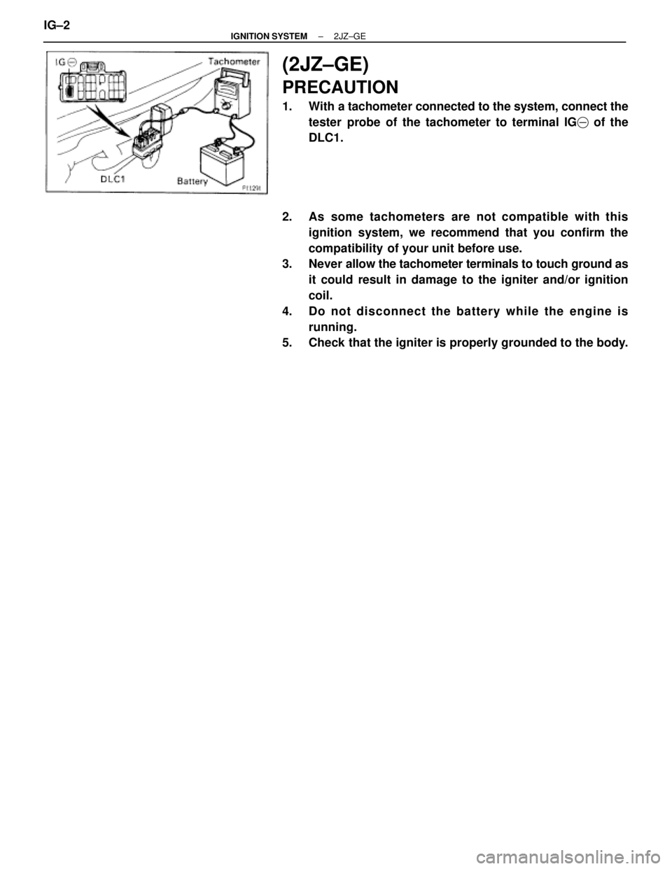
(2JZ±GE)
PRECAUTION
1. With a tachometer connected to the system, connect the
tester probe of the tachometer to terminal IG� of the
DLC1.
2. As some tachometers are not compatible with this
ignition system, we recommend that you confirm the
compatibility of your unit before use.
3. Never allow the tachometer terminals to touch ground as
it could result in damage to the igniter and/or ignition
coil.
4. Do not disconnect the battery while the engine is
running.
5. Check that the igniter is properly grounded to the body. IG±2
± IGNITION SYSTEM2JZ±GE
Page 1139 of 2543
 Disconnect the high±tension cord (from the ignition coil) from
the distributor cap.
(b) Hold the end approx. 12.5 mm (0.50 in.) from t")
ON±VEHICLE INSPECTION
SPARK TEST
CHECK THAT SPARK OCCURS
(a) Disconnect the high±tension cord (from the ignition coil) from
the distributor cap.
(b) Hold the end approx. 12.5 mm (0.50 in.) from the body
ground.
(c) See if spark occurs while engine is being cranked.
HINT: To prevent gasoline from being injected from injectors
during this test, crank the engine for no more than 1±2 se-
conds at time.
If the spark does not occur, do the test as follows:
SPARK TEST
Connect securely.CHECK CONNECTION OF IGNITION COIL,
IGNITER AND DISTRIBUTOR CONNECTOR
CHECK RESISTANCE OF HIGH±TENSION CORD(See page IG±5)
Maximum resistance: 25 k� per cord
CHECK POWER SUPPLY TO IGNITION COIL AND
IGNITER
1. Turn ignition switch to ON.
2. Check that there is battery voltage at
ignition coil positive (+) terminal.
CHECK RESISTANCE OF IGNITION COIL(See page IG±7)Resistance: Cold Hot
Primary 0.21 ± 0.33 �0.27 ± 0.39 �
Secondary 6.4 ± 11.1 k�8.2 ± 13.0 k�
CHECK RESISTANCE OF SIGNAL GENERATOR
(PICKUP COIL)(See page IG±8)Resistance: Cold Hot
G1 and G �125 ± 200 �160 ± 235 �
G2 and G �125 ± 200 �160 ± 235 �
NE and G �155 ± 250 �190 ± 290 �
CHECK AIR GAP OF DISTRIBUTOR(See page IG±8)Air gap: 0.2 ± 0.5 mm (0.008 ± 0.020 in.)
(See page EG±413)
CHECK IGT SIGNAL FROM ECM
TRY ANOTHER IGNITER
Replace the cord(s).
Check wiring between ignition switch to ignition
coil and igniter.
Replace the ignition coil.
Replace the distributor housing assembly.
Replace the distributor housing assembly.
Check wiring between ECM, distributor and
igniter, and then try another ECM.
IG±4± IGNITION SYSTEM2JZ±GE

 Disconnect the fan connector.
(b) Connect battery and ammeter to the cooling fan connector.
(c) Ch")