Page 1849 of 2248
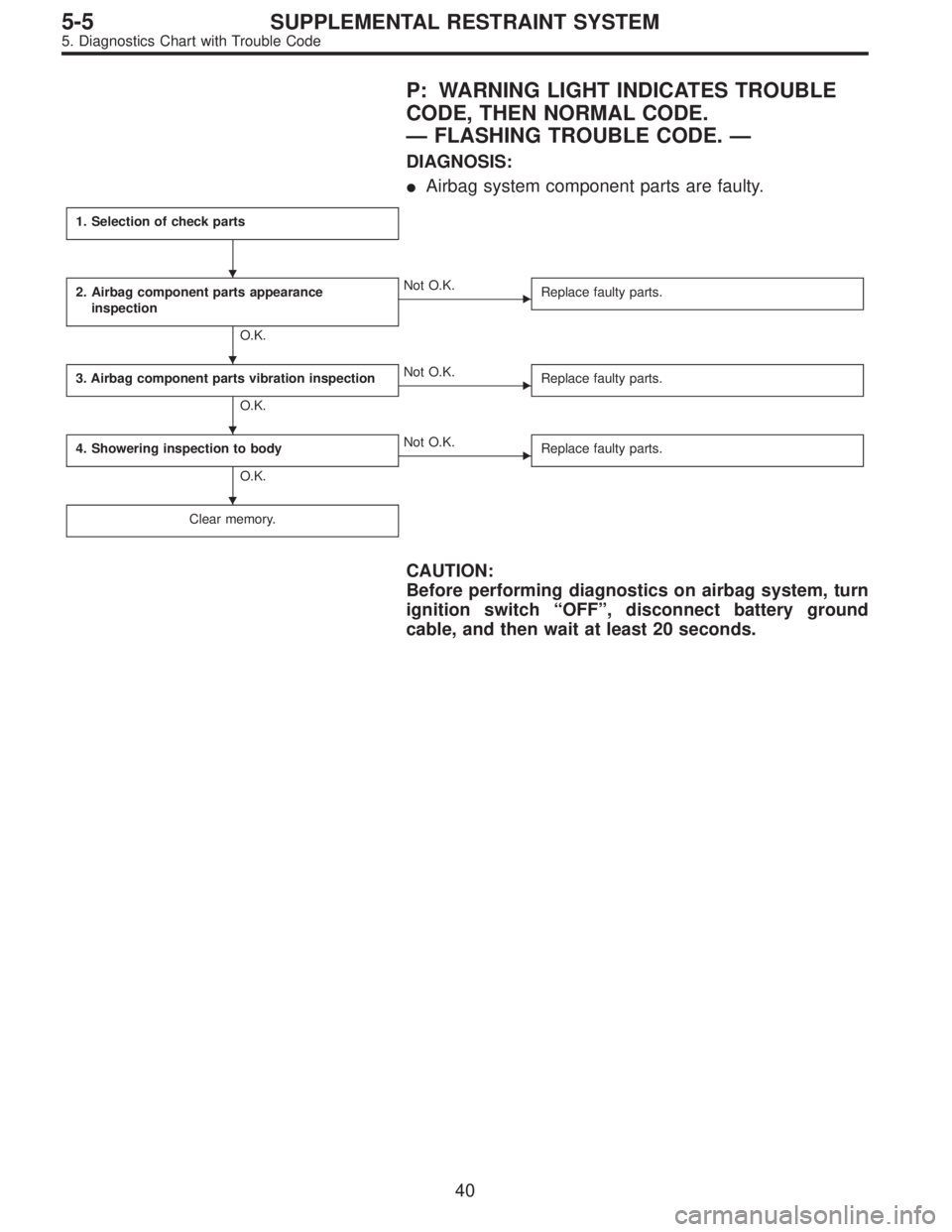
P: WARNING LIGHT INDICATES TROUBLE
CODE, THEN NORMAL CODE.
—FLASHING TROUBLE CODE.—
DIAGNOSIS:
�Airbag system component parts are faulty.
1. Selection of check parts
2. Airbag component parts appearance
inspection
O.K.
�Not O.K.
Replace faulty parts.
3. Airbag component parts vibration inspection
O.K.
�Not O.K.
Replace faulty parts.
4. Showering inspection to body
O.K.
�Not O.K.
Replace faulty parts.
Clear memory.
CAUTION:
Before performing diagnostics on airbag system, turn
ignition switch“OFF”, disconnect battery ground
cable, and then wait at least 20 seconds.
�
�
�
�
40
5-5SUPPLEMENTAL RESTRAINT SYSTEM
5. Diagnostics Chart with Trouble Code
Page 1852 of 2248

Q: WARNING LIGHT INDICATES TROUBLE
CODE, THEN NORMAL CODE.
—FLASHING NORMAL CODE.—
DIAGNOSIS:
�Airbag connector is faulty.
�Fuse No. 16 is blown.
�Airbag main harness is faulty.
�Airbag control module is faulty.
�Body harness is faulty.
1. Airbag connectors appearance and vibration
inspection
O.K.
�Not O.K.
Replace faulty parts.
2. Showering inspection to body
O.K.
�Not O.K.
Replace faulty parts.
3. Fuse No. 16, airbag main harness, airbag
control module, body harness appearance and
vibration inspection
O.K.
�Not O.K.
Replace faulty parts.
4. Showering inspection to body
O.K.
�Not O.K.
Replace faulty parts.
5. Warning light illumination check
O.K.
�Not O.K.
Go to“T4E0”diagnostics procedure.
Clear memory.
CAUTION:
Before performing diagnostics on airbag system, turn
ignition switch“OFF”, disconnect battery ground
cable, and then wait at least 20 seconds.
1. AIRBAG CONNECTORS APPEARANCE AND
VIBRATION INSPECTION
1) Conduct appearance inspection on airbag connectors
(AB2 through AB8).
NOTE:
Check terminals, case and wiring harnesses for damage.
2) Conduct vibration inspection on airbag connectors (AB2
through AB8).
NOTE:
Gently shake each airbag connector.
�
�
�
�
�
43
5-5SUPPLEMENTAL RESTRAINT SYSTEM
5. Diagnostics Chart with Trouble Code
Page 1853 of 2248
 Spray water on vehicle body.
CAUTION:
Do not directly spray water on airbag components.
2) Check passenger compartment for traces of leaking.
NOTE:
If leaks")
G5M0461
2. SHOWERING INSPECTION TO BODY
1) Spray water on vehicle body.
CAUTION:
Do not directly spray water on airbag components.
2) Check passenger compartment for traces of leaking.
NOTE:
If leaks are noted, also check wiring harnesses as water
may leak along them and wet airbag connectors.
3. FUSE No. 16, AIRBAG MAIN HARNESS, AIRBAG
CONTROL MODULE, BODY HARNESS APPEARANCE
AND VIBRATION INSPECTION
1) Conduct appearance inspection on fuse No. 16
5-5 [T5L3].>, airbag main harness ,
airbag control module and body
harness.
NOTE:
Also check connectors, terminals, wiring harness and case
for damage.
2) Conduct vibration inspection on fuse No. 16, airbag
main harness, airbag control module and body harness.
NOTE:
Gently shake each part.
G5M0461
4. SHOWERING INSPECTION TO BODY
1) Spray water on vehicle body.
CAUTION:
Do not directly spray water on each part.
2) Check passenger compartment for traces of leaking.
NOTE:
If leaks are noted, check wiring harnesses as water may
leak along them and get parts wet.
5. WARNING LIGHT ILLUMINATION CHECK
Turn ignition switch“ON”(engine off) and observe airbag
warning light.
Airbag warning light comes“ON”for 8 seconds then goes
out and stays out.
44
5-5SUPPLEMENTAL RESTRAINT SYSTEM
5. Diagnostics Chart with Trouble Code
Page 1860 of 2248

Main power supply 2�Battery voltage is present when main power is tu")
5. Control Module I/O Signal
G6M0015
ContentTerminal
No.Measuring conditions and I/O signals (ignition switch ON and engine idling)
Main power supply 2�Battery voltage is present when main power is turned ON.
�“0”volt is present when main power is turned OFF.
Inhibitor switch (AT) (U.S.A.)
N position switch (AT) (CANADA)4�“0”volt is present when selector lever is set to P or N position (CANADA: N position only).
�Battery voltage is present when selector lever is other than P or N position (CANADA: N
position only).
Air valve 5�“0”volt is present when vehicle is stopped.
�ON-and-OFF (“0”-and-battery voltage) operation is alternately repeated while cruise control
is operating.
GND 6—
Vacuum pump motor 7�“0”volt is present when vehicle is stopped.
�ON-and-OFF (“0”-and-battery voltage) operation is alternately repeated while cruise control
is operating.
Data link connector 8—
RESUME/ACCEL switch 9�Battery voltage is present when switch is turned ON.
�“0”volt is present when switch is turned OFF.
SET/COAST switch 10�Battery voltage is present when switch is turned ON.
�“0”volt is present when switch is turned OFF.
Ignition switch 12�Battery voltage is present when ignition switch is turned ON.
�“0”volt is present when ignition switch is turned OFF.
Release valve 13�“0”volt is present when vehicle is stopped.
�ON-and-OFF (“0”-and-battery voltage) operation is alternately repeated while cruise control
is operating.
Power supply to vacuum pump
motor, air valve, release valve14�“0”volt is present when vehicle is stopped.
�Battery voltage is present while cruise control is operating.
Cruise main switch 15�Battery voltage is present during pressing the main switch, and then approx. 12 V is
present while switch is turned ON.
�“0”volt is present when switch is turned OFF.
Brake switch 16Turn the cruise main switch to ON and leave clutch pedal released (MT).
Then check that;
�“0”volt is present when brake pedal is depressed.
�Battery voltage is present when brake pedal is released.
Additionally only in MT vehicle, keep the cruise main switch to ON and leave brake pedal
released.
Then check that;
�“0”volt is present when clutch pedal is depressed.
�Battery voltage is present when clutch pedal is released.
Data link connector 17—
Data link connector 18—
Vehicle speed sensor 2 19Lift-up the vehicle until all four wheels are raised off ground, and then rotate any wheel manu-
ally.
Approx. 5 and 0 volt pulse signals are alternately input to cruise control module.
Stop light switch 20Turn ignition switch to OFF.
Then check that;
�Battery voltage is present when brake pedal is depressed.
�“0”volt is present when brake pedal is released.
NOTE:
Voltage at terminals 5, 7, 13 and 14 cannot be checked unless vehicle is driving by cruise control operation.
7
6-2BODY ELECTRICAL SYSTEM
5. Control Module I/O Signal
Page 1864 of 2248
7. Diagnostics Chart for Power Line
A: BASIC DIAGNOSTICS PROCEDURE
Drive at cruise speed.
Cruise speed can be set.
(Cruise control is available.)Cruise speed cannot be set.
(Cruise control is not available.)
Check cruise control main switch
light and circuit.
Check cruise control main
switch circuit.
OK
�Not OK
Repair.
Check cruise control main
switch.
OK
�Not OK
Repair.
Faulty cruise control module.
��
�
�
11
6-2BODY ELECTRICAL SYSTEM
7. Diagnostics Chart for Power Line
Page 1865 of 2248
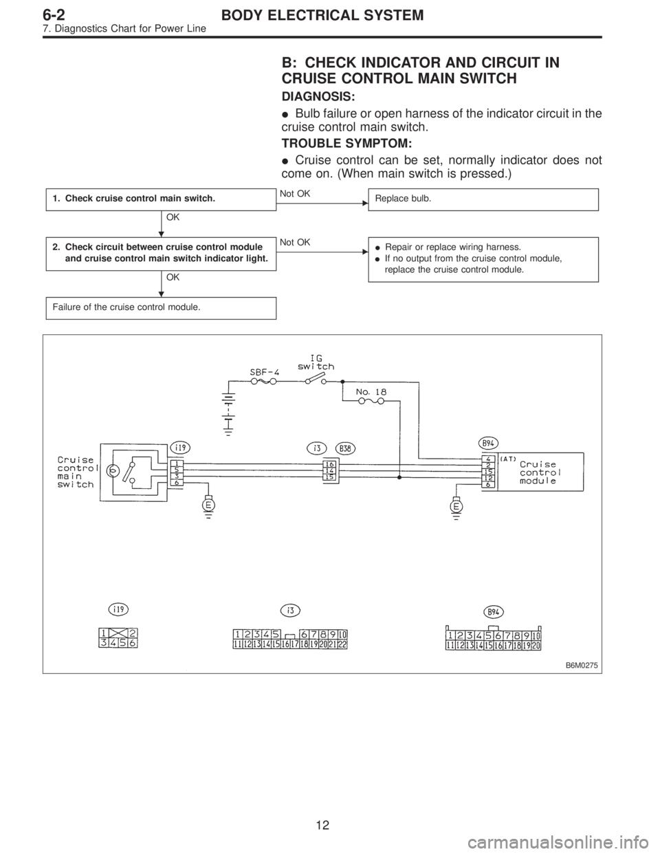
B: CHECK INDICATOR AND CIRCUIT IN
CRUISE CONTROL MAIN SWITCH
DIAGNOSIS:
�Bulb failure or open harness of the indicator circuit in the
cruise control main switch.
TROUBLE SYMPTOM:
�Cruise control can be set, normally indicator does not
come on. (When main switch is pressed.)
1. Check cruise control main switch.
OK
�Not OK
Replace bulb.
2. Check circuit between cruise control module
and cruise control main switch indicator light.
OK
�Not OK
�Repair or replace wiring harness.
�If no output from the cruise control module,
replace the cruise control module.
Failure of the cruise control module.
B6M0275
�
�
12
6-2BODY ELECTRICAL SYSTEM
7. Diagnostics Chart for Power Line
Page 1866 of 2248
B6M0180
1. CHECK CRUISE CONTROL MAIN SWITCH.
1) Remove cruise control main switch.
2) Measure resistance between cruise control main switch
terminals.
Terminals / Specified resistance:
No. 1—No. 6 / Approx. 50Ω
B6M0528A
B6M0531A
2. CHECK CIRCUIT BETWEEN CRUISE CONTROL
MODULE AND CRUISE CONTROL MAIN SWITCH
INDICATOR LIGHT.
1) Turn the ignition switch to ON.
2) Turn cruise control main switch to ON.
3) Measure voltage between cruise control main switch
connector and the body.
Connector & terminal / Specified voltage:
(i19) No. 1—Body / 10 V, or more
4) Turn the ignition switch and cruise control main switch
to OFF.
5) Remove the connector from the cruise control main
switch.
6) Measure resistance of ground circuit between the
cruise control main switch connector and body.
Connector & terminal / Specified resistance:
(i19) No. 6—Body / 10Ω, max.
13
6-2BODY ELECTRICAL SYSTEM
7. Diagnostics Chart for Power Line
Page 1869 of 2248

8. Diagnostics Chart with Trouble Code
A: TROUBLE CODE
Trouble code Item Contents of diagnosis Page
10 OK Normal 18
11 BRAKE/ST/CL or N�Input signals from brake switch“OFF”, stop light
switch“ON”(Brake pedal is in depressed condi-
tion.)
�Input signals from clutch switch“OFF”, or inhibi-
tor switch is in“N”position.
[Clutch pedal is depressed (MT), or select lever
is set to N position (AT).]20
12 NOT SET SP Out of cruise speed range 22
13 LOW SP LIM Low-speed control limiter 22
14 CANCEL SW Input signal from cancel switch 26
15 NO MEMORY No memorized cruise speed—
21 SP SENS NG Faulty vehicle speed sensor 2 22
22 COM SW NGFaulty SET/COAST switch or RESUME/ACCEL
switch26
23 RELAY NG Faulty safety relay included in cruise control module 29
24 CPU RAM NG Faulty CPU RAM included in cruise control module 29
31 MOTOR NG Faulty vacuum motor or motor drive system 30
32 AIR VAL NG Faulty air valve or valve drive system 30
33 REL VAL NG Faulty release valve or valve drive system 30
16
6-2BODY ELECTRICAL SYSTEM
8. Diagnostics Chart with Trouble Code
Cruise speed cannot be set.
(Cruise control is not avai")
 Remove cruise control main switch.
2) Measure resistance between cruise control main switch
terminals.
Terminals / Specified resistance:
No. 1—No. 6 /")