Page 1800 of 2248

B4M0526
Y: TROUBLE CODE 54
1. B.SW HARD
—Break and short circuit at stroke sensor or its
wiring—
DIAGNOSIS:
�Faulty stroke sensor
�Faulty harness/connector
�Faulty stop light switch
�Faulty ABS/TCS control module
TROUBLE SYMPTOM:
�ABS and TCS do not operate.
NOTE:
Operate the function F09 in select monitor TCS mode, and
read the sensor output step.
If system is normal, the output reading is 1 when brake
pedal is not depressed, and it changes from 2 to 3, 4 and
5 in accordance with the brake pedal depressing. If so, skip
check steps 1 through 5.
1. Check resistance of stroke sensor.
OK
�Not OK
Replace stroke sensor.
2. Check stroke sensor operation.
OK
�Not OK
Replace stroke sensor.
3. Check body short of stroke sensor.
OK
�Not OK
Replace stroke sensor.
4. Check harness between stroke sensor and
ABS/TCS control module.
OK
�Not OK
Repair harness/connector.
5. Check body short of stroke sensor harness.
OK
�Not OK
Repair harness.
Replace ABS/TCS control module.
�
�
�
�
�
11 9
4-4bBRAKES
10. Diagnostic Chart with Select Monitor
Page 1801 of 2248
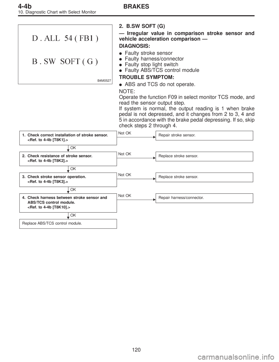
B4M0527
2. B.SW SOFT (G)
—Irregular value in comparison stroke sensor and
vehicle acceleration comparison—
DIAGNOSIS:
�Faulty stroke sensor
�Faulty harness/connector
�Faulty stop light switch
�Faulty ABS/TCS control module
TROUBLE SYMPTOM:
�ABS and TCS do not operate.
NOTE:
Operate the function F09 in select monitor TCS mode, and
read the sensor output step.
If system is normal, the output reading is 1 when brake
pedal is not depressed, and it changes from 2 to 3, 4 and
5 in accordance with the brake pedal depressing. If so, skip
check steps 2 through 4.
1. Check correct installation of stroke sensor.
OK
�Not OK
Repair stroke sensor.
2. Check resistance of stroke sensor.
OK
�Not OK
Replace stroke sensor.
3. Check stroke sensor operation.
OK
�Not OK
Replace stroke sensor.
4. Check harness between stroke sensor and
ABS/TCS control module.
OK
�Not OK
Repair harness/connector.
Replace ABS/TCS control module.
�
�
�
�
120
4-4bBRAKES
10. Diagnostic Chart with Select Monitor
Page 1802 of 2248

—Irregular value in stroke sensor and brake light
switch comparison—
DIAGNOSIS:
�Faulty stroke sensor
�Faulty stop light switch
�Faulty harness/connector
�Faulty ABS/TCS c")
B4M0528
3. B.SW SOFT (B)
—Irregular value in stroke sensor and brake light
switch comparison—
DIAGNOSIS:
�Faulty stroke sensor
�Faulty stop light switch
�Faulty harness/connector
�Faulty ABS/TCS control module
TROUBLE SYMPTOM:
�ABS and TCS do not operate.
NOTE:
Operate the function F09 in select monitor TCS mode, and
read the sensor output step.
If system is normal, the output reading is 1 when brake
pedal is not depressed, and it changes from 2 to 3, 4 and
5 in accordance with the brake pedal depressing. If so, skip
check steps 1 and 2 through 7.
Then, operate the function FA0 and check the stop and
brake switches by B1 LED ON/OFF. If system is normal,
LED comes on when depressing brake pedal, and goes off
when not depressing. If so, skip check steps 3 through 6.
1. Check resistance of stroke sensor.
OK
�Not OK
Replace stroke sensor.
2. Check stroke sensor operation.
OK
�Not OK
Replace stroke sensor.
3. Check contact point of stop light switch.
OK
�Not OK
Replace stroke sensor.
4. Check body short of stop light switch.
OK
�Not OK
Replace stroke sensor.
5. Check power supply of stop light switch.
OK
�Not OK
Repair harness/connector.
6. Check input voltage of ABS/TCS control mod-
ule.
OK
�Not OK
Repair harness/connector.
7. Check harness between stroke sensor and
ABS/TCS control module.
OK
�Not OK
Repair harness/connector.
Replace ABS/TCS control module.
�
�
�
�
�
�
�
121
4-4bBRAKES
10. Diagnostic Chart with Select Monitor
Page 1803 of 2248

—Comparison between stroke sensor and pump
output—
DIAGNOSIS:
�Faulty stroke sensor
�Faulty harness/connector
�Faulty pump unit in hydraulic unit
�Faulty stop light switch")
B4M0529
4. B.SW SOFT (P)
—Comparison between stroke sensor and pump
output—
DIAGNOSIS:
�Faulty stroke sensor
�Faulty harness/connector
�Faulty pump unit in hydraulic unit
�Faulty stop light switch
�Faulty ABS/TCS control module
NOTE:
Operate the function F09 in select monitor TCS mode, and
read the sensor output step.
If system is normal, the output reading is 1 when brake
pedal is not depressed, and it changes from 2 to 3, 4 and
5 in accordance with the brake pedal depressing. If so, skip
check steps 2 through 4.
1. Check correct installation of stroke sensor.
OK
�Not OK
Repair stroke sensor.
2. Check resistance of stroke sensor.
OK
�Not OK
Replace stroke sensor.
3. Check stroke sensor operation.
OK
�Not OK
Replace stroke sensor.
4. Check harness between stroke sensor and
ABS/TCS control module.
OK
�Not OK
Repair harness/connector.
5. Check pump unit operation.
OK
�Not OK
Replace hydraulic unit.
Replace ABS/TCS control module.
�
�
�
�
�
122
4-4bBRAKES
10. Diagnostic Chart with Select Monitor
Page 1804 of 2248
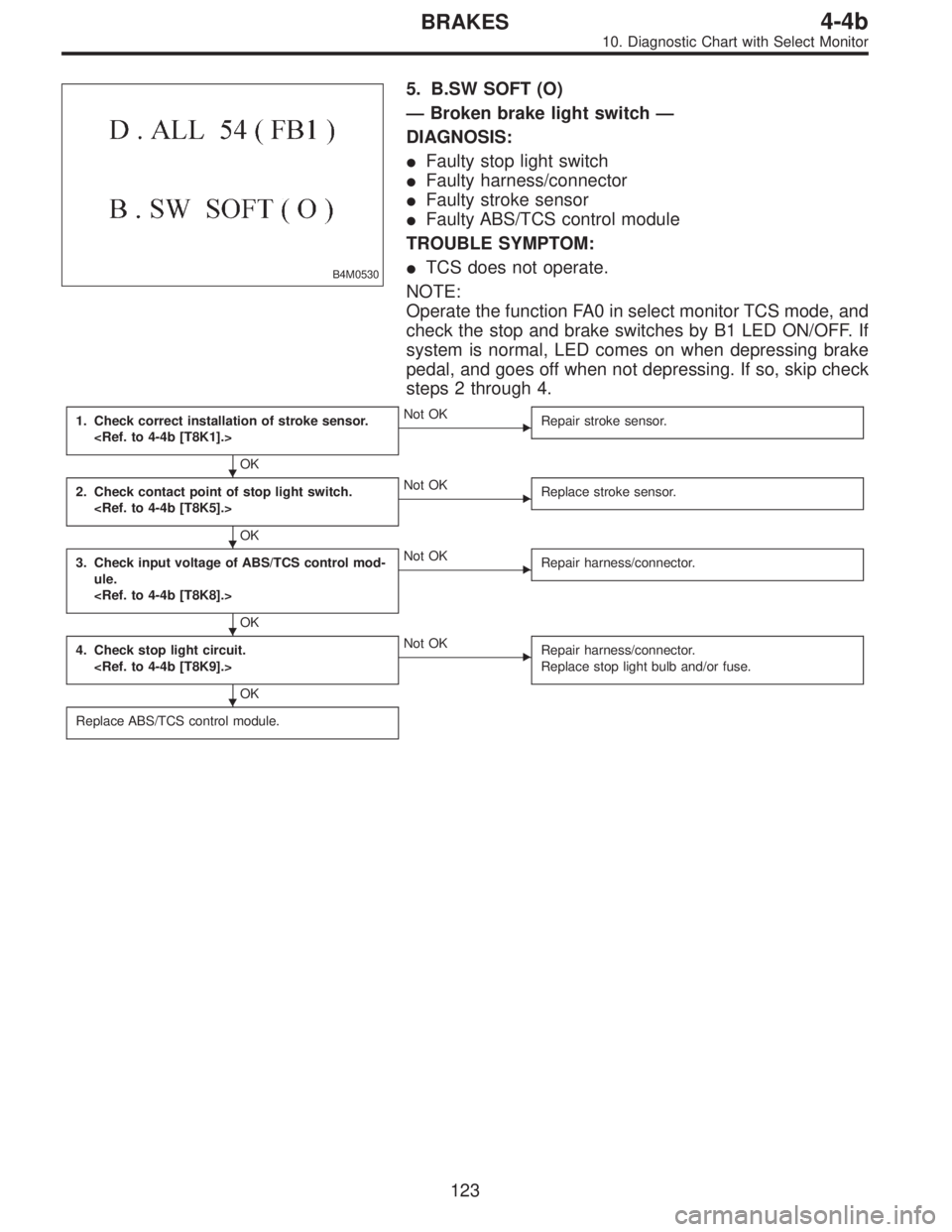
B4M0530
5. B.SW SOFT (O)
—Broken brake light switch—
DIAGNOSIS:
�Faulty stop light switch
�Faulty harness/connector
�Faulty stroke sensor
�Faulty ABS/TCS control module
TROUBLE SYMPTOM:
�TCS does not operate.
NOTE:
Operate the function FA0 in select monitor TCS mode, and
check the stop and brake switches by B1 LED ON/OFF. If
system is normal, LED comes on when depressing brake
pedal, and goes off when not depressing. If so, skip check
steps 2 through 4.
1. Check correct installation of stroke sensor.
OK
�Not OK
Repair stroke sensor.
2. Check contact point of stop light switch.
OK
�Not OK
Replace stroke sensor.
3. Check input voltage of ABS/TCS control mod-
ule.
OK
�Not OK
Repair harness/connector.
4. Check stop light circuit.
OK
�Not OK
Repair harness/connector.
Replace stop light bulb and/or fuse.
Replace ABS/TCS control module.
�
�
�
�
123
4-4bBRAKES
10. Diagnostic Chart with Select Monitor
Page 1806 of 2248

B4M0532
AA: TROUBLE CODE 58
PRESSURE SW
—Faulty pressure switch—
DIAGNOSIS:
�Faulty pressure
�Faulty stop light switch
�Faulty ABS/TCS control module
�Faulty harness/connector
TROUBLE SYMPTOM:
�TCS does not operate.
NOTE:
Check using the select monitor.
Operate the function FA0 in select monitor TCS mode. The
stop and brake switches can be checked by B1 LED
ON/OFF. If system is normal, LED comes on when
depressing brake pedal, and goes off when not depressing.
If so, skip check steps 5 through 8.
1. Check contact point of pressure switch.
OK
�Not OK
Replace hydraulic unit.
2. Check body short of pressure switch.
OK
�Not OK
Replace hydraulic unit.
3. Check harness between pressure switch and
ABS/TCS control module.
OK
�Not OK
Repair harness/connector.
4. Check body short of pressure switch harness.
OK
�Not OK
Repair harness.
5. Check contact point of stop light switch.
OK
�Not OK
Replace stroke sensor.
6. Check body short of stop light switch.
OK
�Not OK
Replace stroke sensor.
7. Check power supply of stop light switch.
OK
�Not OK
Repair harness.
8. Check input voltage of ABS/TCS control mod-
ule.
OK
�Not OK
Repair harness/connector.
Replace ABS/TCS control module.
�
�
�
�
�
�
�
�
125
4-4bBRAKES
10. Diagnostic Chart with Select Monitor
Page 1809 of 2248
 and,
when it operates, acceleration can become slow*. T")
12. Phenomena Peculiar to the System
1. WHEN TRAVELING WITH EXTREMELY UNDER
INFLATED TIRES
The TCS is apt to operate (particularly when turning) and,
when it operates, acceleration can become slow*. This
state is not abnormal. Immediately restore the tires to nor-
mal by traveling after releasing the TCS with the TCS OFF
switch.
* Poor acceleration is sometimes caused by the engine
itself. Check whether or not the TCS operating indicator
light (green) comes on to determine that the failure is
caused by the TCS control.
2. WHEN THE T TIRES ARE FITTED
The TCS is apt to operate (particularly when turning) and,
when it operates, acceleration can become slow. This state
is not abnormal. Immediately restore the tires to normal by
traveling after releasing the TCS with the TCS OFF switch.
3. WHEN OPERATING THE TCS CONTINUOUSLY ON
A SLOPE IMPOSSIBLE TO CLIMB OR IN STACK
S TAT E
When operating the TCS for a long time, it can be auto-
matically turned off (the OFF indicator light will come on),
stopping braking. This state is not abnormal. It automati-
cally resets by stopping and leaving the vehicle.
4. WHEN HEAVY LOAD IS PLACED ON THE BRAKES
If service brakes are used too often when descending a
long slope, heavy load can be placed on the brakes. To
prevent this problem, the TCS is automatically turned off
(the OFF indicator light will come on). This state is not
abnormal. Stop the vehicle and leave it in the same way as
step 3, it automatically resets.
5. KICKBACK TO THE BRAKE PEDAL WHEN THE
ABS IS OPERATING
Compared with ABS of the AWD model system, pedal kick-
back with large amplitude of vibration and long cycle can
be felt. This is caused by the difference in system configu-
ration and, therefore, not abnormal. If you receive an
inquiry from your clients, fully explain this point.
128
4-4bBRAKES
12. Phenomena Peculiar to the System
Page 1818 of 2248

B5M0115B
B: ON-BOARD DIAGNOSTIC
When the airbag system is in functioning condition, the
airbag warning light will remain on for 8 seconds and go out
when the ignition switch is set to ON.
If there is any malfunction, the airbag warning light will
either stay on or off continuously. In such cases, perform
on-board diagnostic in accordance with the specified pro-
cedure to determine trouble codes.
1) Turn ignition switch ON (with engine OFF).
2) Connect DIAG. terminal�
1to No. 1 terminal of diagno-
sis connector�
2located below lower cover.
3) Check in accordance with the trouble code indicated by
the AIRBAG warning light, and record the trouble codes.
4) Turn the ignition switch “OFF” and remove the DIAG.
terminal from No.1 terminal of diagnosis connector.
B5M0116B
C: CLEAR MEMORY
After eliminating problem as per trouble code, clear
memory as follows:
Make sure ignition switch is ON (and engine off). Connect
one DIAG. terminal�
1on diagnosis connector�2terminal
No. 1.
While warning light is flashing, connect the other DIAG.
terminal�
3on terminal No. 2 for at least three seconds.
After memory is cleared, normal warning light flashing rate
resumes. (Warning light flashes every 0.6 seconds ON-
OFF operation.) Memory cannot be cleared if any problem
exists.
After clear memory and then DIAG. terminals�
1and�3,
extract from diagnosis connector�
2.
9
5-5SUPPLEMENTAL RESTRAINT SYSTEM
4. Diagnostics Chart for On-board Diagnostic System