Page 1191 of 2248

From the previous step
Starter motor runs.
OK
� Not OK
Check starter interrupt relay.
Check wiring harness.
Check security control module.
Check driver’s door unlock switch.
Lock the driver’s door without using a ignition key. (Set the inside
lock knob to LOCK and then close the door while lifting the outer
handle).
Within 30 seconds after the above step, open rear LH door.
Indicator light flashes with short intervals (1 Hz).
OK
� Not OK
Check rear LH door switch.
Check rear LH door switch harness.
Check security control module.
Close and lock door.
Indicator light illuminates continuously.
OK
Perform the above steps also on the rear RH door and front RH
door.
OK
� Not OK
Check rear and front RH door switches.
Check wiring harnesses.
Check security control module.
Pull engine hood opener lever and open engine hood.
Indicator light flashes at short intervals (1 Hz).
OK
� Not OK
Check hood switch.
Check hood switch harness.
Check security control module.
Close engine hood.
Indicator light illuminates continuously.
SEDAN
� WAGON
Unlock rear gate by operating driver’s door inside lock knob and
open rear gate.
Pull trunk opener lever and open trunk lid.Indicator light flashes at short intervals (1 Hz).
OK Not OK
Indicator light flashes at short intervals (1 Hz).
OK Not OKCheck rear gate switch.
Check rear gate switch harness.
Check security control module.
Check trunk switch.
Check trunk switch harness.
Check security control module.Close rear gate and lock by locking driver’s door using a
ignition key.
Close trunk lid.Indicator light illuminates continuously.
Indicator light illuminates continuously.Wait for 30 seconds.
Wait for 30 seconds.Indicator light flashes at long intervals (0.2 sec. ON and 2.4
sec. OFF).
Continues to next step. Continues to next step.
�
�
�
�
�
�
�
�
�
�
�
��
��
��
��
��
��
��
87
6-2DIAGNOSTICS
6. Security System
Page 1197 of 2248
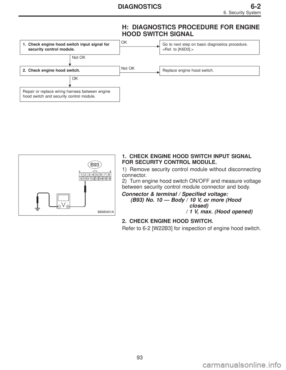
H: DIAGNOSTICS PROCEDURE FOR ENGINE
HOOD SWITCH SIGNAL
1. Check engine hood switch input signal for
security control module.
Not OK
�OK
Go to next step on basic diagnostics procedure.
2. Check engine hood switch.
OK
�Not OK
Replace engine hood switch.
Repair or replace wiring harness between engine
hood switch and security control module.
B6M0451A
1. CHECK ENGINE HOOD SWITCH INPUT SIGNAL
FOR SECURITY CONTROL MODULE.
1) Remove security control module without disconnecting
connector.
2) Turn engine hood switch ON/OFF and measure voltage
between security control module connector and body.
Connector & terminal / Specified voltage:
(B93) No. 10—Body / 10 V, or more (Hood
closed)
/ 1 V, max. (Hood opened)
2. CHECK ENGINE HOOD SWITCH.
Refer to 6-2 [W22B3] for inspection of engine hood switch.
�
�
93
6-2DIAGNOSTICS
6. Security System
Page 1208 of 2248
 system detects and
indicates a fault in various inputs and outputs of the com-
plex electronic control. CHECK ENGINE malfunction indi-")
1. General
1. GENERAL DESCRIPTION
�The on-board diagnostics (OBD) system detects and
indicates a fault in various inputs and outputs of the com-
plex electronic control. CHECK ENGINE malfunction indi-
cator lamp (MIL) in the combination meter indicates occur-
rence of a fault or trouble.
�Further, against such a failure or sensors as may disable
the drive, the fail-safe function is provided to ensure the
minimal driveability.
�The OBD system incorporated with the vehicles within
this engine family complies with Section 1968.1, California
Code of Regulations (OBD-II regulation). The OBD system
monitors the components and the system malfunction
listed in Engine Section which affects on emissions.
�When the system decides that a malfunction occurs, MIL
illuminates. At the same time of the MIL illumination or
blinking, a diagnostic trouble code (DTC) and a freeze
frame engine conditions are stored into on-board com-
puter.
�The OBD system stores freeze frame engine condition
data (engine load, engine coolant temperature, fuel trim,
engine speed and vehicle speed, etc.) into on-board com-
puter when it detects a malfunction first.
�If the OBD system detects the various malfunctions
including the fault of fuel trim or misfire, the OBD system
first stores freeze frame engine conditions about the fuel
trim or misfire.
�When the malfunction does not occur again for three
trips, MIL is turned off, but DTC remains at on-board com-
puter.
�The OBD-II system is capable of communication with a
general scan tool (OBD-II general scan tool) formed by ISO
9141 CARB.
�The OBD-II diagnostics procedure is different from the
usual diagnostics procedure. When troubleshooting OBD-II
vehicles, connect Subaru select monitor or the OBD-II gen-
eral scan tool to the vehicle.
A: ENGINE
1. ENGINE AND EMISSION CONTROL SYSTEM
�The Multipoint Fuel Injection (MFI) system is a system
that supplies the optimum air-fuel mixture to the engine for
all the various operating conditions through the use of the
latest electronic technology.
With this system fuel, which is pressurized at a constant
pressure, is injected into the intake air passage of the cyl-
inder head. The injection quantity of fuel is controlled by an
intermittent injection system where the electro-magnetic
injection valve (fuel injector) opens only for a short period
of time, depending on the quantity of air required for one
cycle of operation. In actual operation, the injection quan-
2
2-7ON-BOARD DIAGNOSTICS II SYSTEM
1. General
Page 1209 of 2248
tity is determined by the duration of an electric pulse
applied to the fuel injector and this permits simple, yet
highly precise metering of the fuel.
�Further, all the operating conditions of the engine are
converted into electric signals, and this results in additional
features of the system, such as large improved
adaptability, easier addition of compensating element, etc.
The MFI system also has the following features:
1) Reduced emission of harmful exhaust gases.
2) Reduced in fuel consumption.
3) Increased engine output.
4) Superior acceleration and deceleration.
5) Superior startability and warm-up performance in cold
weather since compensation is made for coolant and
intake air temperature.
3
2-7ON-BOARD DIAGNOSTICS II SYSTEM
1. General
Page 1211 of 2248

�
2Ignition coil
�
3Ignitor
�
4Crankshaft position sensor
�
5Camshaft position sensor
�
6Throttle position sensor
�
7Fuel injectors
�
8Pressure regulator
�
9Engine coolan")
�1Engine control module (ECM)
�
2Ignition coil
�
3Ignitor
�
4Crankshaft position sensor
�
5Camshaft position sensor
�
6Throttle position sensor
�
7Fuel injectors
�
8Pressure regulator
�
9Engine coolant temperature sensor
�
10Mass air flow sensor
�
11Idle air control solenoid valve
�
12Purge control solenoid valve
�
13Fuel pump
�
14PCV valve
�
15Air cleaner
�
16Canister
�
17Main relay
�
18Fuel pump relay
�
19Fuel filter
�
20Front catalytic converter
�
21Rear catalytic converter
�
22EGR valve�
23EGR control solenoid valve
�
24Radiator fan
�
25Radiator fan relay
�
26Pressure sources switching solenoid valve (AT vehicles only)
�
27Knock sensor
�
28Back-pressure transducer (AT vehicles only)
�
29Front oxygen sensor
�
30Rear oxygen sensor
�
31Pressure sensor (AT vehicles only)
�
32A/C compressor
�
33Inhibitor switch
�
34CHECK ENGINE malfunction indicator lamp (MIL)
�
35Tachometer
�
36A/C relay
�
37A/C control module
�
38Ignition switch
�
39Transmission control module (TCM) (AT vehicles only)
�
40ABS/TCS control module (TCS equipped models)
�
41Vehicle speed sensor
�
42Data link connector (Subaru select monitor)
�
43Data link connector (OBD-II general scan tool)
�
44Two way valve
5
2-7ON-BOARD DIAGNOSTICS II SYSTEM
1. General
Page 1214 of 2248
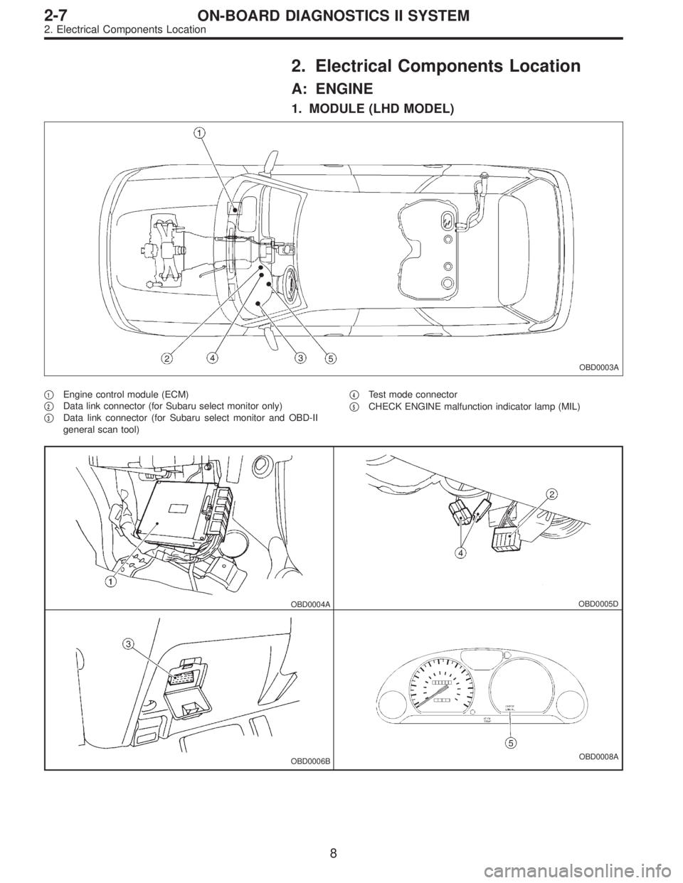
2. Electrical Components Location
A: ENGINE
1. MODULE (LHD MODEL)
OBD0003A
�1Engine control module (ECM)
�
2Data link connector (for Subaru select monitor only)
�
3Data link connector (for Subaru select monitor and OBD-II
general scan tool)�
4Test mode connector
�
5CHECK ENGINE malfunction indicator lamp (MIL)
OBD0004AOBD0005D
OBD0006BOBD0008A
8
2-7ON-BOARD DIAGNOSTICS II SYSTEM
2. Electrical Components Location
Page 1215 of 2248
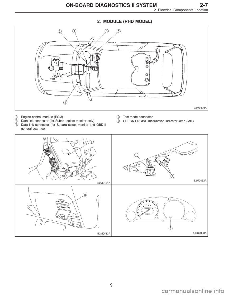
2. MODULE (RHD MODEL)
B2M0430A
�1Engine control module (ECM)
�
2Data link connector (for Subaru select monitor only)
�
3Data link connector (for Subaru select monitor and OBD-II
general scan tool)�
4Test mode connector
�
5CHECK ENGINE malfunction indicator lamp (MIL)
B2M0431AB2M0432A
B2M0433AOBD0008A
9
2-7ON-BOARD DIAGNOSTICS II SYSTEM
2. Electrical Components Location
Page 1216 of 2248
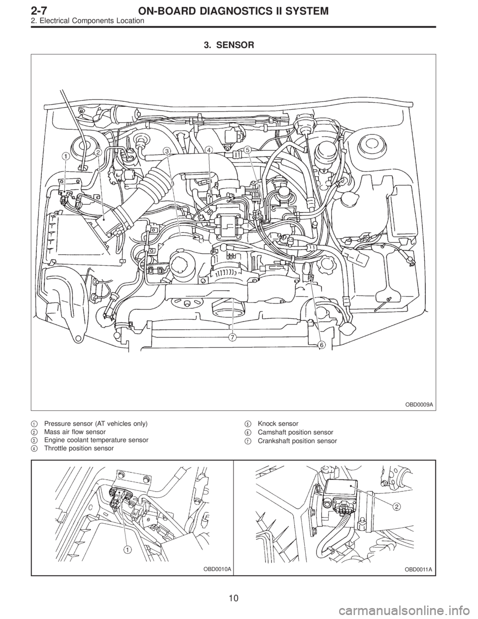
3. SENSOR
OBD0009A
�1Pressure sensor (AT vehicles only)
�
2Mass air flow sensor
�
3Engine coolant temperature sensor
�
4Throttle position sensor�
5Knock sensor
�
6Camshaft position sensor
�
7Crankshaft position sensor
OBD0010AOBD0011A
10
2-7ON-BOARD DIAGNOSTICS II SYSTEM
2. Electrical Components Location