Page 883 of 2248
 The A/C system to be tested must have an adequate
refrigerant charge to begin with.
2) The are")
8. Leak Testing
The following points should be kept in mind when conduct-
ing a refrigerant leak test.
1) The A/C system to be tested must have an adequate
refrigerant charge to begin with.
2) The area where the leak test is conducted must be free
of wind and drafts, with still air being the ideal condition.
3) The atmosphere where the leak test is conducted must
be free of refrigerant contamination.
4) Operate the A/C system for approx. 10 minutes, then
turn the engine off an begin the leak test.
5) Refrigerant gas is heavier than air, therefore always
hold the probe below the connection being tested.
6) When checking for a leak along a length of hose or
tube, the leak detector probe must be moved slowly,
approx. 25 mm (1 in) per second making sure probe does
not come in contact with the component being tested.
7) When checking for a leak at a certain point, the leak
detector probe must be held at that point for at least 5
seconds.
G4M0609
1. CHECK THE SYSTEM PRESSURE
With gauges connected to the A/C system, operate the A/C
and confirm that the high side pressure is above 690 kPa
(7.03 kg/cm
2, 100 psi). If not, evacuate and charge the
system before leak checking (refer to evacuation and
charging sections).
2. CLEAN CONNECTIONS BEFORE TESTING
Before testing, use a clean shop towel to wipe off refriger-
ant oil, dirt, or foreign material from all of the connections
and components to be tested.
NOTE:
Since refrigerant oil absorbs refrigerant, excess oil on or
near a connection may falsely signal a leak.
B4M0089
3. CALIBRATE LEAK DETECTOR
Refer to the manufacturer’s instructions for the particular
type of detector used and calibrate the instrument.
CAUTION:
Always make sure that the probe tip filter is clean and
free of contamination.
23
4-7SERVICE PROCEDURE
8. Leak Testing
Page 884 of 2248
 Begin at the connection of the high-pressure tube to the")
G4M0612
4. LEAK TEST — HIGH-PRESSURE SIDE
Operate the A/C system for approx. 10 minutes, then turn
the engine off and begin the leak test.
1) Begin at the connection of the high-pressure tube to the
evaporator, and work your way along the high- pressure
side of the system to the compressor. There are three
places to check on each tube connection.
2) Check the area.
(1) Check the area where the fitting joins the tube.
G4M0613
(2) Check the area where the two parts of the fitting
join each other.
G4M0614
(3) Check the area where the nut joins the tube.
3) Check the area of the sight glass and pressure switch
(dual switch), and also check the seams of the receiver
drier.
4) Check the connections of the tubes to the condenser,
and also check any welded joints on the condenser.
CAUTION:
An oily area on the fins of the condenser may indicate
a leak.
5) Check the area where the hoses attach to the compres-
sor.
6) Check around the machined portions of the compressor
(where the compressor sections join each other).
7) If equipped, check the thermal limiter on the compres-
sor housing.
8) Check the compressor shaft seal by probing near the
center of the compressor clutch pulley.
NOTE:
Some shaft seals have a very slight amount of normal
leakage [approximately 28 g (1.0 oz) per year].
24
4-7SERVICE PROCEDURE
8. Leak Testing
Page 887 of 2248
 the system must be stabilized for cor-
rect oil replenishment.
Follow these p")
9. Lubrication
1. SYSTEM OIL STABILIZATION
Prior to opening the refrigerant system for repairs (except
compressor seizure) the system must be stabilized for cor-
rect oil replenishment.
Follow these procedures:
1) Engine speed set to 1,500 rpm
2) A/C“ON”
3) Air source to recirculate
4) Blower in 4th or high speed position
�Make sure the air entering the evaporator is above
26.7°C (80°F).
�The discharge (high) side pressure must be above
588 kPa (6 kg/cm
2, 85 psi).
5) Operate the A/C for 10 minutes.
2. SYSTEM DISCHARGE
Slowly, discharge the system starting with the high- pres-
sure side until the pressure drops below 345 kPa (3.52
kg/cm
2, 50 psi), then open the low-pressure side.
3. OIL REPLACEMENT (LHD MODEL)
After stabilization and discharge, replace the component,
adding the appropriate amount of oil (ZXL100PG) to the
new component before installation.
Evaporator 114 m�(3.9 US fl oz, 4.0 Imp fl oz)
Receiver drier 5 m�(0.2 US fl oz, 0.2 Imp fl oz)
Condenser 2 m�(0.07 US fl oz, 0.07 Imp fl oz)
Hose 1 m�(0.03 US fl oz, 0.04 Imp fl oz)
If the compressor is replaced (after stabilization):
1) Drain and measure the oil from the original compressor.
2) Drain the oil from the replacement compressor and refill
with the same amount that was drained from the original
[20 m�(0.7 US fl oz, 0.7 Imp fl oz) minimum]. Always use
ZXL100PG for the replacement oil.
27
4-7SERVICE PROCEDURE
9. Lubrication
Page 889 of 2248
 Vehicle in shade
2) No wind
3) All vehicle doors clos")
10. Performance Test
1. VEHICLE SET UP
In order to obtain meaningful test results, the vehicle must
be set up to meet the following conditions:
1) Vehicle in shade
2) No wind
3) All vehicle doors closed
4) Front windows opened
5) Hood opened
6) Engine speed set at 1,500 rpm.
7) A/C ON
8) Temperature control lever—Maximum cold
9) Air source—Recirculation
10) Blower speed—4th position (High)
11) Operate A/C for 10 minutes (Minimum) before taking
measurement.
2. MEASUREMENTS
After 10 minutes (Minimum) of A/C operation and using
accurate test equipment, take the following measurements
(in order):
1) Evaporator intake air temperature at recirculation door.
2) Evaporator discharge air temperature at center grill.
3) Condenser (Ambient) intake air temperature measured
0.9 m (3 ft) in front and in line with the center of the con-
denser.
4) Suction (Low) side pressure
5) Discharge (High) side pressure
NOTE:
If only one thermometer is available; 1) take the ambient
measurement first; then 2) the intake air; and 3) dis-
charge air temperature.
29
4-7SERVICE PROCEDURE
10. Performance Test
Page 894 of 2248
 Connect compressor harness.
3) Connect alternator harness.
4) Install compressor V-belt (Rear).
After adjusting belt tension, tighten tension pulley lock nut
securely.
G4M0632
5) Install alternator")
2) Connect compressor harness.
3) Connect alternator harness.
4) Install compressor V-belt (Rear).
After adjusting belt tension, tighten tension pulley lock nut
securely.
G4M0632
5) Install alternator V-belt.
After adjusting V-belt tension, tighten alternator bracket
lock bolt securely.
6) Check drive belt tension and adjust it if necessary by
changing alternator position and/or idler pulley position.
Pulley arrangement Tension mm (in)/98N (10 kg, 22 lb)
G4M0939
AB
*New belt:
7.0—9.0
(0.276—0.354)
Existing belt:
9.0—11.0
(0.354—0.433)*New belt:
7.5—8.5
(0.295—0.335)
Existing belt:
9.0—10.0
(0.354—0.394)
* When replacing belts with new ones, adjust tensions to
specification and then readjust to the same specification
after running engine for 5 minutes.
Figures in table refer to the number of grooves in pulleys.
C/P : Crankshaft pulley
ALT : Alternator pulley
P/S : Power steering oil pump pulley
A/C : Air conditioner compressor pulley
I/P : Idler pulley
34
4-7SERVICE PROCEDURE
11. Compressor
Page 908 of 2248

Condition Probable cause Corrective action
FAULTY CONDENSER
G4M0680
No cooling action;
Engine may overheat.
Suction line is very hot.Condenser is often
found not functioning
well.�Check condenser
cooling fan.
�Check condenser for
dirt accumulation.
�Check engine cooling
system for overheat.
�Check for refrigerant
overcharge.
If pressure remains
high in spite of all
above actions taken,
remove and inspect
the condenser for pos-
sible oil clogging.
HIGH-PRESSURE LINE BLOCKED
G4M0681
Insufficient cooling;
Frosted high-pressure
liquid line.Drier is clogged, or
restriction in high-pres-
sure line.1. Discharge system.
2. Remove receiver
drier or strainer and
replace it.
3. Evacuate and charge
system.
FAULTY COMPRESSOR
G4M0682
Insufficient cooling Internal problem is in
compressor, or dam-
aged gasket and valve.1. Discharge system.
2. Remove and check
compressor.
3. Repair or replace
compressor.
4. Check oil level.
5. Replace receiver
drier.
6. Evacuate and charge
system.
46
4-7DIAGNOSTICS
2. Performance Test Diagnosis
Page 912 of 2248
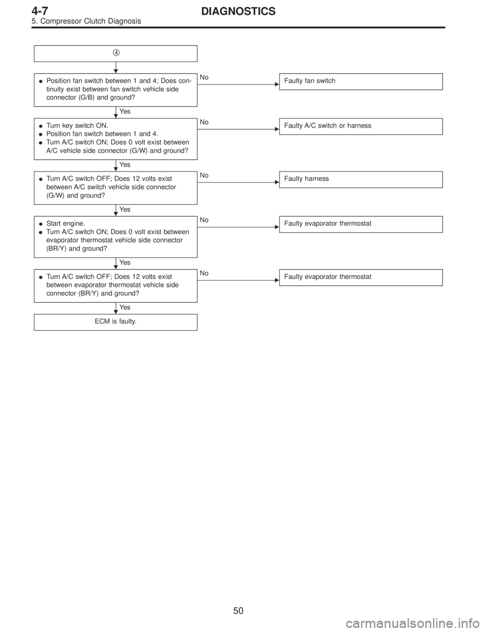
�A
�Position fan switch between 1 and 4; Does con-
tinuity exist between fan switch vehicle side
connector (G/B) and ground?
Ye s
�No
Faulty fan switch
�Turn key switch ON.
�Position fan switch between 1 and 4.
�Turn A/C switch ON; Does 0 volt exist between
A/C vehicle side connector (G/W) and ground?
Ye s
�No
Faulty A/C switch or harness
�Turn A/C switch OFF; Does 12 volts exist
between A/C switch vehicle side connector
(G/W) and ground?
Ye s
�No
Faulty harness
�Start engine.
�Turn A/C switch ON; Does 0 volt exist between
evaporator thermostat vehicle side connector
(BR/Y) and ground?
Ye s
�No
Faulty evaporator thermostat
�Turn A/C switch OFF; Does 12 volts exist
between evaporator thermostat vehicle side
connector (BR/Y) and ground?
Ye s
�No
Faulty evaporator thermostat
ECM is faulty.
�
�
�
�
�
�
50
4-7DIAGNOSTICS
5. Compressor Clutch Diagnosis
Page 916 of 2248
 Operate the engine at approximately 1,500 rpm.
2) Open the door windows.
3) Set the fan switch to the 4th (High) position.
4) Set the mode selector")
9. Sight Glass Inspection
1. INSPECTION CONDITION
1) Operate the engine at approximately 1,500 rpm.
2) Open the door windows.
3) Set the fan switch to the 4th (High) position.
4) Set the mode selector switch to“A/C”position.
5) Set the temperature control switch to Full cold position.
6) Ensure that compressor discharge pressure is at least
588 kPa (6 kg/cm
2, 85 psi).
NOTE:
When discharge pressure does not reach 588 kPa (6
kg/cm
2, 85 psi) in areas where outside air temperature is
low, proceed as follows:
a. Set the TEMP. SWITCH to the Full hot position.
b. Set the temperature control switch to“MAX. A/C”posi-
tion.
c. Close the door windows completely.
d. Increase the compartment temperature so that dis-
charge pressure reaches at least 588 kPa (6 kg/cm
2,85
psi).
2. REFRIGERANT CHARGE AMOUNT CHECKING
Check the refrigerant charge amount using the following
table as a guide.
Item to check Adequate Insufficient Almost in refrigerant Too much refrigerant
State in sight glassCLEAR
Air bubbles sometimes
appear when engine
speed is increased or
decreased.
G4M0669
FOAMY or BUBBLY
Air bubbles always
appear.
G4M0670
FROSTY
Frost-like appears.
G4M0671
NO FOAM
No air bubbles appear.
G4M0672
Temperature of high
and low pressure linesHigh-pressure side is
hot while low-pressure
side is cold. (A big
temperature difference
between high and low
pressure side)High-pressure side is
warm and low-pressure
side is slightly cold.
(Not so big temperature
difference between high
and low pressure side)There is almost no
temperature difference
between high and low
pressure side.High-pressure side is
hot and low-pressure
side is slightly warm.
(Slight temperature
difference between high
and low pressure side)
Pressure of systemBoth pressures on high
and low pressure sides
are normal.Both pressures on high
and low pressure sides
are slightly low.High-pressure side is
abnormally low.Both pressures on high
and low pressure sides
are abnormally high.
54
4-7DIAGNOSTICS
9. Sight Glass Inspection