Page 717 of 2248
1. Brakes
A: SPECIFICATIONS
1. MODELS WITH ABS AND ABS/TCS
Model Sedan Wagon
Engine (cc) 2200 2200
Driving system FWD AWD FWD AWD
L+ L+ LS, LSi L+ L, L+ LS, LSi
Front
brakeType Disc (Floating type, ventilated)
Effective disc diameter
mm (in)210 (8.27)
Disc thickness x Outer
diameter
mm (in)24 x 260 (0.94 x 10.24)
Effective cylinder
diameter
mm (in)57.2 (2.252)
Pad dimensions
(length x width x
thickness)
mm (in)112.4 x 44.3 x 11.0 (4.43 x 1.744 x 0.433)
Clearance adjustment Automatic adjustment
Rear
brakeType Disc (Floating type)
Effective disc diameter
mm (in)230 (9.06)
Disc thickness x Outer
diameter
mm (in)10 x 266 (0.39 x 10.47)
Effective cylinder
diameter
mm (in)34.9 (1.374) 38.1 (1.500)
Pad dimensions
(length x width x
thickness)
mm (in)92.4 x 33.7 x 10.0 (3.638 x 1.327 x 0.394)
Clearance adjustment Automatic adjustment
2
4-4SPECIFICATIONS AND SERVICE DATA
1. Brakes
Page 718 of 2248
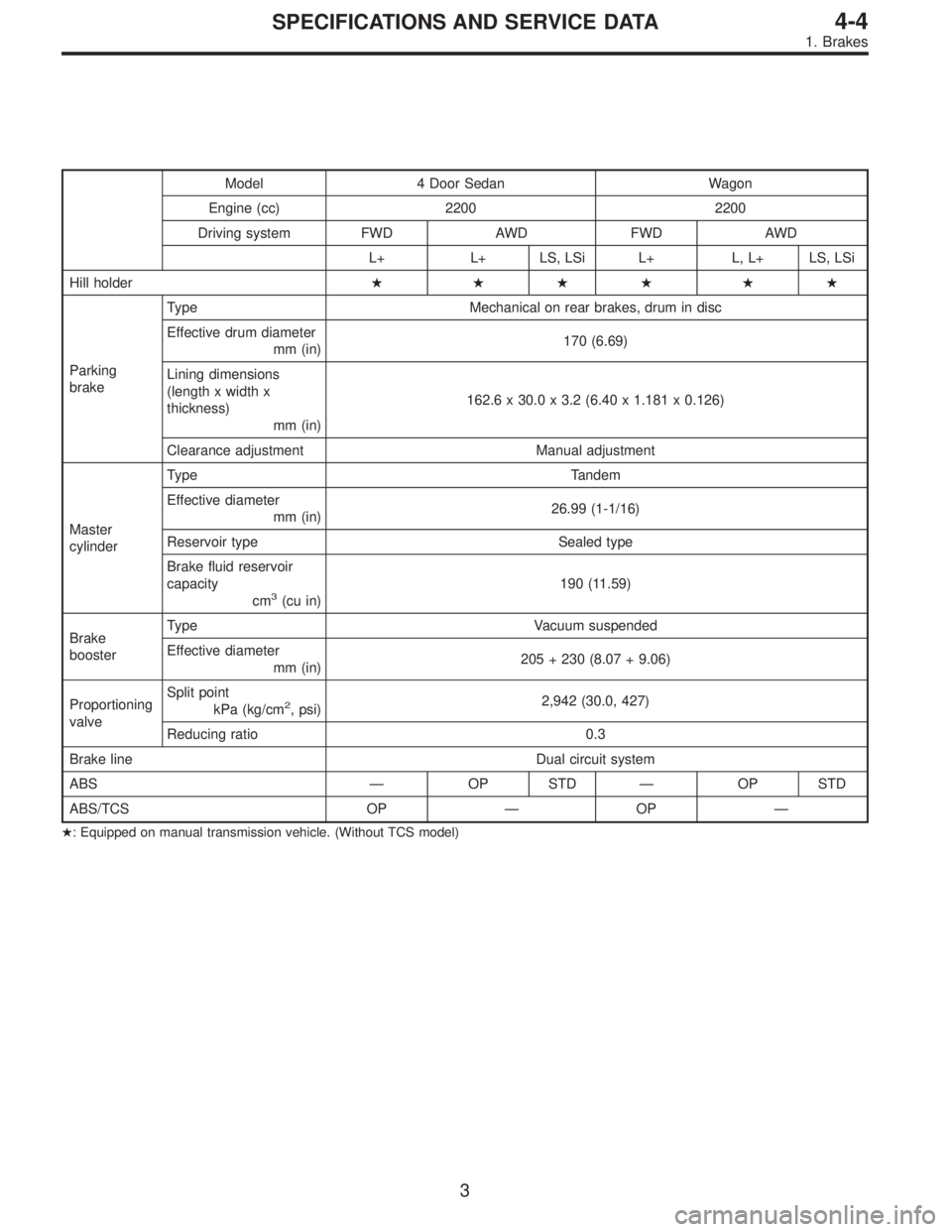
Model 4 Door Sedan Wagon
Engine (cc) 2200 2200
Driving system FWD AWD FWD AWD
L+ L+ LS, LSi L+ L, L+ LS, LSi
Hill holder� ��� ��
Parking
brakeType Mechanical on rear brakes, drum in disc
Effective drum diameter
mm (in)170 (6.69)
Lining dimensions
(length x width x
thickness)
mm (in)162.6 x 30.0 x 3.2 (6.40 x 1.181 x 0.126)
Clearance adjustment Manual adjustment
Master
cylinderType Tandem
Effective diameter
mm (in)26.99 (1-1/16)
Reservoir type Sealed type
Brake fluid reservoir
capacity
cm
3(cu in)190 (11.59)
Brake
boosterType Vacuum suspended
Effective diameter
mm (in)205 + 230 (8.07 + 9.06)
Proportioning
valveSplit point
kPa (kg/cm
2, psi)2,942 (30.0, 427)
Reducing ratio 0.3
Brake line Dual circuit system
ABS—OP STD—OP STD
ABS/TCS OP—OP—
�: Equipped on manual transmission vehicle. (Without TCS model)
3
4-4SPECIFICATIONS AND SERVICE DATA
1. Brakes
Page 719 of 2248
2. MODELS WITHOUT ABS AND ABS/TCS
Model Sedan Wagon
Engine (cc) 2200 2200
Driving system FWD AWD FWD AWD
BASE L+ L+ BASE L+ BRIGHTON L.L+
Front
brakeType Disc (Floating type, ventilated)
Effective disc diameter
mm (in)210 (8.27)
Disc thickness x Outer
diameter
mm (in)24 x 260 (0.94 x 10.24)
Effective cylinder
diameter
mm (in)57.2 (2.252)
Pad dimensions
(length x width x
thickness)
mm (in)112.4 x 44.3 x 11.0 (4.43 x 1.744 x 0.433)
Clearance adjustment Automatic adjustment
Rear
brakeType Drum (Leading-Trailing type)
Effective drum diameter
mm (in)228.6 (9)
Effective cylinder
diameter
mm (in)17.4 (0.685) 19.0 (0.748)
Lining dimensions
(length x width x
thickness)
mm (in)218.8 x 35.0 x 4.1 (8.61 x 1.378 x 0.161)
Clearance adjustment Automatic adjustment
4
4-4SPECIFICATIONS AND SERVICE DATA
1. Brakes
Page 720 of 2248
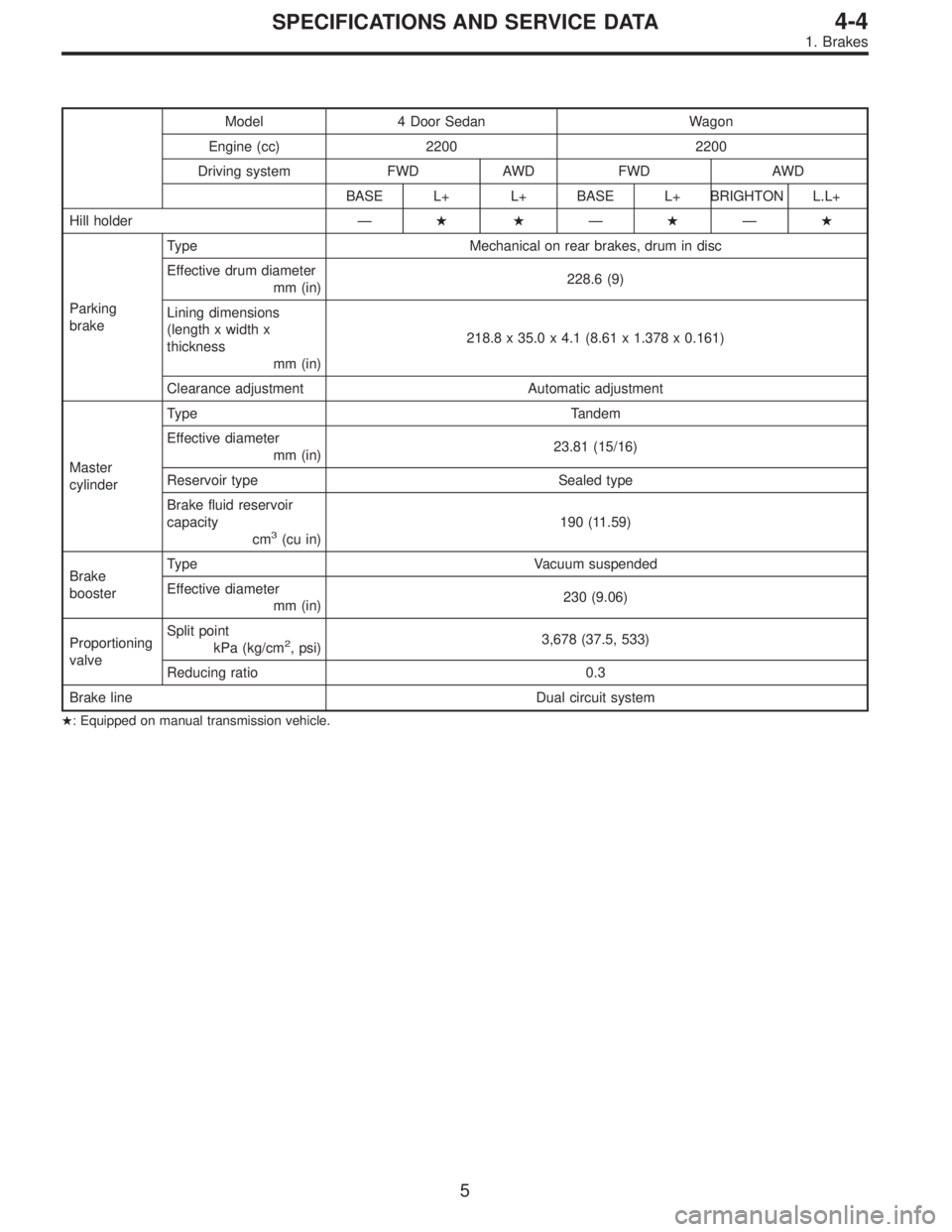
Model 4 Door Sedan Wagon
Engine (cc) 2200 2200
Driving system FWD AWD FWD AWD
BASE L+ L+ BASE L+ BRIGHTON L.L+
Hill holder—��—�—�
Parking
brakeType Mechanical on rear brakes, drum in disc
Effective drum diameter
mm (in)228.6 (9)
Lining dimensions
(length x width x
thickness
mm (in)218.8 x 35.0 x 4.1 (8.61 x 1.378 x 0.161)
Clearance adjustment Automatic adjustment
Master
cylinderType Tandem
Effective diameter
mm (in)23.81 (15/16)
Reservoir type Sealed type
Brake fluid reservoir
capacity
cm
3(cu in)190 (11.59)
Brake
boosterType Vacuum suspended
Effective diameter
mm (in)230 (9.06)
Proportioning
valveSplit point
kPa (kg/cm
2, psi)3,678 (37.5, 533)
Reducing ratio 0.3
Brake line Dual circuit system
�: Equipped on manual transmission vehicle.
5
4-4SPECIFICATIONS AND SERVICE DATA
1. Brakes
Page 721 of 2248
17 mm (0.67 in) 7.5 mm (0.295 in)
Disc thickness 24 mm (0.94 in) 22 mm (0.87 in)
Disc runout—0.075 mm (0.00")
B: SERVICE DATA
ITEM STANDARD SERVICE LIMIT
Front brakePad thickness
(including back metal)17 mm (0.67 in) 7.5 mm (0.295 in)
Disc thickness 24 mm (0.94 in) 22 mm (0.87 in)
Disc runout—0.075 mm (0.0030 in)
Rear brake (Disc type)Pad thickness
(including back metal)15 mm (0.59 in) 6.5 mm (0.256 in)
Disc thickness 10 mm (0.39 in) 8.5 mm (0.335 in)
Disc runout—0.10 mm (0.0039 in)
Rear brake (Drum type)Inside diameter 228.6 mm (9 in) 230.6 mm (9.08 in)
Lining thickness 4.1 mm (0.161 in) 1.5 mm (0.059 in)
Rear brake (Disc type
parking)Inside diameter 170 mm (6.69 in) 171 mm (6.73 in)
Lining thickness 3.2 mm (0.126 in) 1.5 mm (0.059 in)
Parking brake Lever stroke 7 to 8 notches/196N (20 kg,44 lb)
Without ABS and TCS With ABS and TCS
Brake boosterBrake pedal force Fluid pressure
Brake fluid pressure
without engine running147N
(15 kg, 33 lb)785 kPa
(8 kg/cm
2, 114 psi)588 kPa
(6 kg/cm2, 85 psi)
294N
(30kg, 66 lb)2,158 kPa
(22 kg/cm
2, 313 psi)1,667 kPa
(17 kg/cm2, 242 psi)
Brake fluid pressure with
engine running and
vacuum at 66.7 kPa (500
mmHg, 19.69 inHg)147N
(15 kg, 33 lb)5,492 kPa
(56 kg/cm
2, 796 psi)5,394 kPa
(55 kg/cm2, 782 psi)
294N
(30kg, 66 lb)8,434 kPa
(86 kg/cm
2, 1,223 psi)10,003 kPa
(102 kg/cm2, 1,450 psi)
C: RECOMMENDED BRAKE FLUID
FMVSS No. 116, fresh DOT3 or 4 brake fluid
CAUTION:
�Avoid mixing brake fluid of different brands to pre-
vent the fluid performance from degrading.
�When brake fluid is supplemented, be careful not to
allow any dust into the reservoir.
�Use fresh DOT3 or 4 brake fluid when replacing or
refilling the fluid.
D: BRAKE FLUID LEVEL INDICATOR
Reserve tank with level indicator:
Residual fluid quantity at light ON
Approx. 80 cm
3(4.88 cu in)
Tank capacity
190 cm
3(11.59 cu in)
6
4-4SPECIFICATIONS AND SERVICE DATA
1. Brakes
Page 759 of 2248
6. Brake Booster
A: REMOVAL
1) Remove or disconnect the following parts at engine
compartment.
(1) Disconnect connector for brake fluid level indicator.
(2) Remove brake pipes from master cylinder.
(3) Remove master cylinder installing nuts.
(4) Disconnect vacuum hose from brake booster.
2) Remove the following parts from the pedal bracket.
(1) Snap pin and clevis pin
(2) Four brake booster installing nuts
3) Remove brake booster while shunning brake pipes.
B4M0117A
B: INSTALLATION
1) Mount brake booster in position.
2) Connect operating rod to brake pedal with clevis pin
and snap pin.
�
1Clevis pin
�
2Snap pin
�
3Operating rod
G4M0420
3) Connect vacuum hose to brake booster.
4) Mount master cylinder onto brake booster.
5) Connect brake pipes to master cylinder.
6) Connect electric connector for brake fluid level indica-
tor.
43
4-4SERVICE PROCEDURE
6. Brake Booster
Page 761 of 2248

G4M0744
2. AIR TIGHTNESS CHECK
Start engine, and run it for 1 to 2 minutes, then turn it off.
Depress brake pedal several times applying the same
pedal force as that used in ordinary braking operations.
The pedal stroke should be greatest on the 1st depression,
and it should become smaller with each successive
depression. If no change occurs in the pedal height while
in a depressed state, brake booster is faulty.
NOTE:
�In the event of defective operation, inspect the condition
of the check valve and vacuum hose.
�Replace them if faulty and conduct the test again.
�If no improvement is observed, check precisely with
gauges.
G4M0914
3. OPERATION CHECK
1) With engine off, depress brake pedal several times
applying the same pedal force and make sure that the
pedal height does not vary with each depression of the
pedal.
2) With brake pedal depressed, start engine.
3) As engine starts, brake pedal should move slightly
toward the floor. If no change occurs in the pedal height,
brake booster is faulty.
NOTE:
If faulty, check precisely with gauges.
4. LOADED AIR TIGHTNESS CHECK
Depress brake pedal while engine is running, and turn off
engine while the pedal is still depressed. Keep the pedal
depressed for 30 seconds; if no change occurs in the pedal
height, brake booster is functioning normally; if the pedal
height increases, it is faulty.
NOTE:
If faulty, check precisely with gauges.
45
4-4SERVICE PROCEDURE
6. Brake Booster
Page 762 of 2248
 Start engine and keep it running un")
G4M0423
5. CHECKING WITH GAUGES
Connect gauges as shown in Figure. After bleeding air from
pressure gauges, proceed to each check.
G4M0746
6. AIR TIGHTNESS CHECK
1) Start engine and keep it running until a vacuum of 66.7
kPa (500 mmHg, 19.69 inHg) = point A is indicated on
vacuum gauge. Do not depress brake pedal.
2) Stop engine and watch the gauge. If the vacuum drop
range is less than 3.3 kPa (25 mmHg, 0.98 inHg) within 15
seconds after stopping engine, brake booster is functioning
properly.
If defective, the cause may be one of those listed below.
�Check valve malfunction
�Leak from vacuum hose
�Leak from the shell jointed portion or stud bolt welded
portion
�Damaged diaphragm
�Leak from valve body seal and bearing portion
�Leak from plate and seal assembly portion
�Leak from poppet valve assembly portion
G4M0747
7. LOADED AIR TIGHTNESS CHECK
1) Start engine and depress brake pedal with pedal force
of 196 N (20 kg, 44 lb). Keep engine running until a vacuum
of 66.7 kPa (500 mmHg, 19.69 inHg) = point B is indicated
on vacuum gauge while the pedal is still depressed.
2) Stop engine and watch vacuum gauge.
If the vacuum drop range is less than 3.3 kPa (25 mmHg,
0.98 inHg) within 15 seconds after stopping engine, brake
booster is functioning properly.
If defective, refer to“AIR TIGHTNESS CHECK”described
above.
46
4-4SERVICE PROCEDURE
6. Brake Booster
 2200 2200
Driving system FWD AWD FWD AWD
L+ L+ LS, LSi L+ L, L+ LS, LSi
Front
brakeType Disc (Floating type, ve")
 2200 2200
Driving system FWD AWD FWD AWD
BASE L+ L+ BASE L+ BRIGHTON L.L+
Front
brakeType Disc (Floating type, ventilated)
Effective dis")
 Remove or disconnect the following parts at engine
compartment.
(1) Disconnect connector for brake fluid level indicator.
(2) Remove brake pipes from master cylinder.
(3")