Page 815 of 2248
2. OPERATIONAL GUIDELINES OF THE TCS
SEQUENCE CONTROL WITH SELECT MONITOR
1) Connect select monitor to data link connector beside
driver’s seat heater unit.
2) Engine starts.
3) Put select monitor to TCS mode.
4) Put select monitor to FBI mode. Make sure code 11 is
indicated.
NOTE:
When trouble codes are stored in memory, repair the faulty
parts.
B4M0639
5) Press FD2 ENT key.
B4M0624
6) When the message shown in the figure is displayed,
press ENT key.
7) Checked portions will be displayed on select monitor.
B4M0627
8) When TCS sequence control cannot be started (by sys-
tem malfunction, etc.), the message shown in the figure will
be displayed.
NOTE:
Read the trouble codes. Repair faulty parts.
96
4-4SERVICE PROCEDURE
20. Hydraulic Unit for ABS/TCS System
Page 829 of 2248
G4M0319
2) If it is not in specified value, adjust it by turning adjust-
ing nut on engine side end of clutch cable.
Free play: L
3—4 mm (0.12—0.16 in)
Full stroke: A
25.5—27 mm (1.004—1.063 in)
3) Apply grease to connecting portion of clutch pedal and
clutch cable.
�
1Lock nut
�
2Adjusting nut
�
3Release fork
Lock nut tightening torque:
5.9±1.5 N⋅m (0.60±0.15 kg-m, 4.3±1.1 ft-lb)
G4M0320
3. ACCELERATOR PEDAL
Check pedal stroke and free play by operating accelerator
pedal by hand.
If it is not within specified value, adjust it by turning nut
connecting accelerator cable to throttle body.
Free play at pedal pad: L
1—4 mm (0.04—0.16 in)
Stroke at pedal pad: A
50—55 mm (1.97—2.17 in)
�
1Accelerator pedal
�
2Toe board
�
3Accelerator cable
Accelerator cable lock nut tightening torque:
14±4 N⋅m (1.4±0.4 kg-m, 10.1±2.9 ft-lb)
7
4-5SERVICE PROCEDURE
1. Pedal
Page 830 of 2248
B: REMOVAL
1. ACCELERATOR PEDAL (LHD MODEL)
1) Disconnect ground cable from battery.
2) Disconnect accelerator cable from throttle body.
CAUTION:
Be careful not to kink accelerator cable.
3) Remove instrument panel lower cover from instrument
panel, and connector.
G4M0322
4) Disconnect accelerator cable from accelerator pedal
lever.
G4M0335
5) Working inside engine compartment, remove casing
cap out of the toe board by turning it clockwise.
6) Pull out the cable from the toe board hole.
G4M0321
7) Remove accelerator pedal connecting bolt from accel-
erator pedal bracket.
8
4-5SERVICE PROCEDURE
1. Pedal
Page 840 of 2248
 Disconnect accelerator cable from connector inside
engine compartment first.
G2M0280
2) Remove lock nut from accelerator cable bracket.
3) Separate accelerator cable�
1from bracket, then")
A: REMOVAL
1) Disconnect accelerator cable from connector inside
engine compartment first.
G2M0280
2) Remove lock nut from accelerator cable bracket.
3) Separate accelerator cable�
1from bracket, then unlock
inner cable.
4) Remove cable end from throttle cam using your finger-
tips.
CAUTION:
Be careful not to bend inner cable.
5) Disconnect cable end from accelerator cable bracket
inside driver compartment.
6) Remove clip inside engine compartment.
G4M0335
7) Working inside engine compartment, remove the casing
cap out of the toe board by turning it clockwise.
8) Pull out the cable from the toe board hole.
B: INSTALLATION
1) Installation is in the reverse order of removal proce-
dures.
CAUTION:
�Be careful not to kink accelerator cable.
�Make sure that holder and casing cap are securely
connected.
B4M0159A
�1Casing cap
�
2Accelerator cable
�
3Toe board
�
4Accelerator pedal bracket
�
5Holder
2) Adjustment after cable installation.
18
4-5SERVICE PROCEDURE
3. Accelerator Cable
Page 851 of 2248
1. Supplemental Restraint System
“Airbag”
Airbag system wiring harness is routed near the instrument
panel, heater unit, blower motor and control unit.
CAUTION:
�All Airbag system wiring harness and connectors
are colored yellow. Do not use electrical test equip-
ment on these circuit.
�Be careful not to damage Airbag system wiring har-
ness when servicing the instrument panel, heater unit,
blower motor and control unit.
2. Heater Unit
A: REMOVAL AND INSTALLATION
1) Disconnect GND cable from battery.
2) Remove heater hoses (inlet, outlet) in engine compart-
ment.
NOTE:
Drain as much coolant from heater unit as possible, and
plug disconnected hose with cloth.
3) Remove instrument panel.
4) Remove steering support beam.
5) Remove evaporator. (With A/C model)
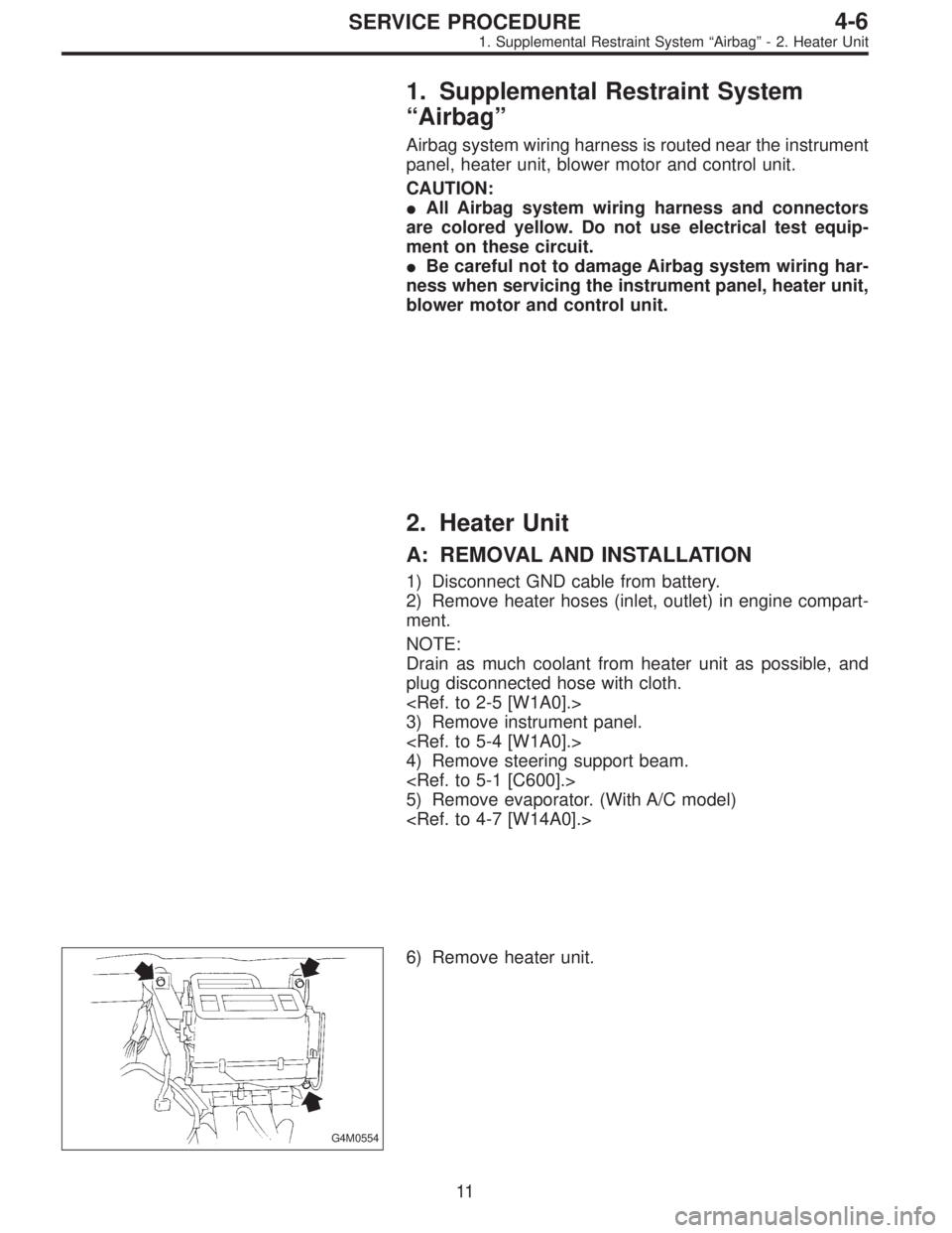
G4M0554
6) Remove heater unit.
11
4-6SERVICE PROCEDURE
1. Supplemental Restraint System“Airbag”- 2. Heater Unit
Page 852 of 2248
1. Supplemental Restraint System
“Airbag”
Airbag system wiring harness is routed near the instrument
panel, heater unit, blower motor and control unit.
CAUTION:
�All Airbag system wiring harness and connectors
are colored yellow. Do not use electrical test equip-
ment on these circuit.
�Be careful not to damage Airbag system wiring har-
ness when servicing the instrument panel, heater unit,
blower motor and control unit.
2. Heater Unit
A: REMOVAL AND INSTALLATION
1) Disconnect GND cable from battery.
2) Remove heater hoses (inlet, outlet) in engine compart-
ment.
NOTE:
Drain as much coolant from heater unit as possible, and
plug disconnected hose with cloth.
3) Remove instrument panel.
4) Remove steering support beam.
5) Remove evaporator. (With A/C model)
G4M0554
6) Remove heater unit.
11
4-6SERVICE PROCEDURE
1. Supplemental Restraint System“Airbag”- 2. Heater Unit
Page 879 of 2248
 Be certain that goggles and gloves are worn.
2) If bulk refr")
G4M0596
7. Evacuating and Charging
The following points should be kept in mind when evacu-
ating and charging with a manifold gauge set.
1) Be certain that goggles and gloves are worn.
2) If bulk refrigerant [13.6 kg (30 lb) canister] is used, be
certain to weigh the charge amount carefully, using the
correct equipment, to avoid overcharging the system.
3) The charging procedure described in this section
begins by chargingliquidrefrigerant into the high- pres-
sure side of the systemwith the engine off.The proce-
dure is completed by charging refrigerantvaporinto the
low-pressure side of the system with the engine running.
CAUTION:
Never open the high-pressure manifold valve when the
engine is running.
G4M0597
1. CONNECT THE GAUGE SET
1) Close the high- and low-pressure manifold valves.
2) Attach the low-pressure manifold hose to the low- pres-
sure service port on the vehicle. Check the low- pressure
gauge. If more than 68.6 kPa (0.70 kg/cm
2, 10 psi) is
indicated, discharge the system prior to charging.
3) Attach the high-pressure manifold hose to the high-
pressure service port on the vehicle.
4) Connect the center hose from the manifold to the
vacuum pump.
5) Turn on the vacuum pump.
6) Slowly open the low-pressure manifold valve.
7) When the low-pressure gauge reaches approximately
66.43 kPa (498.3 mmHg, 19.62 inHg), slowly open the
high-pressure manifold valve.
G4M0598
8) Maintain a minimum vacuum level of 100.56 kPa (754.4
mmHg, 29.70 inHg) for a minimum of 15 minutes on a new
system or 30 minutes for an in-service system.
NOTE:
The gauge will read 4 kPa (25 mmHg, 1 inHg) less for
every 304.8 m (1,000 ft) above sea level.
19
4-7SERVICE PROCEDURE
7. Evacuating and Charging
Page 881 of 2248
 Connect a tachometer to the engine.
2)With the engine off, start charging by slowly opening
the high-pressure manifold valve.
NOTE:
The initial cha")
G4M0604
4. INITIAL CHARGING THROUGH THE HIGH SIDE
1) Connect a tachometer to the engine.
2)With the engine off, start charging by slowly opening
the high-pressure manifold valve.
NOTE:
The initial charge rate can be increased by immersing the
can in lukewarm [Below 38°C (100°F)] water for a short
time.
G4M0605
5. CHECK THE GAUGE READINGS
When both the high- and low-pressure gauge readings are
about equal, or the HFC-134a source is empty, or the sys-
tem has been filled to specifications, close the high- pres-
sure manifold valve.
6. ADD ADDITIONAL CANS
If the HFC-134a source is exhausted, first close the high-
pressure manifold valve, second, close the can tap valve,
then slowly purge the refrigerant from the service hose by
loosening the fitting at the can tap. Repeat steps 15
through 19 as necessary.
G4M0606
7. COMPLETE CHARGING THROUGH THE LOW SIDE
1) Verify that the high-pressure manifold valve is closed
(should have already been closed).
2) Verify that the low-pressure manifold valve is closed
(should have already been closed).
G4M0607
3) With the A/C switch off and the windows rolled down,
start the engine and run at idle rpm.
4) Set the A/C controls on maximum cool and set the
blower speed on the highest setting.
5) Quickly turn the A/C switch on-off-on-off a few times to
prevent initial compressor damage due to“load shock.”
Finish this operation with the A/C switch in the ON position.
6) Raise engine rpm to approximately 1,500 rpm.
21
4-7SERVICE PROCEDURE
7. Evacuating and Charging
![SUBARU LEGACY 1995 Service Repair Manual 2. OPERATIONAL GUIDELINES OF THE TCS
SEQUENCE CONTROL WITH SELECT MONITOR
1) Connect select monitor to data link connector beside
driver’s seat heater unit. <Ref. to [W19D0] step 1).>
2) Engine star](/manual-img/17/57432/w960_57432-814.png "SUBARU LEGACY 1995 Service Repair Manual 2. OPERATIONAL GUIDELINES OF THE TCS
SEQUENCE CONTROL WITH SELECT MONITOR
1) Connect select monitor to data link connector beside
driver’s seat heater unit. <Ref. to [W19D0] step 1).>
2) Engine star")
 If it is not in specified value, adjust it by turning adjust-
ing nut on engine side end of clutch cable.
Free play: L
3—4 mm (0.12—0.16 in)
Full stroke: A
25.5—27 mm (1.004—1.063 i")

1) Disconnect ground cable from battery.
2) Disconnect accelerator cable from throttle body.
CAUTION:
Be careful not to kink accelerator cable.
3) Remove in")