Page 1095 of 2248
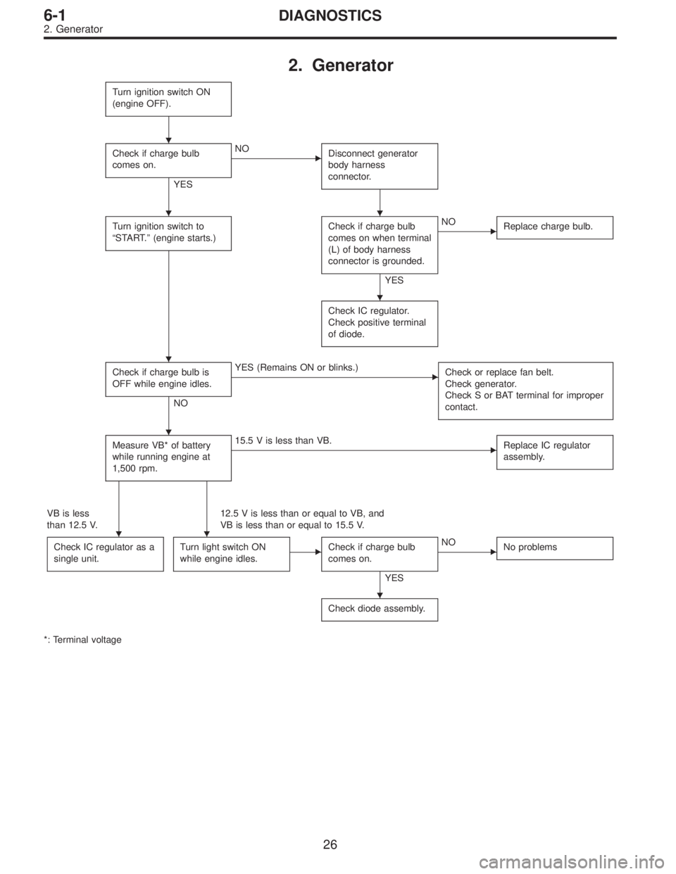
2. Generator
Turn ignition switch ON
(engine OFF).
Check if charge bulb
comes on.
YES
�NO
Disconnect generator
body harness
connector.
Turn ignition switch to
“START.”(engine starts.)Check if charge bulb
comes on when terminal
(L) of body harness
connector is grounded.
YES
�NO
Replace charge bulb.
Check IC regulator.
Check positive terminal
of diode.
Check if charge bulb is
OFF while engine idles.
NO
�YES (Remains ON or blinks.)
Check or replace fan belt.
Check generator.
Check S or BAT terminal for improper
contact.
Measure VB* of battery
while running engine at
1,500 rpm.�15.5 V is less than VB.
Replace IC regulator
assembly.
VB is less
than 12.5 V.12.5 V is less than or equal to VB, and
VB is less than or equal to 15.5 V.
Check IC regulator as a
single unit.
Turn light switch ON
while engine idles.�Check if charge bulb
comes on.
YES
�NO
No problems
Check diode assembly.
*: Terminal voltage
�
��
�
�
�
��
�
26
6-1DIAGNOSTICS
2. Generator
Page 1096 of 2248
, 100 minutes (AT)
Cold cranking ampere 430 amperes (MT), 490 amperes (AT)
Fuse10 A, 15 A, 20 A
Combination
meterSpeedometer")
1. Body Electrical
A: SPECIFICATIONS
BatteryReserve capacity 82 minutes (MT), 100 minutes (AT)
Cold cranking ampere 430 amperes (MT), 490 amperes (AT)
Fuse10 A, 15 A, 20 A
Combination
meterSpeedometer Electric pulse type
Tachometer Electric impulse type
Water temperature gauge Thermistor cross coil type
Fuel gauge Resistance cross coil type
Charge indicator light 12 V—1.4 W
Brake fluid level warning/parking brake indicator light 12 V—1.4 W
AT oil temperature warning light (AWD only) 12 V—1.4 W
A.B.S. warning light 12 V—1.4 W
CHECK ENGINE warning light
(Malfunction indicator lamp)12 V—1.4 W
Oil pressure warning light 12 V—1.4 W
AIRBAG system warning light 12 V—1.4 W
Low fuel warning light 12 V—3W
FWD indicator light 12 V—1.4 W
TCS warning light 12 V—1.4 W
TCS indicator light 12 V—1.4 W
Turn signal indicator light 12 V—1.4 W (2 pieces)
Seat belt warning light 12 V—1.4 W
Door open warning light 12 V—1.4 W
Headlight beam indicator light 12 V—1.4 W
Meter illumination light12 V—3 W (2 pieces)
12 V—3.4 W (4 pieces)
Headlight 12 V—60/55 W (Halogen)
Front clearance light 12 V—5W
Turn signal lightFront 12 V—21 W
Rear 12 V—21 W
Tail/Stop light 12 V—5/21 W
Back-up light 12 V—21 W
High-mount stop light12 V—18 W (SEDAN), 12 V—13 W
(WAGON)
License plate light 12 V—5W
Room light 12 V—8W
Trunk room light (SEDAN) 12 V—5W
Luggage room light (WAGON) 12 V—5W
Spot light 12 V—8 W (2 pieces)
Glove box light 12 V—3.4 W
Ash tray illumination light 12 V—1.7 W
Selector lever illumination light (AT model) 12 V—1.7 W
2
6-2SPECIFICATIONS
1. Body Electrical
Page 1106 of 2248
 Look at the beam angle gauge (vertical movement).
The bubble on the gauge should not deviate from the cen-
ter of the gauge.
B6M0337A
3) Look at the beam angle gauge (horizontal movement).")
B6M0336A
2) Look at the beam angle gauge (vertical movement).
The bubble on the gauge should not deviate from the cen-
ter of the gauge.
B6M0337A
3) Look at the beam angle gauge (horizontal movement).
The center mark (the red line on the inner scale) should not
deviate from the black line on the outer case.
B: REMOVAL AND INSTALLATION
1. HEADLIGHT BULB
1) Disconnect the connector from inside of the engine
compartment.
2) Remove rubber cap.
3) Remove the light bulb retaining spring to remove the
bulb.
4) Replace the bulb with a new one and hook the spring.
5) Attach the rubber cap and connect the connector.
M6A0139
CAUTION:
�Since the tungsten halogen bulb operates at high
temperature, dirt and oil on the bulb surface decreases
the bulb’s useful life. When replacing the bulb, hold the
flange portion and do not touch the glass portion.
M6A0140
�Attach the rubber cap with letters TOP on the top so
that the drain hole will be on the lower side.
�To keep water out, correctly engage the groove por-
tion of the rubber cap.
9
6-2SERVICE PROCEDURE
4. Headlight
Page 1115 of 2248
6. Turn Signal and Hazard Warning
Light
A: REMOVAL AND INSTALLATION
1. FRONT TURN SIGNAL LIGHT
Refer to 6-2 [W4B2] as for removal and installation of front
turn signal light.
NOTE:
The front turn signal light is united with headlight assem-
bly.
2. REAR COMBINATION LIGHT
Refer to 6-2 [W5A1] as for removal and installation of rear
combination light.
3. COMBINATION SWITCH
Refer to 6-2 [W4B3] as for removal and installation of com-
bination switch.
B6M0063
4. HAZARD SWITCH
1) Remove center panel from instrument panel.
5-4 [W1A0].>
2) Disconnect connector of hazard switch from body har-
ness.
3) Remove hazard switch from center panel.
B6M0343A
5. TURN SIGNAL AND HAZARD UNIT
1) Remove instrument panel lower cover.
2) Remove engine hood opener lever bracket.
3) Disconnect connector of turn signal and hazard unit.
4) Remove screw, and then remove turn signal and haz-
ard unit from bracket.
18
6-2SERVICE PROCEDURE
6. Turn Signal and Hazard Warning Light
Page 1121 of 2248
B6M0107A
B: REMOVAL AND INSTALLATION
1. BLADE
Pull out blade following the arrow direction from arm while
pushing up locking clip.
G6M0118
2. WIPER ARM
1) Open engine hood.
2) Remove cap of wiper arm installation nut.
3) Remove the nut which secures wiper arm.
4) Remove wiper arm.
5) Installation is in the reverse order of removal.
NOTE:
Remove metal sludge from the wiper arm fixture before
installing it.
Tightening torque:
20±3 N⋅m (2.0±0.3 kg-m, 14.5±2.2 ft-lb)
3. WIPER MOTOR AND LINK
1) Detach weatherstrip and cowl panel.
[W10A0].>
NOTE:
Apply silicone oil or soap water to both sides of cowl net to
facilitate removal.
B6M0108
2) Disconnect connector of wiper motor.
3) Remove motor attaching bolts.
Tightening torque:
5.9±1.5 N⋅m (0.6±0.15 kg-m, 4.3±1.1 ft-lb)
23
6-2SERVICE PROCEDURE
10. Front Wiper and Washer
Page 1122 of 2248
 Remove wiper link from back side of wiper motor using
a screwdriver inserted into service hole in front panel.
CAUTION:
Do not pry wiper link off forcefully as this may scratch
vehicle body.
5) Rem")
4) Remove wiper link from back side of wiper motor using
a screwdriver inserted into service hole in front panel.
CAUTION:
Do not pry wiper link off forcefully as this may scratch
vehicle body.
5) Remove wiper motor.
6) Separate the driver’s side wiper link from back side of
the passenger’s side wiper sleeve unit.
G6M0021
7) Remove nuts which secure sleeve unit.
Tightening torque:
5.9±1.5 N⋅m (0.6±0.15 kg-m, 4.3±1.1 ft-lb)
G6M0121
8) Remove wiper link from service hole in front panel.
B6M0109A
4. WASHER TANK AND WASHER MOTOR
1) Remove washer tank attaching bolts.
2) Disconnect connectors of washer motors.
3) Disconnect washer hoses from each washer motor.
4) Remove washer tank and washer motor as an unit.
5) Separate washer motor from washer tank.
B6M0110A
5. NOZZLE
1) Disconnect washer hose from nozzle.
2) Push nozzle clip in direction A as shown in figure.
3) Remove nozzle from engine hood.
CAUTION:
Do not pry nozzle off forcefully as this may scratch
vehicle body.
24
6-2SERVICE PROCEDURE
10. Front Wiper and Washer
Page 1132 of 2248
G6M0112
2. DEFOGGER RELAY
Check continuity between terminals as indicated in table
below, when connecting the battery to terminal No. 1 and
No. 3.
When current flows.Between terminals
No. 2 and No. 4Continuity exists.
When current does not flow.Between terminals
No. 2 and No. 4Continuity does not
exist.
Between terminals
No. 1 and No. 3Continuity exists.
G6M0135
3. HEAT WIRES
1) Start the engine so that battery is being charged.
2) Turn defogger switch to ON.
3) Check each heat wire at its center position for discon-
tinuity by setting direct current voltmeter.
Normal indication is about 6 volts.
G6M0136
NOTE:
When measuring voltage, wind a piece of tin foil around the
tip of the tester probe and press the foil against the wire
with your finger.
32
6-2SERVICE PROCEDURE
12. Rear Window Defogger
Page 1135 of 2248
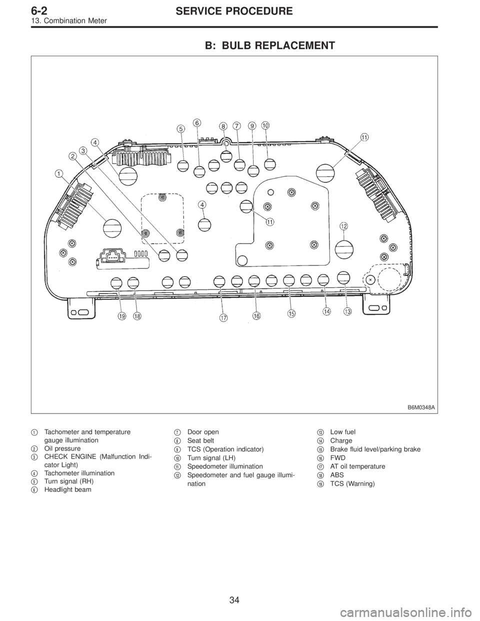
B: BULB REPLACEMENT
B6M0348A
�1Tachometer and temperature
gauge illumination
�
2Oil pressure
�
3CHECK ENGINE (Malfunction Indi-
cator Light)
�
4Tachometer illumination
�
5Turn signal (RH)
�
6Headlight beam�
7Door open
�
8Seat belt
�
9TCS (Operation indicator)
�
10Turn signal (LH)
�
11Speedometer illumination
�
12Speedometer and fuel gauge illumi-
nation�
13Low fuel
�
14Charge
�
15Brake fluid level/parking brake
�
16FWD
�
17AT oil temperature
�
18ABS
�
19TCS (Warning)
34
6-2SERVICE PROCEDURE
13. Combination Meter
![SUBARU LEGACY 1995 Service Repair Manual 6. Turn Signal and Hazard Warning
Light
A: REMOVAL AND INSTALLATION
1. FRONT TURN SIGNAL LIGHT
Refer to 6-2 [W4B2] as for removal and installation of front
turn signal light.
NOTE:
The front turn sign](/manual-img/17/57432/w960_57432-1114.png "SUBARU LEGACY 1995 Service Repair Manual 6. Turn Signal and Hazard Warning
Light
A: REMOVAL AND INSTALLATION
1. FRONT TURN SIGNAL LIGHT
Refer to 6-2 [W4B2] as for removal and installation of front
turn signal light.
NOTE:
The front turn sign")
 Open engine hood.
2) Remove cap of wiper arm")