Page 874 of 2248
Tools and Equipment Description
�THERMOMETER
PocketTHERMOMETERSare available from either industrial
hardware store or commercial refrigeration supply houses.
G4M0578
�ELECTRONIC LEAK DETECTOR
AnELECTRONIC LEAK DETECTORcan be obtained from
either a specialty tool supply or an A/C equipment supplier.
G4M0579
�WEIGHT SCALE
AWEIGHT SCALEsuch as an electronic charging scale or a
bathroom scale with digital display will be needed if a 13.6 kg
(30 lb) refrigerant container is used.
G4M0580
14
4-7SERVICE PROCEDURE
3. Tools and Equipment
Page 880 of 2248

G4M0599
2. PERFORM A VACUUM LEAK TEST
1) After 15 minutes (or more) of evacuation, close the
high-pressure manifold valve.
2) Close the low-pressure manifold valve.
3) Turn off the vacuum pump.
G4M0600
4) Note the low side gauge reading.
5) After 5 minutes, re-check the low-pressure gauge read-
ing.
If the vacuum level has changed more than 4 kPa (25
mmHg, 1 inHg), perform an HFC-134a leak test.
If the vacuum reading is about the same as noted in step
2-4), continue on to step 2-6).
G4M0980
6) Carefully attach the can tap to the refrigerant can by
following the can tap manufacturer’s instructions.
7) Disconnect the center manifold hose from the vacuum
pump and connect the hose to the tap valve.
G4M0981
8) If a 13.6 kg (30 lb) container of refrigerant is used a
weight scale will be needed. This scale is to determine the
amount of refrigerant that is used.
Connect the center hose from the manifold to the valve.
Place the 13.6 kg (30 lb) container on the scale, valve end
down.
G4M0603
3. PURGE THE CENTER HOSE
1) Verify that all three hose connections are tight at the
manifold gauge set.
2) Open the valve on the HFC-134a source.
3)With safety equipment in place (goggles and
gloves), use extreme cautionand loosen the center hose
connection at the manifold and allow the HFC-134a to
escape for no more than two or three seconds, then quickly
retighten the hose fitting at the manifold.
20
4-7SERVICE PROCEDURE
7. Evacuating and Charging
Page 949 of 2248

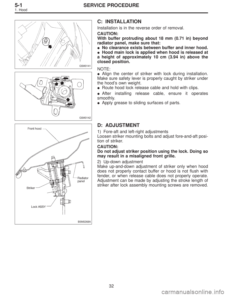
G5M0141
C: INSTALLATION
Installation is in the reverse order of removal.
CAUTION:
With buffer protruding about 18 mm (0.71 in) beyond
radiator panel, make sure that:
�No clearance exists between buffer and inner hood.
�Hood main lock is applied when hood is released at
a height of approximately 10 cm (3.94 in) above the
closed position.
G5M0142
NOTE:
�Align the center of striker with lock during installation.
Make sure safety lever is properly caught by striker under
the hood’s own weight.
�Route hood lock release cable and hold with clips.
�After installing release cable, ensure it operates
smoothly.
�Apply grease to sliding surfaces of parts.
B5M0268A
D: ADJUSTMENT
1) Fore-aft and left-right adjustments
Loosen striker mounting bolts and adjust fore-and-aft posi-
tion of striker.
CAUTION:
Do not adjust striker position using the lock. Doing so
may result in a misaligned front grille.
2) Up-down adjustment
Make up-and-down adjustment of striker only when hood
does not properly contact buffer or hood is not flush with
fender, or when release cable does not properly operate.
Adjustment can be made by adjusting the stroke length of
striker after lock assembly mounting screws are removed.
32
5-1SERVICE PROCEDURE
1. Hood
Page 950 of 2248
G5M0144
2. Trunk Lid
A: REMOVAL
1. TRUNK LID
1) Open trunk lid.
2) Remove trunk lid mounting bolts and detach trunk lid
from hinges.
G5M0145
2. TORSION BAR
1) Open trunk lid. Remove torsion bars from hinge links
using ST.
ST 927780000 REMOVER
CAUTION:
Be careful because torsion bar quickly swings back
when released.
2) Remove the left and right torsion bars.
WARNING:
Be careful because trunk lid drops under its own
weight when torsion bars are removed.
G5M0146
3. TRUNK LID LOCK ASSEMBLY AND KEY
CYLINDER
1) Remove rod of lock assembly from rod holder of key
lock assembly.
2) Remove nuts which hold lock assembly and remove
lock assembly.
NOTE:
�Always remove rear skirt trim panel beforehand, if so
equipped.
�Be careful not to bend opener cable.
B5M0269A
3) Remove rod holder and detach key cylinder from trunk
lid.
33
5-1SERVICE PROCEDURE
2. Trunk Lid
Page 1423 of 2248

OBD0283
Y: DTC P0325
—KNOCK SENSOR CIRCUIT MALFUNCTION
(KNOCK)—
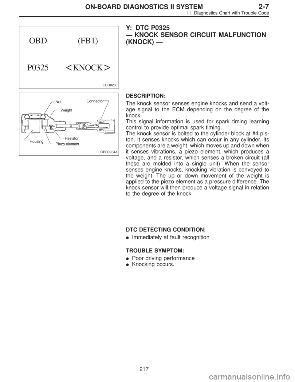
OBD0284A
DESCRIPTION:
The knock sensor senses engine knocks and send a volt-
age signal to the ECM depending on the degree of the
knock.
This signal information is used for spark timing learning
control to provide optimal spark timing.
The knock sensor is bolted to the cylinder block at #4 pis-
ton. It senses knocks which can occur in any cylinder. Its
components are a weight, which moves up and down when
it senses vibrations, a piezo element, which produces a
voltage, and a resistor, which senses a broken circuit (all
these are molded into a single unit). When the sensor
senses engine knocks, knocking vibration is conveyed to
the weight. The up or down movement of the weight is
applied to the piezo element as a pressure difference. The
knock sensor will then produce a voltage signal in relation
to the degree of the knock.
DTC DETECTING CONDITION:
�Immediately at fault recognition
TROUBLE SYMPTOM:
�Poor driving performance
�Knocking occurs.
217
2-7ON-BOARD DIAGNOSTICS II SYSTEM
11. Diagnostics Chart with Trouble Code
Page:
< prev 1-8 9-16 17-24