Page 549 of 2248
B4M0196A
3) Turn trailing link upside down. Press ST plunger in the
direction opposite that outlined in step 2) until bushing is
correctly positioned in trailing link.
ST 927730000 INSTALLER & REMOVER SET
E: INSTALLATION
Installation is in the reverse order of removal.
CAUTION:
Always tighten rubber bushing location when wheels
are in full contact with the ground and vehicle is at
curb weight condition.
NOTE:
Check wheel alignment and adjust if necessary.
32
4-1SERVICE PROCEDURE
7. Rear Trailing Link
Page 555 of 2248
E: INSTALLATION
To install, reverse removal procedures, reading the follow-
ing instructions.
CAUTION:
�Always tighten rubber bushing when wheels are in
full contact with the ground and vehicle is at curb
weight condition.
�Tighten nut when installing adjusting bolt.
�Replace self-locking nut and DOJ circlip with new
ones.
NOTE:
�Lateral link washers for FWD and AWD models can be
identified by colors, as follows:
Olive (FWD model)
Gold (AWD model)
�Check wheel alignment and adjust if necessary.
38
4-1SERVICE PROCEDURE
8. Lateral Link
Page 560 of 2248
B: INSPECTION
Check removed parts for wear, damage and cracks, and
correct or replace if defective.
C: INSTALLATION
Installation is in reverse order of removal procedure.
CAUTION:
�Discard loosened self-locking nut and replace with a
new one.
�Always tighten nut (not adjusting bolt), when tight-
ening adjusting bolt.
�Always tighten rubber bushing when wheels are in
full contact with the ground and vehicle is at curb
weight condition.
NOTE:
Check wheel alignment and adjust if necessary.
43
4-1SERVICE PROCEDURE
10. Rear Crossmember (FWD Model)
Page 562 of 2248
G4M0544
5) Place transmission jack under rear crossmember.
G4M0545
6) Remove bolts securing crossmember to vehicle body,
and remove crossmember.
7) Scribe an alignment mark on rear lateral link cam bolt
and crossmember.
8) Remove four bolts securing front and rear lateral links
to crossmember by loosening nuts.
B: INSPECTION
Check removed parts for damage and cracks, and correct
or replace if defective.
C: INSTALLATION
1) Install in reverse order of removal.
2) For installation and tightening torque of rear differential,
refer to 3-4 [W2F0].
CAUTION:
Always tighten rubber bushing when wheels are in full
contact with the ground and vehicle is at curb weight
condition.
NOTE:
Check wheel alignment and adjust if necessary.
45
4-1SERVICE PROCEDURE
11. Rear Crossmember (AWD Model)
Page 566 of 2248
5. APPLICATION TABLE
Model Power unitFront drive shaft
Rear drive shaft
5MT 4AT
FWD 2200 cc 95AC-25 87AC-25—
AWD 2200 cc 82AC-25 82AC-25 79AC-RH, 79AC-LH
B: SERVICE DATA
Wheel balancing Standard Service limit
Dynamic unbalance Less than 5 g (0.18 oz)
Balance weight part number
(For steel wheel)Weight g (oz)
28101AA001 5 (0.18)
28101AA011 10 (0.35)
28101AA021 15 (0.53)
28101AA031 20 (0.71)
28101AA041 25 (0.88)
28101AA051 30 (1.06)
28101AA061 35 (1.23)
28101AA071 40 (1.41)
28101AA081 45 (1.59)
28101AA091 50 (1.76)
28101AA101 55 (1.94)
28101AA111 60 (2.12)
Balance weight part number
(For aluminum wheel)Weight g (oz)
23141GA462 5 (0.18)
23141GA472 10 (0.35)
23141GA482 15 (0.53)
23141GA492 20 (0.71)
23141GA502 25 (0.88)
23141GA512 30 (1.06)
23141GA522 35 (1.23)
23141GA532 40 (1.41)
23141GA542 45 (1.59)
23141GA552 50 (1.76)
—55 (1.94)
23141GA572 60 (2.12)
4
4-2SPECIFICATIONS AND SERVICE DATA
1. Wheels and Axles
Page 613 of 2248

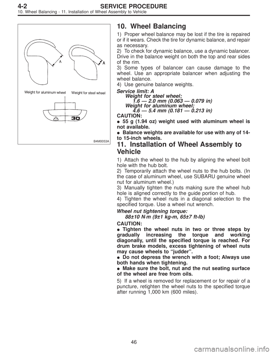
B4M0053A
10. Wheel Balancing
1) Proper wheel balance may be lost if the tire is repaired
or if it wears. Check the tire for dynamic balance, and repair
as necessary.
2) To check for dynamic balance, use a dynamic balancer.
Drive in the balance weight on both the top and rear sides
of the rim.
3) Some types of balancer can cause damage to the
wheel. Use an appropriate balancer when adjusting the
wheel balance.
4) Use genuine balance weights.
Service limit: A
Weight for steel wheel;
1.6—2.0 mm (0.063—0.079 in)
Weight for aluminum wheel;
4.6—5.4 mm (0.181—0.213 in)
CAUTION:
�55 g (1.94 oz) weight used with aluminum wheel is
not available.
�Balance weights are available for use with any of 14-
to 15-inch wheels.
11. Installation of Wheel Assembly to
Vehicle
1) Attach the wheel to the hub by aligning the wheel bolt
hole with the hub bolt.
2) Temporarily attach the wheel nuts to the hub bolts. (In
the case of aluminum wheel, use SUBARU genuine wheel
nut for aluminum wheel.)
3) Manually tighten the nuts making sure the wheel hub
hole is aligned correctly to the guide portion of hub.
4) Tighten the wheel nuts in a diagonal selection to the
specified torque. Use a wheel nut wrench.
Wheel nut tightening torque:
88±10 N⋅m (9±1 kg-m, 65±7 ft-lb)
CAUTION:
�Tighten the wheel nuts in two or three steps by
gradually increasing the torque and working
diagonally, until the specified torque is reached. For
drum brake models, excess tightening of wheel nuts
may cause wheels to “judder”.
�Do not depress the wrench with a foot; Always use
both hands when tightening.
�Make sure the bolt, nut and the nut seating surface
of the wheel are free from oils.
5) If a wheel is removed for replacement or for repair of a
puncture, retighten the wheel nuts to the specified torque
after running 1,000 km (600 miles).
46
4-2SERVICE PROCEDURE
10. Wheel Balancing - 11. Installation of Wheel Assembly to Vehicle
Page 614 of 2248

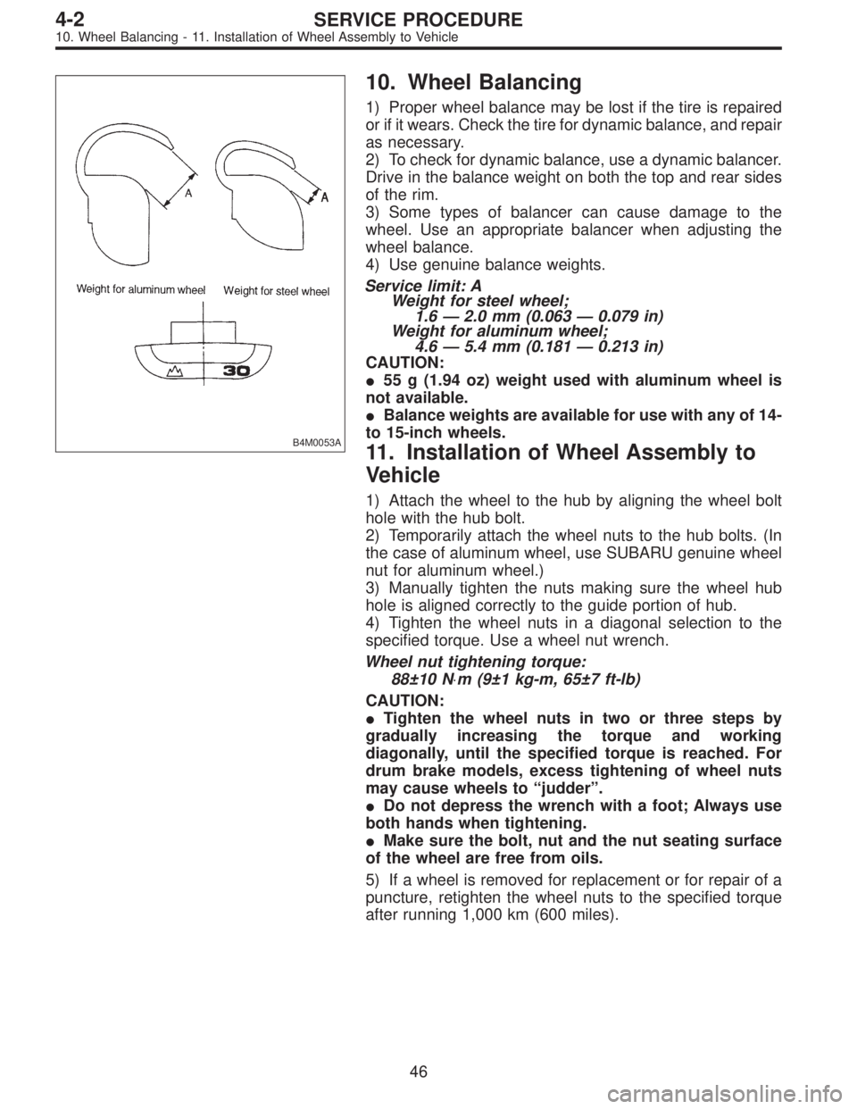
B4M0053A
10. Wheel Balancing
1) Proper wheel balance may be lost if the tire is repaired
or if it wears. Check the tire for dynamic balance, and repair
as necessary.
2) To check for dynamic balance, use a dynamic balancer.
Drive in the balance weight on both the top and rear sides
of the rim.
3) Some types of balancer can cause damage to the
wheel. Use an appropriate balancer when adjusting the
wheel balance.
4) Use genuine balance weights.
Service limit: A
Weight for steel wheel;
1.6—2.0 mm (0.063—0.079 in)
Weight for aluminum wheel;
4.6—5.4 mm (0.181—0.213 in)
CAUTION:
�55 g (1.94 oz) weight used with aluminum wheel is
not available.
�Balance weights are available for use with any of 14-
to 15-inch wheels.
11. Installation of Wheel Assembly to
Vehicle
1) Attach the wheel to the hub by aligning the wheel bolt
hole with the hub bolt.
2) Temporarily attach the wheel nuts to the hub bolts. (In
the case of aluminum wheel, use SUBARU genuine wheel
nut for aluminum wheel.)
3) Manually tighten the nuts making sure the wheel hub
hole is aligned correctly to the guide portion of hub.
4) Tighten the wheel nuts in a diagonal selection to the
specified torque. Use a wheel nut wrench.
Wheel nut tightening torque:
88±10 N⋅m (9±1 kg-m, 65±7 ft-lb)
CAUTION:
�Tighten the wheel nuts in two or three steps by
gradually increasing the torque and working
diagonally, until the specified torque is reached. For
drum brake models, excess tightening of wheel nuts
may cause wheels to “judder”.
�Do not depress the wrench with a foot; Always use
both hands when tightening.
�Make sure the bolt, nut and the nut seating surface
of the wheel are free from oils.
5) If a wheel is removed for replacement or for repair of a
puncture, retighten the wheel nuts to the specified torque
after running 1,000 km (600 miles).
46
4-2SERVICE PROCEDURE
10. Wheel Balancing - 11. Installation of Wheel Assembly to Vehicle
Page 700 of 2248

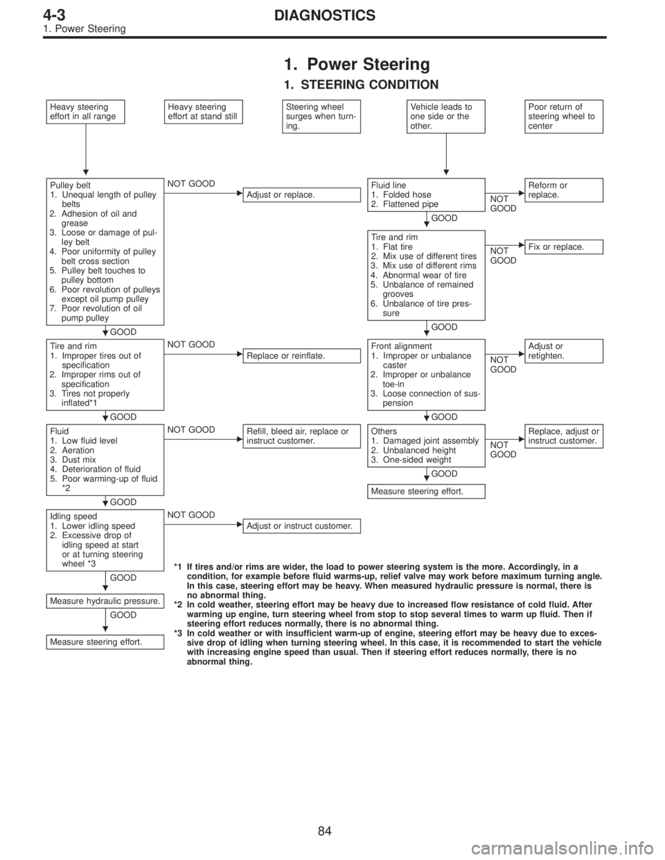
1. Power Steering
1. STEERING CONDITION
Heavy steering
effort in all rangeHeavy steering
effort at stand stillSteering wheel
surges when turn-
ing.Vehicle leads to
one side or the
other.Poor return of
steering wheel to
center
Pulley belt
1. Unequal length of pulley
belts
2. Adhesion of oil and
grease
3. Loose or damage of pul-
ley belt
4. Poor uniformity of pulley
belt cross section
5. Pulley belt touches to
pulley bottom
6. Poor revolution of pulleys
except oil pump pulley
7. Poor revolution of oil
pump pulley
GOOD
�NOT GOOD
Adjust or replace.Fluid line
1. Folded hose
2. Flattened pipe
GOOD
�NOT
GOODReform or
replace.
Tire and rim
1. Flat tire
2. Mix use of different tires
3. Mix use of different rims
4. Abnormal wear of tire
5. Unbalance of remained
grooves
6. Unbalance of tire pres-
sure
GOOD
�NOT
GOODFix or replace.
Tire and rim
1. Improper tires out of
specification
2. Improper rims out of
specification
3. Tires not properly
inflated*1
GOOD
�NOT GOOD
Replace or reinflate.Front alignment
1. Improper or unbalance
caster
2. Improper or unbalance
toe-in
3. Loose connection of sus-
pension
GOOD
�NOT
GOODAdjust or
retighten.
Fluid
1. Low fluid level
2. Aeration
3. Dust mix
4. Deterioration of fluid
5. Poor warming-up of fluid
*2
GOOD
�NOT GOOD
Refill, bleed air, replace or
instruct customer.Others
1. Damaged joint assembly
2. Unbalanced height
3. One-sided weight
GOOD
Measure steering effort.
�NOT
GOODReplace, adjust or
instruct customer.
Idling speed
1. Lower idling speed
2. Excessive drop of
idling speed at start
or at turning steering
wheel *3
GOOD
�NOT GOOD
Adjust or instruct customer.
*1 If tires and/or rims are wider, the load to power steering system is the more. Accordingly, in a
condition, for example before fluid warms-up, relief valve may work before maximum turning angle.
In this case, steering effort may be heavy. When measured hydraulic pressure is normal, there is
no abnormal thing.
*2 In cold weather, steering effort may be heavy due to increased flow resistance of cold fluid. After
warming up engine, turn steering wheel from stop to stop several times to warm up fluid. Then if
steering effort reduces normally, there is no abnormal thing.
*3 In cold weather or with insufficient warm-up of engine, steering effort may be heavy due to exces-
sive drop of idling when turning steering wheel. In this case, it is recommended to start the vehicle
with increasing engine speed than usual. Then if steering effort reduces normally, there is no
abnormal thing. Measure hydraulic pressure.
GOOD
Measure steering effort.
��
�
��
��
�
�
�
�
84
4-3DIAGNOSTICS
1. Power Steering