Page 1847 of 2248

O: AIRBAG WARNING LIGHT REMAINS OFF.
DIAGNOSIS:
�Fuse No. 15 is blown.
�Body harness circuit is open.
�Airbag warning light is faulty.
�Airbag main harness is faulty.
�Airbag control module is faulty.
1. Fuse No. 15 inspection
O.K.
�Not O.K.
Replace fuse No. 15.
2. Body harness inspection
O.K.
�Not O.K.
Repair body harness.
3. Airbag warning light module (in combination
meter) inspection
O.K.
�Not O.K.
Replace airbag warning light module.
4. Airbag main harness inspection
O.K.
�Not O.K.
Replace airbag main harness.
Replace airbag control module.
CAUTION:
Before performing diagnostics on airbag system, turn
ignition switch“OFF”, disconnect battery ground
terminal, and then wait at least 20 seconds.
G5M0460
1. FUSE No. 15 INSPECTION
1) Remove and visually check fuse No. 15.
2) If fuse is blown, replace it with a new one. After con-
necting battery cable and turning ignition switch“ON”,ifit
blows again, proceed to“2. BODY HARNESS INSPEC-
TION”.
2. BODY HARNESS INSPECTION
Turn ignition switch“ON”(engine off) to make sure other
warning lights (in combination meter) illuminate. If they do
not, check body harness.
�
�
�
�
38
5-5SUPPLEMENTAL RESTRAINT SYSTEM
5. Diagnostics Chart with Trouble Code
Page 1850 of 2248
![SUBARU LEGACY 1995 Service Repair Manual 1. SELECTION OF CHECK PARTS
1) Conduct on-board diagnostic and call up trouble codes
stored in memory. <Ref. to 5-5 [T4B0].>
2) Select trouble code required to check airbag compo-
nent parts from thos](/manual-img/17/57432/w960_57432-1849.png "SUBARU LEGACY 1995 Service Repair Manual 1. SELECTION OF CHECK PARTS
1) Conduct on-board diagnostic and call up trouble codes
stored in memory. <Ref. to 5-5 [T4B0].>
2) Select trouble code required to check airbag compo-
nent parts from thos")
1. SELECTION OF CHECK PARTS
1) Conduct on-board diagnostic and call up trouble codes
stored in memory.
2) Select trouble code required to check airbag compo-
nent parts from those listed in table and reproduce symp-
tom.
Trouble codes Check parts Refer to 5-5:
02�Front sensor (RH, LH)
�Airbag main harness
�Airbag module (Driver/Passenger)
�Roll connector
�Airbag control moduleW4A0
W5A0
W3A1—W3A2
W7A0
W6A0
03�Front sensor (RH, LH)
�Airbag control moduleW4A0
W6A0
04�Airbag module (Passenger)
�Airbag main harness
�Airbag control moduleW3A2
W5A0
W6A0
11�Fuse No. 8
�Airbag main harness
�Airbag control module
�Body harnessT5D3
W5A0
W6A0
—
12�Roll connector
�Airbag module (Driver)
�Airbag main harness
�Airbag control moduleW7A0
W3A1
W5A0
W6A0
13�Airbag module (Driver)
�Roll connector
�Airbag main harness
�Airbag control moduleW3A1
W7A0
W5A0
W6A0
21�Airbag control module W6A0
22�Airbag module (Passenger)
�Airbag main harness
�Airbag control moduleW3A2
W5A0
W6A0
23�Airbag main harness
�Roll connector
�Airbag module (Driver/Passenger)
�Front sensor (RH, LH)
�Airbag control moduleW5A0
W7A0
W3A1—W3A2
W4A0
W6A0
24�Airbag module (Driver)
�Roll connector
�Airbag main harness
�Airbag control moduleW3A1
W7A0
W5A0
W6A0
32�Airbag module (Passenger)
�Roll connector
�Airbag main harness
�Airbag control moduleW3A2
W7A0
W5A0
W6A0
41
5-5SUPPLEMENTAL RESTRAINT SYSTEM
5. Diagnostics Chart with Trouble Code
Page 1852 of 2248

Q: WARNING LIGHT INDICATES TROUBLE
CODE, THEN NORMAL CODE.
—FLASHING NORMAL CODE.—
DIAGNOSIS:
�Airbag connector is faulty.
�Fuse No. 16 is blown.
�Airbag main harness is faulty.
�Airbag control module is faulty.
�Body harness is faulty.
1. Airbag connectors appearance and vibration
inspection
O.K.
�Not O.K.
Replace faulty parts.
2. Showering inspection to body
O.K.
�Not O.K.
Replace faulty parts.
3. Fuse No. 16, airbag main harness, airbag
control module, body harness appearance and
vibration inspection
O.K.
�Not O.K.
Replace faulty parts.
4. Showering inspection to body
O.K.
�Not O.K.
Replace faulty parts.
5. Warning light illumination check
O.K.
�Not O.K.
Go to“T4E0”diagnostics procedure.
Clear memory.
CAUTION:
Before performing diagnostics on airbag system, turn
ignition switch“OFF”, disconnect battery ground
cable, and then wait at least 20 seconds.
1. AIRBAG CONNECTORS APPEARANCE AND
VIBRATION INSPECTION
1) Conduct appearance inspection on airbag connectors
(AB2 through AB8).
NOTE:
Check terminals, case and wiring harnesses for damage.
2) Conduct vibration inspection on airbag connectors (AB2
through AB8).
NOTE:
Gently shake each airbag connector.
�
�
�
�
�
43
5-5SUPPLEMENTAL RESTRAINT SYSTEM
5. Diagnostics Chart with Trouble Code
Page 1853 of 2248
 Spray water on vehicle body.
CAUTION:
Do not directly spray water on airbag components.
2) Check passenger compartment for traces of leaking.
NOTE:
If leaks")
G5M0461
2. SHOWERING INSPECTION TO BODY
1) Spray water on vehicle body.
CAUTION:
Do not directly spray water on airbag components.
2) Check passenger compartment for traces of leaking.
NOTE:
If leaks are noted, also check wiring harnesses as water
may leak along them and wet airbag connectors.
3. FUSE No. 16, AIRBAG MAIN HARNESS, AIRBAG
CONTROL MODULE, BODY HARNESS APPEARANCE
AND VIBRATION INSPECTION
1) Conduct appearance inspection on fuse No. 16
5-5 [T5L3].>, airbag main harness ,
airbag control module and body
harness.
NOTE:
Also check connectors, terminals, wiring harness and case
for damage.
2) Conduct vibration inspection on fuse No. 16, airbag
main harness, airbag control module and body harness.
NOTE:
Gently shake each part.
G5M0461
4. SHOWERING INSPECTION TO BODY
1) Spray water on vehicle body.
CAUTION:
Do not directly spray water on each part.
2) Check passenger compartment for traces of leaking.
NOTE:
If leaks are noted, check wiring harnesses as water may
leak along them and get parts wet.
5. WARNING LIGHT ILLUMINATION CHECK
Turn ignition switch“ON”(engine off) and observe airbag
warning light.
Airbag warning light comes“ON”for 8 seconds then goes
out and stays out.
44
5-5SUPPLEMENTAL RESTRAINT SYSTEM
5. Diagnostics Chart with Trouble Code
Page 1863 of 2248
 Connect select monitor.
2) Start the engine and turn cruise control main switch to
ON.
3) Set select monitor in“FB0”mode.
4) Drive vehicle at least 40 km/h")
2. CRUISE CANCEL CONDITIONS DIAGNOSIS
1) Connect select monitor.
2) Start the engine and turn cruise control main switch to
ON.
3) Set select monitor in“FB0”mode.
4) Drive vehicle at least 40 km/h (25 MPH) with cruise
speed set.
5) If cruise speed is canceled itself (without doing any
cancel operations), a trouble code will appear on select
monitor display.
CAUTION:
�A trouble code will also appear when cruise cancel
is effected by driver. Do not confuse.
�Have a co-worker ride in vehicle to assist in diagno-
sis during driving.
NOTE:
Trouble code will be cleared by turning ignition switch or
cruise control main switch to OFF.
3. REAL-TIME DIAGNOSIS
1) Connect select monitor.
2) Turn ignition switch and cruise control main switch to
ON.
3) Set select monitor in“FA 0”mode.
4) Ensure that normal indication is displayed when con-
trols are operated as indicated below:
�When SET/COAST switch is pressed.
�When RESUME/ACCEL switch is pressed.
�When brake pedal is depressed. (Stop and brake switch
turns ON.)
�When clutch pedal is depressed. (MT model)
�When select lever is set to N position. (AT model)
10
6-2BODY ELECTRICAL SYSTEM
6. Diagnostics Chart for On-board Diagnosis System
Page 1867 of 2248
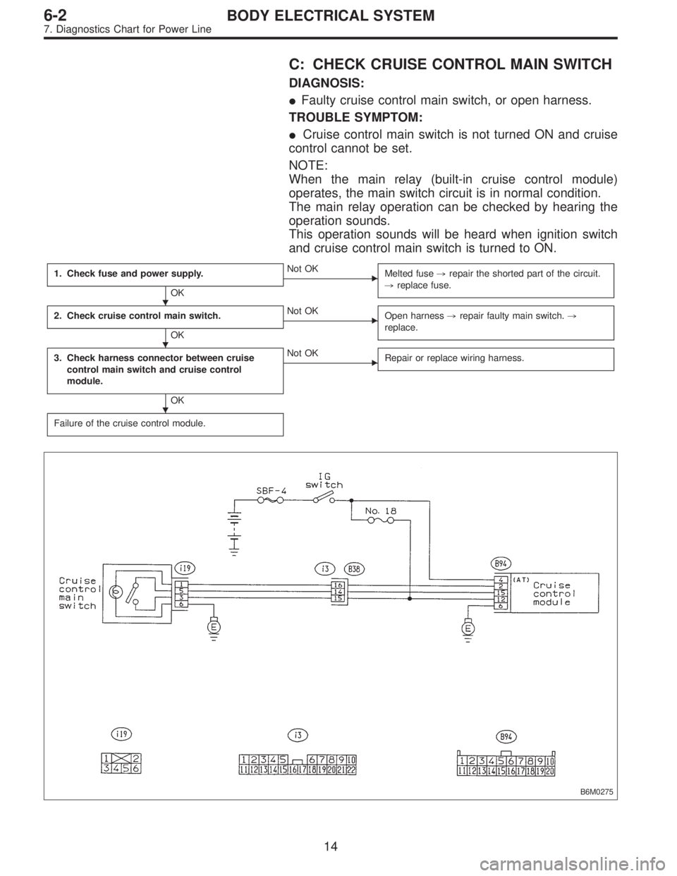
C: CHECK CRUISE CONTROL MAIN SWITCH
DIAGNOSIS:
�Faulty cruise control main switch, or open harness.
TROUBLE SYMPTOM:
�Cruise control main switch is not turned ON and cruise
control cannot be set.
NOTE:
When the main relay (built-in cruise control module)
operates, the main switch circuit is in normal condition.
The main relay operation can be checked by hearing the
operation sounds.
This operation sounds will be heard when ignition switch
and cruise control main switch is turned to ON.
1. Check fuse and power supply.
OK
�Not OK
Melted fuse,repair the shorted part of the circuit.
,replace fuse.
2. Check cruise control main switch.
OK
�Not OK
Open harness,repair faulty main switch.,
replace.
3. Check harness connector between cruise
control main switch and cruise control
module.
OK
�Not OK
Repair or replace wiring harness.
Failure of the cruise control module.
B6M0275
�
�
�
14
6-2BODY ELECTRICAL SYSTEM
7. Diagnostics Chart for Power Line
Page 1868 of 2248
 Check fuse No. 18.
2) Turn ignition switch to ON.
3) Measure voltage between fuse box connector and body.
Connector & terminal / Specified voltage:
(B51) No.")
G6M0181
1. CHECK FUSE AND POWER SUPPLY.
1) Check fuse No. 18.
2) Turn ignition switch to ON.
3) Measure voltage between fuse box connector and body.
Connector & terminal / Specified voltage:
(B51) No. 4—Body / 10 V, or more
B6M0183B
2. CHECK CRUISE CONTROL MAIN SWITCH.
1) Turn ignition switch to OFF.
2) Remove cruise control main switch and disconnect con-
nector.
3) Turn ignition switch to ON.
4) Measure voltage between cruise control main switch
connector and body.
Connector & terminal / Specified voltage:
(i19) No. 3—Body / 10 V, or more
G6M0244
5) Measure resistance between cruise control main switch
terminals.
Terminals / Specified resistance:
No. 3—No. 5 / 10Ω, max. (ON)
1MΩ, min. (OFF)
B6M0184B
3. CHECK HARNESS CONNECTOR BETWEEN
CRUISE CONTROL MAIN SWITCH AND CRUISE
CONTROL MODULE.
1) Connect connector.
2) Turn ignition switch to ON.
3) Turn cruise control main switch to ON.
4) Measure voltage between each terminal of cruise con-
trol main switch or cruise control module and body.
Connector & terminal / Specified voltage:
(i19) No. 3—Body / 10 V, or more
(i19) No. 5—Body / 10 V, or more
(B94) No. 15—Body / 10 V, or more
NOTE:
Depress cruise control main switch with fingers while mea-
suring (i19) No. 5—Body.
15
6-2BODY ELECTRICAL SYSTEM
7. Diagnostics Chart for Power Line
Page:
< prev 1-8 9-16 17-24