Page 1761 of 2248
B4M0733A
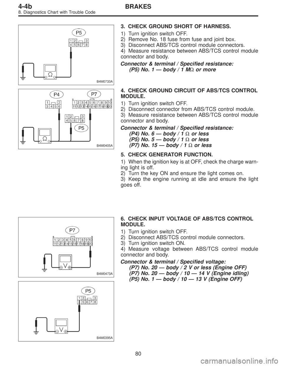
3. CHECK GROUND SHORT OF HARNESS.
1) Turn ignition switch OFF.
2) Remove No. 18 fuse from fuse and joint box.
3) Disconnect ABS/TCS control module connectors.
4) Measure resistance between ABS/TCS control module
connector and body.
Connector & terminal / Specified resistance:
(P5) No. 1—body/1MΩor more
B4M0405A
4. CHECK GROUND CIRCUIT OF ABS/TCS CONTROL
MODULE.
1) Turn ignition switch OFF.
2) Disconnect connector from ABS/TCS control module.
3) Measure resistance between ABS/TCS control module
connector and body.
Connector & terminal / Specified resistance:
(P4) No. 6—body / 1Ωor less
(P5) No. 5—body / 1Ωor less
(P7) No. 15—body / 1Ωor less
5. CHECK GENERATOR FUNCTION.
1) When the ignition key is at OFF, check the charge warn-
ing light is off.
2) Turn the key ON and ensure the light comes on.
3) Keep the engine running at idle and ensure the light
goes off.
B4M0473A
B4M0395A
6. CHECK INPUT VOLTAGE OF ABS/TCS CONTROL
MODULE.
1) Turn ignition switch OFF.
2) Disconnect ABS/TCS control module connectors.
3) Turn ignition switch ON.
4) Measure voltage between ABS/TCS control module
connector and body.
Connector & terminal / Specified voltage:
(P7) No. 20—body/2Vorless (Engine OFF)
(P7) No. 20—body / 10—14 V (Engine idling)
(P5) No. 1—body / 10—13 V (Engine OFF)
80
4-4bBRAKES
8. Diagnostics Chart with Trouble Code
Page 1804 of 2248
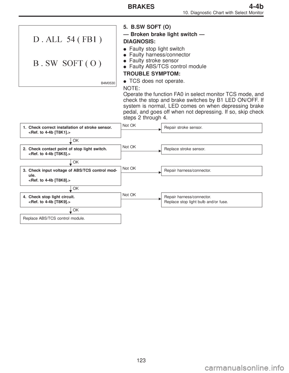
B4M0530
5. B.SW SOFT (O)
—Broken brake light switch—
DIAGNOSIS:
�Faulty stop light switch
�Faulty harness/connector
�Faulty stroke sensor
�Faulty ABS/TCS control module
TROUBLE SYMPTOM:
�TCS does not operate.
NOTE:
Operate the function FA0 in select monitor TCS mode, and
check the stop and brake switches by B1 LED ON/OFF. If
system is normal, LED comes on when depressing brake
pedal, and goes off when not depressing. If so, skip check
steps 2 through 4.
1. Check correct installation of stroke sensor.
OK
�Not OK
Repair stroke sensor.
2. Check contact point of stop light switch.
OK
�Not OK
Replace stroke sensor.
3. Check input voltage of ABS/TCS control mod-
ule.
OK
�Not OK
Repair harness/connector.
4. Check stop light circuit.
OK
�Not OK
Repair harness/connector.
Replace stop light bulb and/or fuse.
Replace ABS/TCS control module.
�
�
�
�
123
4-4bBRAKES
10. Diagnostic Chart with Select Monitor
Page 1819 of 2248
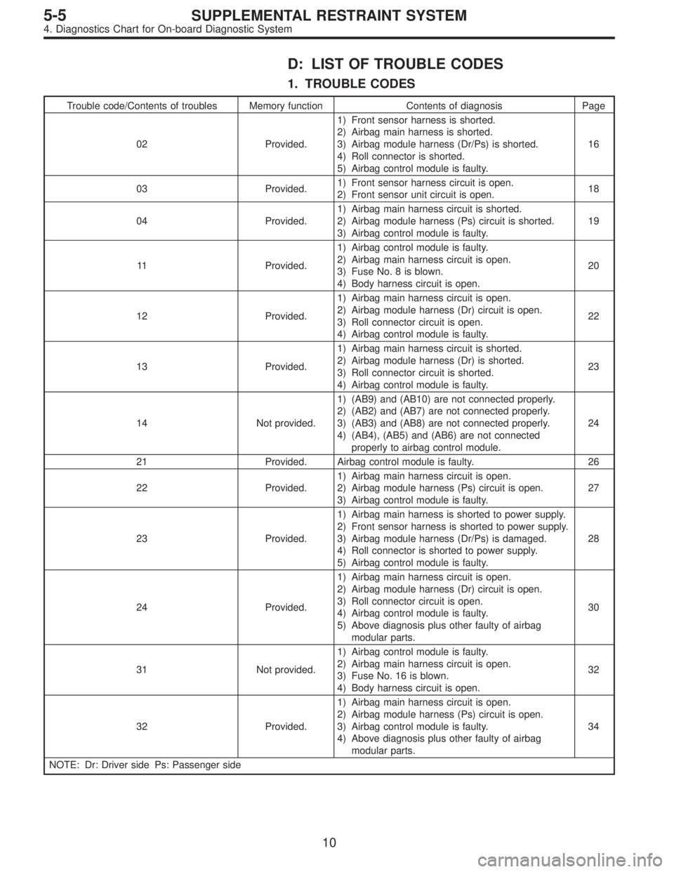
D: LIST OF TROUBLE CODES
1. TROUBLE CODES
Trouble code/Contents of troubles Memory function Contents of diagnosis Page
02 Provided.1) Front sensor harness is shorted.
2) Airbag main harness is shorted.
3) Airbag module harness (Dr/Ps) is shorted.
4) Roll connector is shorted.
5) Airbag control module is faulty.16
03 Provided.1) Front sensor harness circuit is open.
2) Front sensor unit circuit is open.18
04 Provided.1) Airbag main harness circuit is shorted.
2) Airbag module harness (Ps) circuit is shorted.
3) Airbag control module is faulty.19
11 Provided.1) Airbag control module is faulty.
2) Airbag main harness circuit is open.
3) Fuse No. 8 is blown.
4) Body harness circuit is open.20
12 Provided.1) Airbag main harness circuit is open.
2) Airbag module harness (Dr) circuit is open.
3) Roll connector circuit is open.
4) Airbag control module is faulty.22
13 Provided.1) Airbag main harness circuit is shorted.
2) Airbag module harness (Dr) is shorted.
3) Roll connector circuit is shorted.
4) Airbag control module is faulty.23
14 Not provided.1) (AB9) and (AB10) are not connected properly.
2) (AB2) and (AB7) are not connected properly.
3) (AB3) and (AB8) are not connected properly.
4) (AB4), (AB5) and (AB6) are not connected
properly to airbag control module.24
21 Provided. Airbag control module is faulty. 26
22 Provided.1) Airbag main harness circuit is open.
2) Airbag module harness (Ps) circuit is open.
3) Airbag control module is faulty.27
23 Provided.1) Airbag main harness is shorted to power supply.
2) Front sensor harness is shorted to power supply.
3) Airbag module harness (Dr/Ps) is damaged.
4) Roll connector is shorted to power supply.
5) Airbag control module is faulty.28
24 Provided.1) Airbag main harness circuit is open.
2) Airbag module harness (Dr) circuit is open.
3) Roll connector circuit is open.
4) Airbag control module is faulty.
5) Above diagnosis plus other faulty of airbag
modular parts.30
31 Not provided.1) Airbag control module is faulty.
2) Airbag main harness circuit is open.
3) Fuse No. 16 is blown.
4) Body harness circuit is open.32
32 Provided.1) Airbag main harness circuit is open.
2) Airbag module harness (Ps) circuit is open.
3) Airbag control module is faulty.
4) Above diagnosis plus other faulty of airbag
modular parts.34
NOTE: Dr: Driver side Ps: Passenger side
10
5-5SUPPLEMENTAL RESTRAINT SYSTEM
4. Diagnostics Chart for On-board Diagnostic System
Page 1820 of 2248
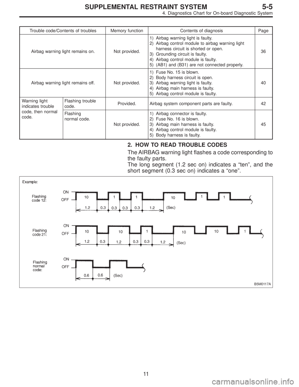
Trouble code/Contents of troubles Memory function Contents of diagnosis Page
Airbag warning light remains on. Not provided.1) Airbag warning light is faulty.
2) Airbag control module to airbag warning light
harness circuit is shorted or open.
3) Grounding circuit is faulty.
4) Airbag control module is faulty.
5) (AB1) and (B31) are not connected properly.36
Airbag warning light remains off. Not provided.1) Fuse No. 15 is blown.
2) Body harness circuit is open.
3) Airbag warning light is faulty.
4) Airbag main harness is faulty.
5) Airbag control module is faulty.40
Warning light
indicates trouble
code, then normal
code.Flashing trouble
code.Provided. Airbag system component parts are faulty. 42
Flashing
normal code.
Not provided.1) Airbag connector is faulty.
2) Fuse No. 16 is blown.
3) Airbag main harness is faulty.
4) Airbag control module is faulty.
5) Body harness is faulty.45
2. HOW TO READ TROUBLE CODES
The AIRBAG warning light flashes a code corresponding to
the faulty parts.
The long segment (1.2 sec on) indicates a“ten”, and the
short segment (0.3 sec on) indicates a“one”.
B5M0117A
11
5-5SUPPLEMENTAL RESTRAINT SYSTEM
4. Diagnostics Chart for On-board Diagnostic System
Page 1828 of 2248
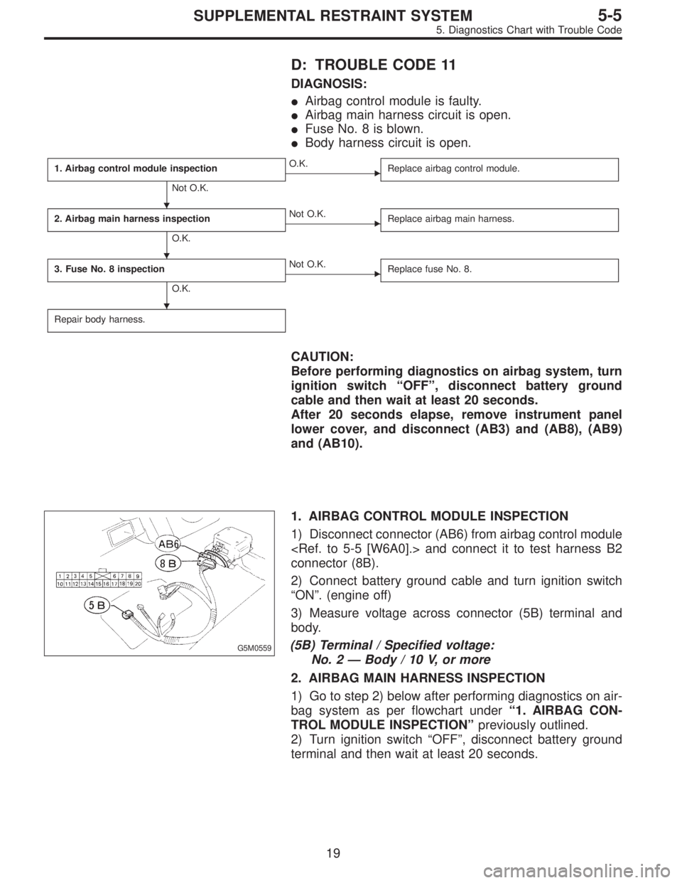
D: TROUBLE CODE 11
DIAGNOSIS:
�Airbag control module is faulty.
�Airbag main harness circuit is open.
�Fuse No. 8 is blown.
�Body harness circuit is open.
1. Airbag control module inspection
Not O.K.
�O.K.
Replace airbag control module.
2. Airbag main harness inspection
O.K.
�Not O.K.
Replace airbag main harness.
3. Fuse No. 8 inspection
O.K.
�Not O.K.
Replace fuse No. 8.
Repair body harness.
CAUTION:
Before performing diagnostics on airbag system, turn
ignition switch“OFF”, disconnect battery ground
cable and then wait at least 20 seconds.
After 20 seconds elapse, remove instrument panel
lower cover, and disconnect (AB3) and (AB8), (AB9)
and (AB10).
G5M0559
1. AIRBAG CONTROL MODULE INSPECTION
1) Disconnect connector (AB6) from airbag control module
and connect it to test harness B2
connector (8B).
2) Connect battery ground cable and turn ignition switch
“ON”. (engine off)
3) Measure voltage across connector (5B) terminal and
body.
(5B) Terminal / Specified voltage:
No. 2—Body / 10 V, or more
2. AIRBAG MAIN HARNESS INSPECTION
1) Go to step 2) below after performing diagnostics on air-
bag system as per flowchart under“1. AIRBAG CON-
TROL MODULE INSPECTION”previously outlined.
2) Turn ignition switch“OFF”, disconnect battery ground
terminal and then wait at least 20 seconds.
�
�
�
19
5-5SUPPLEMENTAL RESTRAINT SYSTEM
5. Diagnostics Chart with Trouble Code
Page 1829 of 2248
B5M0119B
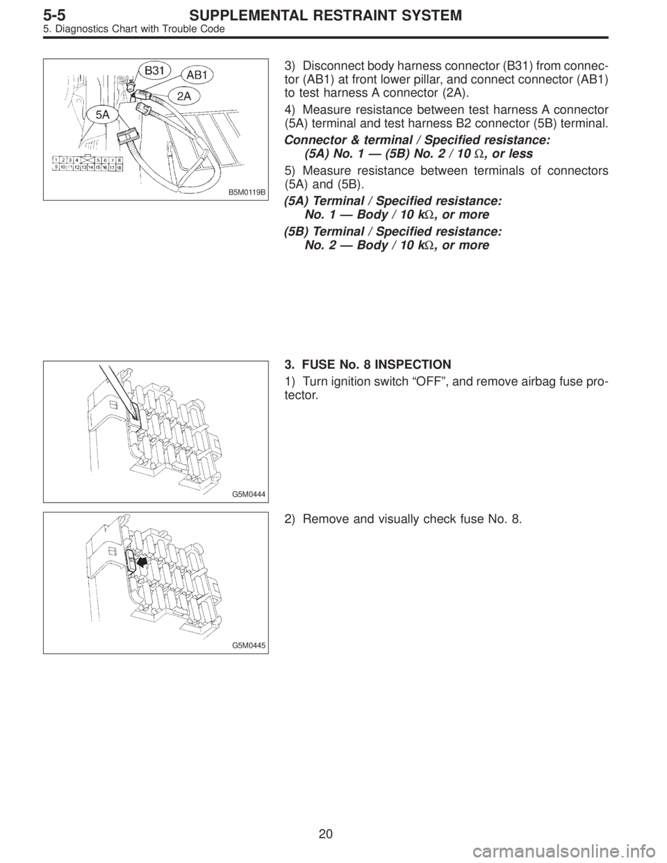
3) Disconnect body harness connector (B31) from connec-
tor (AB1) at front lower pillar, and connect connector (AB1)
to test harness A connector (2A).
4) Measure resistance between test harness A connector
(5A) terminal and test harness B2 connector (5B) terminal.
Connector & terminal / Specified resistance:
(5A) No. 1—(5B) No.2/10Ω, or less
5) Measure resistance between terminals of connectors
(5A) and (5B).
(5A) Terminal / Specified resistance:
No. 1—Body/10kΩ, or more
(5B) Terminal / Specified resistance:
No. 2—Body/10kΩ, or more
G5M0444
3. FUSE No. 8 INSPECTION
1) Turn ignition switch“OFF”, and remove airbag fuse pro-
tector.
G5M0445
2) Remove and visually check fuse No. 8.
20
5-5SUPPLEMENTAL RESTRAINT SYSTEM
5. Diagnostics Chart with Trouble Code
Page 1840 of 2248
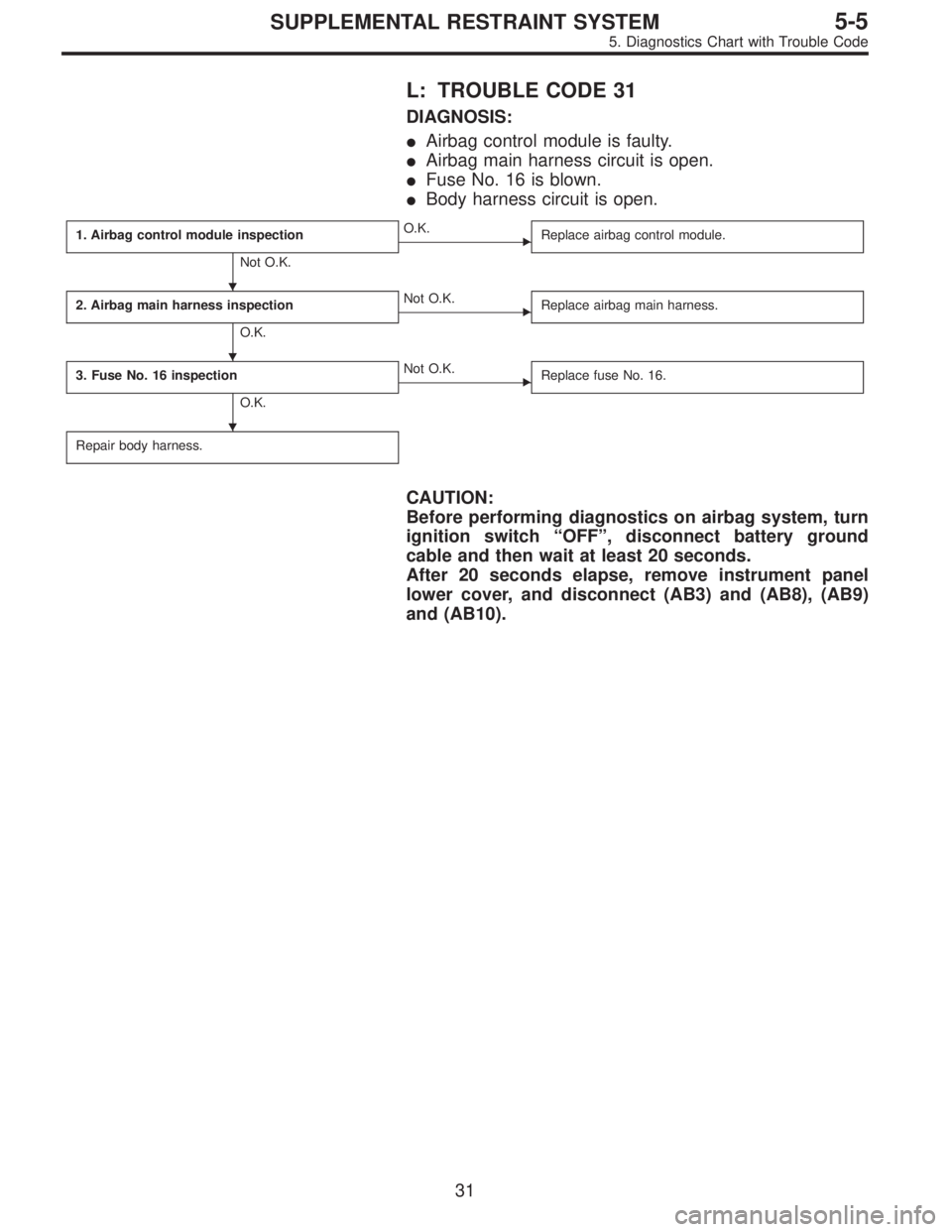
L: TROUBLE CODE 31
DIAGNOSIS:
�Airbag control module is faulty.
�Airbag main harness circuit is open.
�Fuse No. 16 is blown.
�Body harness circuit is open.
1. Airbag control module inspection
Not O.K.
�O.K.
Replace airbag control module.
2. Airbag main harness inspection
O.K.
�Not O.K.
Replace airbag main harness.
3. Fuse No. 16 inspection
O.K.
�Not O.K.
Replace fuse No. 16.
Repair body harness.
CAUTION:
Before performing diagnostics on airbag system, turn
ignition switch“OFF”, disconnect battery ground
cable and then wait at least 20 seconds.
After 20 seconds elapse, remove instrument panel
lower cover, and disconnect (AB3) and (AB8), (AB9)
and (AB10).
�
�
�
31
5-5SUPPLEMENTAL RESTRAINT SYSTEM
5. Diagnostics Chart with Trouble Code
Page 1841 of 2248
![SUBARU LEGACY 1995 Service Repair Manual G5M0559
1. AIRBAG CONTROL MODULE INSPECTION
1) Disconnect connector (AB6) from airbag control module
<Ref. to 5-5 [W6A0].>, and connect it to test harness B2
connector (8B).
2) Connect battery ground](/manual-img/17/57432/w960_57432-1840.png "SUBARU LEGACY 1995 Service Repair Manual G5M0559
1. AIRBAG CONTROL MODULE INSPECTION
1) Disconnect connector (AB6) from airbag control module
<Ref. to 5-5 [W6A0].>, and connect it to test harness B2
connector (8B).
2) Connect battery ground")
G5M0559
1. AIRBAG CONTROL MODULE INSPECTION
1) Disconnect connector (AB6) from airbag control module
, and connect it to test harness B2
connector (8B).
2) Connect battery ground cable and turn ignition switch
“ON”(engine off).
3) Measure voltage across connector (5B) terminal and
body.
(5B) Terminal / Specified voltage:
No. 5—Body / 10 V, or more
2. AIRBAG MAIN HARNESS INSPECTION
1) Go to step 2) below after performing diagnostics on air-
bag system as per flowchart under“1. AIRBAG CON-
TROL MODULE INSPECTION”previously outlined.
2) Turn ignition switch“OFF”, disconnect battery ground
cable and then wait at least 20 seconds.
B5M0119B
3) Disconnect connector (AB1) from body harness con-
nector (B31) at front lower pillar, and connect connector
(AB1) to test harness A connector (2A).
4) Measure resistance between test harness A connector
(5A) and test harness B2 connector (5B) terminals.
Connector & terminal / Specified resistance:
(5A) No. 9—(5B) No.5/10Ω, or less
5) Measure resistance between each terminal of connec-
tors (5A) and (5B) and body.
(5A) Terminal / Specified resistance:
No. 9—Body/10kΩ, or more
(5B) Terminal / Specified resistance:
No. 5—Body/10kΩ, or more
G5M0453
3. FUSE No. 16 INSPECTION
Make sure ignition switch is turned“OFF”, then remove and
visually check fuse No. 16.
32
5-5SUPPLEMENTAL RESTRAINT SYSTEM
5. Diagnostics Chart with Trouble Code