Page 907 of 2248

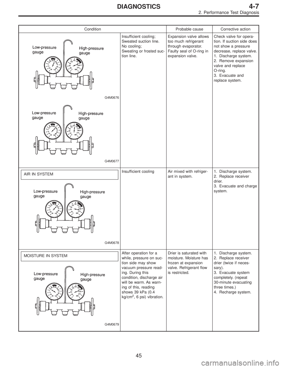
Condition Probable cause Corrective action
G4M0676
G4M0677
Insufficient cooling;
Sweated suction line.
No cooling;
Sweating or frosted suc-
tion line.Expansion valve allows
too much refrigerant
through evaporator.
Faulty seal of O-ring in
expansion valve.Check valve for opera-
tion. If suction side does
not show a pressure
decrease, replace valve.
1. Discharge system.
2. Remove expansion
valve and replace
O-ring.
3. Evacuate and
replace system.
AIR IN SYSTEM
G4M0678
Insufficient cooling Air mixed with refriger-
ant in system.1. Discharge system.
2. Replace receiver
drier.
3. Evacuate and charge
system.
MOISTURE IN SYSTEM
G4M0679
After operation for a
while, pressure on suc-
tion side may show
vacuum pressure read-
ing. During this
condition, discharge air
will be warm. As warn-
ing of this, reading
shows 39 kPa (0.4
kg/cm
2, 6 psi) vibration.Drier is saturated with
moisture. Moisture has
frozen at expansion
valve. Refrigerant flow
is restricted.1. Discharge system.
2. Replace receiver
drier (twice if neces-
sary).
3. Evacuate system
completely. (repeat
30-minute evacuating
three times.)
4. Recharge system.
45
4-7DIAGNOSTICS
2. Performance Test Diagnosis
Page 908 of 2248

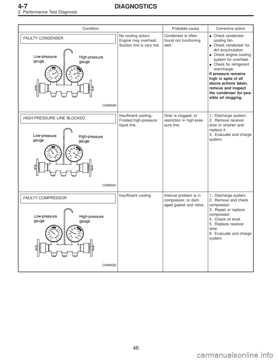
Condition Probable cause Corrective action
FAULTY CONDENSER
G4M0680
No cooling action;
Engine may overheat.
Suction line is very hot.Condenser is often
found not functioning
well.�Check condenser
cooling fan.
�Check condenser for
dirt accumulation.
�Check engine cooling
system for overheat.
�Check for refrigerant
overcharge.
If pressure remains
high in spite of all
above actions taken,
remove and inspect
the condenser for pos-
sible oil clogging.
HIGH-PRESSURE LINE BLOCKED
G4M0681
Insufficient cooling;
Frosted high-pressure
liquid line.Drier is clogged, or
restriction in high-pres-
sure line.1. Discharge system.
2. Remove receiver
drier or strainer and
replace it.
3. Evacuate and charge
system.
FAULTY COMPRESSOR
G4M0682
Insufficient cooling Internal problem is in
compressor, or dam-
aged gasket and valve.1. Discharge system.
2. Remove and check
compressor.
3. Repair or replace
compressor.
4. Check oil level.
5. Replace receiver
drier.
6. Evacuate and charge
system.
46
4-7DIAGNOSTICS
2. Performance Test Diagnosis
Page 1084 of 2248
B6M0482
8) Remove bolts which secure IC regulator, diode and
brush holder.
CAUTION:
Do not apply a shock or load to IC regulator cooling
fins.
G6M0075
C: INSPECTION AND REPAIR
1. ROTOR
1) Slip ring surface
Inspect slip rings for contamination or any roughness of the
sliding surface.
Clean or polish with #500 to #600 emery paper if defective.
B6M0483A
2) Slip ring outside diameter
Measure slip ring outside diameter. If slip ring is worn,
replace rotor.
Slip ring outside diameter:
Standard
27 mm (1.06 in)
Limit
26 mm (1.02 in)
B6M0484A
3) Continuity test
Check continuity between slip rings. If continuity does not
exist, replace rotor.
B6M0485A
4) Insulation test
Check continuity between slip ring and rotor core or shaft.
If continuity exists, replace rotor.
18
6-1SERVICE PROCEDURE
2. Generator
Page 1308 of 2248
2. CHECK LIST FOR INTERVIEW
Check the following items when problem occurred.
Customer’s name Engine no.
Date of sale Fuel brand
Date of repair Odometer readingkm
miles
Vin no.
Weather�Fine�Cloudy�Rainy�Snowy�Various/Other
Outdoor Temperature�Hot�Warm�Cool�Cold (approx.°F/°C)
Place�Highway�Suburbs�Inner City�Uphill�Downhill
�Rough road�Other
Engine Temp.�Cold�Warming-up�After warming-up�Any temp.�Other
Engine speed
0 2,000 4,000 6,000 8,000 rpm
Driving conditions�Not affected
�At starting�While idling�At racing
�While accelerating�While cruising
�While decelerating�While turning (RH/LH)
Vehicle speed
0 10203040 5060MPH
Headlight�ON /�OFF
Blower�ON /�OFF
A/C compressor�ON /�OFF
Cooling fan�ON /�OFF
Front wiper�ON /�OFF
Rear wiper�ON /�OFF
Rear defogger�ON /�OFF
Radio�ON /�OFF
CD/Cassette�ON /�OFF
Car phone�ON /�OFF
CB
NOTE: Use copies of this page for interviewing customers.
102
2-7ON-BOARD DIAGNOSTICS II SYSTEM
7. Basic Diagnostics Procedure
Page 1410 of 2248

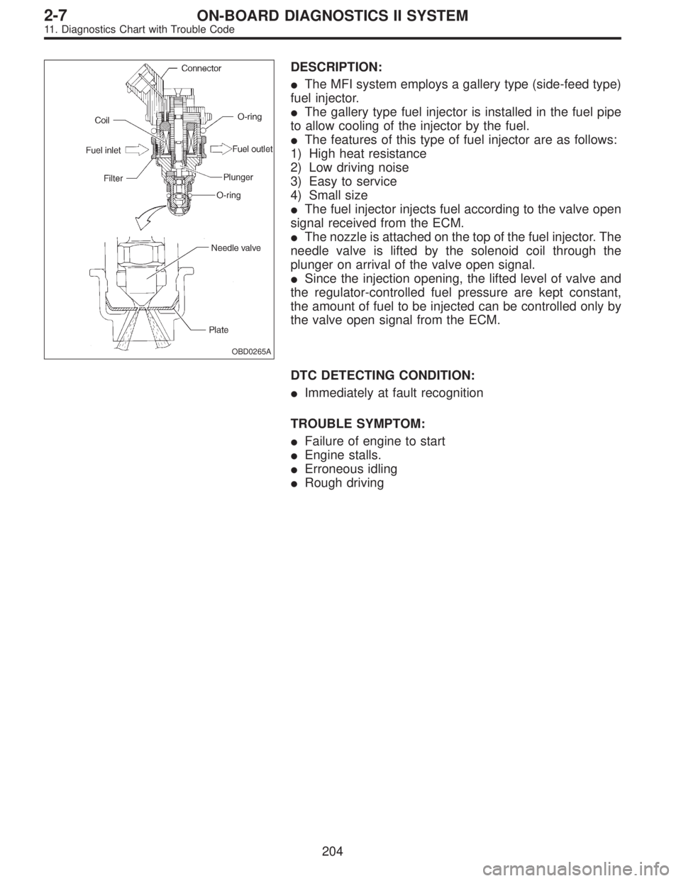
OBD0265A
DESCRIPTION:
�The MFI system employs a gallery type (side-feed type)
fuel injector.
�The gallery type fuel injector is installed in the fuel pipe
to allow cooling of the injector by the fuel.
�The features of this type of fuel injector are as follows:
1) High heat resistance
2) Low driving noise
3) Easy to service
4) Small size
�The fuel injector injects fuel according to the valve open
signal received from the ECM.
�The nozzle is attached on the top of the fuel injector. The
needle valve is lifted by the solenoid coil through the
plunger on arrival of the valve open signal.
�Since the injection opening, the lifted level of valve and
the regulator-controlled fuel pressure are kept constant,
the amount of fuel to be injected can be controlled only by
the valve open signal from the ECM.
DTC DETECTING CONDITION:
�Immediately at fault recognition
TROUBLE SYMPTOM:
�Failure of engine to start
�Engine stalls.
�Erroneous idling
�Rough driving
204
2-7ON-BOARD DIAGNOSTICS II SYSTEM
11. Diagnostics Chart with Trouble Code
Page 1537 of 2248

OBD0527
BI: DTC P1500
—RADIATOR FAN RELAY 1 CIRCUIT
MALFUNCTION (FAN
—1)—
DESCRIPTION:
�The engine cooling system consists of a down-flow
radiator which features high heat-dissipation performance,
an electric motor fan, an engine coolant pump, a
thermostat, and an engine coolant temperature sensor.
�The ON-OFF control of the radiator fan is governed by
the ECM which receives signals sent from the engine cool-
ant temperature sensor. On models which are equipped
with an air conditioning system, the ECM receives signals
sent from the engine coolant temperature sensor, vehicle
speed sensor 2 and A/C switch. These signals simulta-
neously turn ON or OFF the radiator main fan and radiator
sub fan as well as setting them at“HI”or“LO”speed.
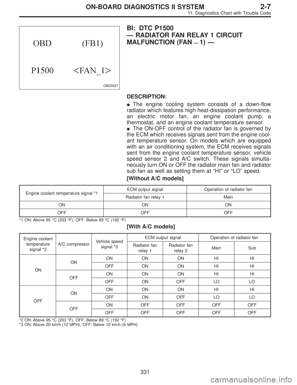
[Without A/C models]
Engine coolant temperature signal *1ECM output signal Operation of radiator fan
Radiator fan relay 1 Main
ON ON ON
OFF OFF OFF
*1 ON: Above 95°C (203°F), OFF: Below 89°C (192°F)
[With A/C models]
Engine coolant
temperature
signal *2A/C compressorVehicle speed
signal *3ECM output signal Operation of radiator fan
Radiator fan
relay 1Radiator fan
relay 2Main Sub
ONONON ON ON HI HI
OFF ON ON HI HI
OFFON ON ON HI HI
OFF ON OFF LO LO
OFFONON ON ON HI HI
OFF ON OFF LO LO
OFFON OFF OFF OFF OFF
OFF OFF OFF OFF OFF
*2 ON: Above 95°C (203°F), OFF: Below 89°C (192°F)
*3 ON: Above 20 km/h (12 MPH), OFF: Below 10 km/h (6 MPH)
331
2-7ON-BOARD DIAGNOSTICS II SYSTEM
11. Diagnostics Chart with Trouble Code
Page 1546 of 2248
WIRING DIAGRAM:
�RHD model
B2M0461
When DTC P1104 is on display, check engine cooling sys-
tem.
CAUTION:
After repair or replacement of faulty parts, conduct
CLEAR MEMORY and INSPECTION MODES.
[T3D0] and [T3E0].>
NOTE:
If the vehicle, with the engine idling, is placed very close to
a wall or another vehicle, preventing normal cooling
function, the OBD system may detect malfunction.
340
2-7ON-BOARD DIAGNOSTICS II SYSTEM
11. Diagnostics Chart with Trouble Code
Page:
< prev 1-8 9-16 17-24