Page 257 of 2248
G2M0270
14) Install A/C pressure hoses. (With A/C)
CAUTION:
Use new O-rings.
Tightening torque:
25±7 N⋅m (2.5±0.7 kg-m, 18.1±5.1 ft-lb)
B2M0307A
15) Install cooling system.
(1) Attach radiator mounting cushions to body.
G2M0220
(2) Install radiator while fitting radiator pins to cush-
ions.
B2M0320
(3) Install radiator brackets and tighten bolts.
Tightening torque:
13.7±1.5 N⋅m (1.4±0.15 kg-m, 10.1±1.1 ft-lb)
G2M0263
(4) Connect radiator fan motor connector.
23
2-11SERVICE PROCEDURE
2. Engine
Page 347 of 2248

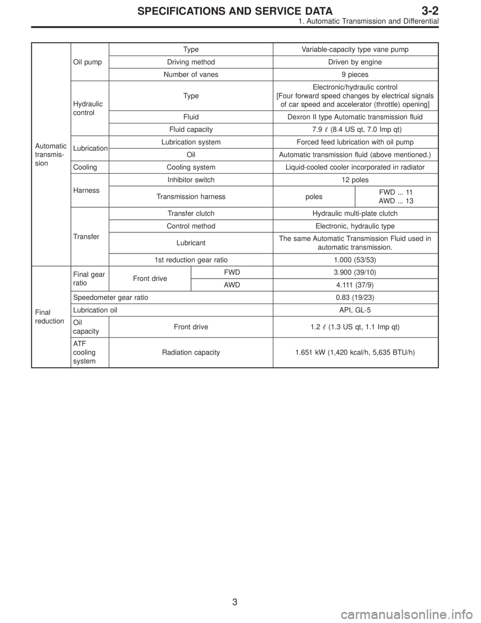
Automatic
transmis-
sionOil pumpType Variable-capacity type vane pump
Driving method Driven by engine
Number of vanes 9 pieces
Hydraulic
controlTypeElectronic/hydraulic control
[Four forward speed changes by electrical signals
of car speed and accelerator (throttle) opening]
Fluid Dexron II type Automatic transmission fluid
Fluid capacity 7.9�(8.4 US qt, 7.0 Imp qt)
LubricationLubrication system Forced feed lubrication with oil pump
Oil Automatic transmission fluid (above mentioned.)
Cooling Cooling system Liquid-cooled cooler incorporated in radiator
HarnessInhibitor switch 12 poles
Transmission harness polesFWD ... 11
AWD ... 13
TransferTransfer clutch Hydraulic multi-plate clutch
Control method Electronic, hydraulic type
LubricantThe same Automatic Transmission Fluid used in
automatic transmission.
1st reduction gear ratio 1.000 (53/53)
Final
reductionFinal gear
ratioFront driveFWD 3.900 (39/10)
AWD 4.111 (37/9)
Speedometer gear ratio 0.83 (19/23)
Lubrication oil API, GL-5
Oil
capacityFront drive 1.2�(1.3 US qt, 1.1 Imp qt)
AT F
cooling
systemRadiation capacity 1.651 kW (1,420 kcal/h, 5,635 BTU/h)
3
3-2SPECIFICATIONS AND SERVICE DATA
1. Automatic Transmission and Differential
Page 714 of 2248
7. CLEARANCE TABLE (LHD MODEL)
CAUTION:
This table lists various clearances that must be cor-
rectly adjusted to ensure normal vehicle driving with-
out interfering noise, or any other faults.
LocationMinimum
allowance
mm (in)LocationMinimum
allowance
mm (in)
�
1Crossmember—Pipe5 (0.20)�6Exhaust pipe—Pipe15 (0.59)
�
2DOJ—Shaft or joint14 (0.55)�7Exhaust pipe—Gearbox bolt15 (0.59)
�
3DOJ—Valve housing11 (0.43)�8Side frame—Hose A and B15 (0.59)
�
4Pipe—Pipe
2 (0.08)�
9Cruise control pump—Hose A and B15 (0.59)
Pipe—Crossmember�
10Pipe portion of hose A—Pipe portion of hose B1.5
(0.059)
�
5Stabilizer—Pipe5 (0.20)�11AT cooling hose—Joint20 (0.79)
B4M0565A
98
4-3DIAGNOSTICS
1. Power Steering
Page 862 of 2248

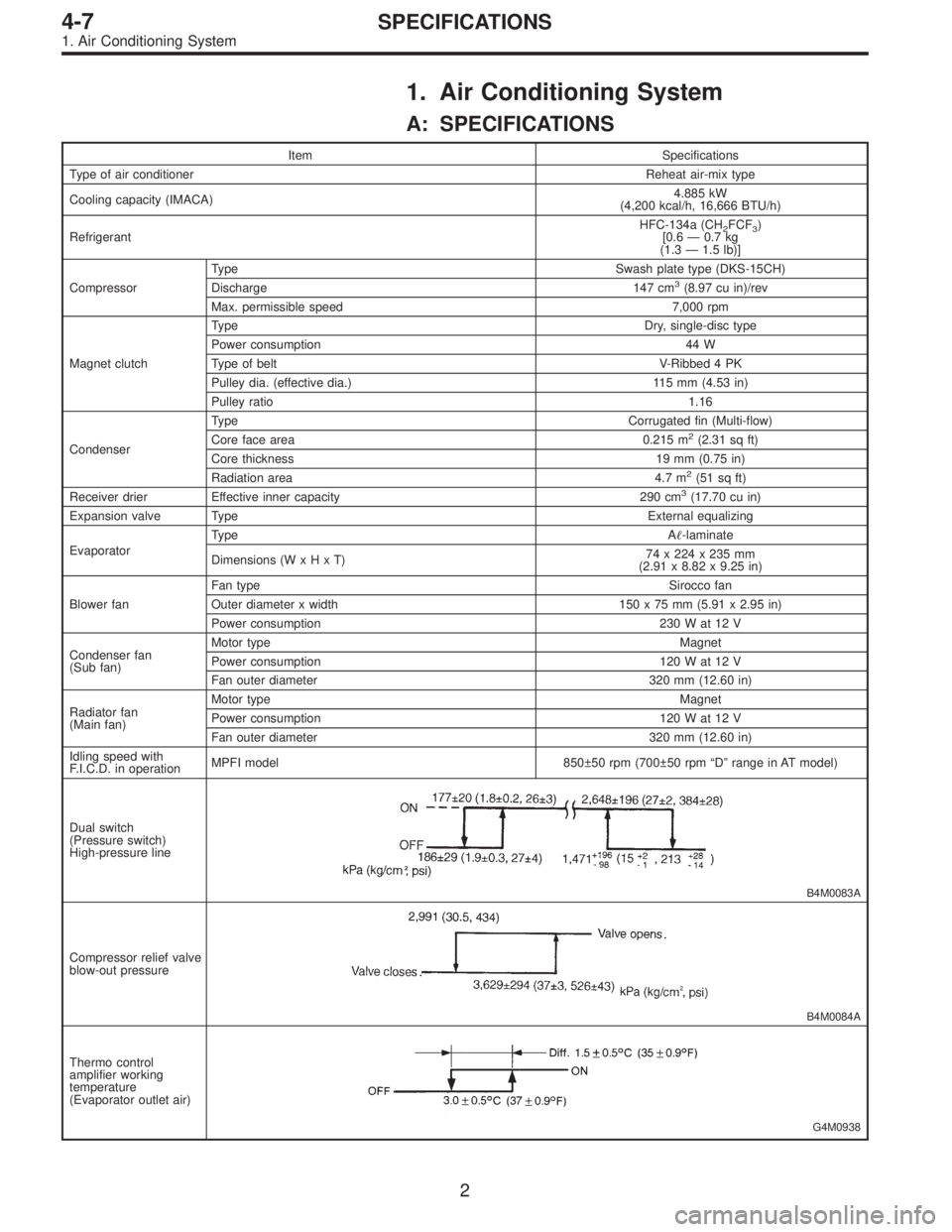
1. Air Conditioning System
A: SPECIFICATIONS
Item Specifications
Type of air conditionerReheat air-mix type
Cooling capacity (IMACA)4.885 kW
(4,200 kcal/h, 16,666 BTU/h)
RefrigerantHFC-134a (CH
2FCF3)
[0.6 — 0.7 kg
(1.3 — 1.5 lb)]
CompressorType Swash plate type (DKS-15CH)
Discharge 147 cm
3(8.97 cu in)/rev
Max. permissible speed 7,000 rpm
Magnet clutchTy p eDry, single-disc type
Power consumption 44 W
Type of belt V-Ribbed 4 PK
Pulley dia. (effective dia.) 115 mm (4.53 in)
Pulley ratio1.16
CondenserType Corrugated fin (Multi-flow)
Core face area 0.215 m
2(2.31 sq ft)
Core thickness 19 mm (0.75 in)
Radiation area 4.7 m
2(51 sq ft)
Receiver drier Effective inner capacity 290 cm3(17.70 cu in)
Expansion valve TypeExternal equalizing
EvaporatorTy p eA�-laminate
Dimensions (W x H x T)74 x 224 x 235 mm
(2.91 x 8.82 x 9.25 in)
Blower fanFan typeSirocco fan
Outer diameter x width 150 x 75 mm (5.91 x 2.95 in)
Power consumption 230 W at 12 V
Condenser fan
(Sub fan)Motor typeMagnet
Power consumption 120 W at 12 V
Fan outer diameter 320 mm (12.60 in)
Radiator fan
(Main fan)Motor typeMagnet
Power consumption 120 W at 12 V
Fan outer diameter 320 mm (12.60 in)
Idling speed with
F.I.C.D. in operationMPFI model 850±50 rpm (700±50 rpm “D” range in AT model)
Dual switch
(Pressure switch)
High-pressure line
B4M0083A
Compressor relief valve
blow-out pressure
B4M0084A
Thermo control
amplifier working
temperature
(Evaporator outlet air)
G4M0938
2
4-7SPECIFICATIONS
1. Air Conditioning System
Page 865 of 2248
2. Evaporator Module
1. LHD MODEL
B4M0086A
�1Thermo control amplifier
�
2Case upper
�
3Cooling module
�
4Pipe
�
5Seat
�
6Expansion valve
�
7Drain hose
�
8Case lower
�
9Resistor
�
10Resistor bracket
Tightening torque: N⋅m (kg-m, ft-lb)
T1: 7.4±2.0 (0.75±0.2, 5.4±1.4)
T2: 10±3 (1.0±0.3, 7.2±2.2)
T3: 15±5 (1.5±0.5, 10.8±3.6)
T4: 20±5 (2.0±0.5, 14.5±3.6)
5
4-7COMPONENT PARTS
2. Evaporator Module
Page 866 of 2248
2. RHD MODEL
B4M0684A
�1Thermo control amplifier
�
2Case upper
�
3Cooling module
�
4Pipe
�
5Expansion valve
�
6Drain hose
�
7Case lower
�
8Resistor
6
4-7COMPONENT PARTS
2. Evaporator Module
Page 869 of 2248

1. Safety Precautions
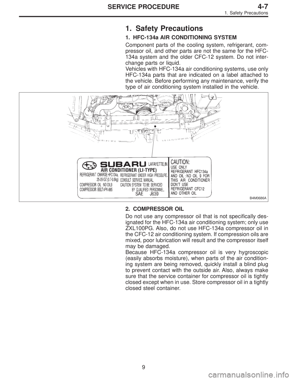
1. HFC-134a AIR CONDITIONING SYSTEM
Component parts of the cooling system, refrigerant, com-
pressor oil, and other parts are not the same for the HFC-
134a system and the older CFC-12 system. Do not inter-
change parts or liquid.
Vehicles with HFC-134a air conditioning systems, use only
HFC-134a parts that are indicated on a label attached to
the vehicle. Before performing any maintenance, verify the
type of air conditioning system installed in the vehicle.
B4M0686A
2. COMPRESSOR OIL
Do not use any compressor oil that is not specifically des-
ignated for the HFC-134a air conditioning system; only use
ZXL100PG. Also, do not use HFC-134a compressor oil in
the CFC-12 air conditioning system. If compression oils are
mixed, poor lubrication will result and the compressor itself
may be damaged.
Because HFC-134a compressor oil is very hygroscopic
(easily absorbs moisture), when parts of the air condition-
ing system are being removed, quickly install a blind plug
to prevent contact with the outside air. Also, always make
sure that the service container for compressor oil is tightly
closed except when in use. Store compressor oil in a tightly
closed steel container.
9
4-7SERVICE PROCEDURE
1. Safety Precautions
Page 906 of 2248

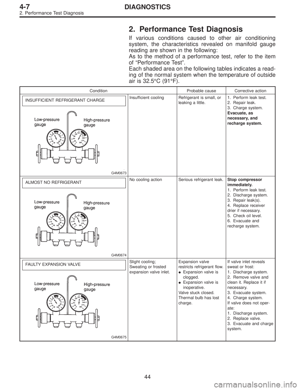
2. Performance Test Diagnosis
If various conditions caused to other air conditioning
system, the characteristics revealed on manifold gauge
reading are shown in the following:
As to the method of a performance test, refer to the item
of“Performance Test”.
Each shaded area on the following tables indicates a read-
ing of the normal system when the temperature of outside
air is 32.5°C (91°F).
Condition Probable cause Corrective action
INSUFFICIENT REFRIGERANT CHARGE
G4M0673
Insufficient cooling Refrigerant is small, or
leaking a little.1. Perform leak test.
2. Repair leak.
3. Charge system.
Evacuate, as
necessary, and
recharge system.
ALMOST NO REFRIGERANT
G4M0674
No cooling action Serious refrigerant leak.Stop compressor
immediately.
1. Perform leak test.
2. Discharge system.
3. Repair leak(s).
4. Replace receiver
drier if necessary.
5. Check oil level.
6. Evacuate and
recharge system.
FAULTY EXPANSION VALVE
G4M0675
Slight cooling;
Sweating or frosted
expansion valve inlet.Expansion valve
restricts refrigerant flow.
�Expansion valve is
clogged.
�Expansion valve is
inoperative.
Valve stuck closed.
Thermal bulb has lost
charge.If valve inlet reveals
sweat or frost:
1. Discharge system.
2. Remove valve and
clean it. Replace it if
necessary.
3. Evacuate system.
4. Charge system.
If valve does not oper-
ate:
1. Discharge system.
2. Replace valve.
3. Evacuate and charge
system.
44
4-7DIAGNOSTICS
2. Performance Test Diagnosis