Page 816 of 2248
3. CONDITIONS FOR COMPLETION OF TCS
SEQUENCE CONTROL
When the following conditions develop, the TCS sequence
control stops and ABS and TCS warning lights come on
while the ABS and TCS function will then stop. The brake
system functions as a conventional brake system.
1) When the speed of at least one wheel reaches 10 km/h
(6 MPH).
2) When terminal No. 4 is separated from ground. (When
select monitor is not used.)
3) When the brake pedal is depressed during sequence
control and the braking lamp switch is set to ON.
4) When TCS OFF switch is released. (When select moni-
tor is not used.)
5) After completion of the TCS sequence control.
6) When output signal to break TCS control is emitted from
ECM.
7) When malfunction is detected.
NOTE:
When malfunction has been detected and the TCS
sequence control operation has stopped, the trouble codes
are stored in memory.
97
4-4SERVICE PROCEDURE
20. Hydraulic Unit for ABS/TCS System
Page 1234 of 2248
 Prepare a general scan tool (OBD-II general scan tool)
required by SAE J1978.
2) Open the cover and connect the OBD-II ge")
OBD0006C
B: OBD-II GENERAL SCAN TOOL
1. HOW TO USE OBD-II GENERAL SCAN TOOL
1) Prepare a general scan tool (OBD-II general scan tool)
required by SAE J1978.
2) Open the cover and connect the OBD-II general scan
tool to the data link connector located in the lower portion
of the instrument panel (on the driver’s side), to the lower
cover.
3) Using the OBD-II general scan tool, call up diagnostic
trouble code(s) and freeze frame data.
OBD-II general scan tool functions consist of:
(1) MODE $01: Current powertrain diagnostic data
(2) MODE $02: Powertrain freeze frame data
(3) MODE $03: Emission-related powertrain diagnostic
trouble codes
(4) MODE $04: Clear/Reset emission-related diagnos-
tic information
(5) MODE $05: Oxygen sensor monitoring test results
Read out data according to repair procedures.
(For detailed operation procedures, refer to the OBD-II
General Scan Tool Operation Manual.)
NOTE:
For details concerning diagnostic trouble codes, refer to
the DIAGNOSTIC TROUBLE CODE (DTC) LIST [T11A0].
H2M1280
2. DATA LINK CONNECTOR (FOR OBD-II GENERAL
SCAN TOOL AND SUBARU SELECT MONITOR)
1) This connector is used both for OBD-II general scan
tools and Subaru Select Monitor.
2) Terminal No. 4 to No. 6 of data link connector is used
for Subaru Select Monitor signal.
CAUTION:
Do not connect scan tools other than OBD-II general
scan tools and Subaru Select Monitor, because the
circuit for Subaru Select Monitor may be damaged.
Terminal No. Contents Terminal No. Contents
1 Power supply 9 Blank
2 Blank10 K line of ISO 9141 CARB
3 Blank11 Blank
4 Subaru Select Monitor signal (ECM to Subaru Select monitor)* 12 Ground
5 Subaru Select Monitor signal (Subaru Select monitor to ECM)* 13 Ground
6 Subaru Select Monitor clock* 14 Blank
7 Blank15 Blank
8 Blank16 Blank
*: Circuit only for Subaru Select Monitor
28
2-7ON-BOARD DIAGNOSTICS II SYSTEM
3. Diagnosis System
Page 1235 of 2248

3. READ DATA LIST
�MODE $01
—Current powertrain diagnostic data—
Refers to data denoting the current operating condition of
analog input/output, digital input/output and/or the power-
train system.
A list of the support data and PID (Parameter Identification)
codes are shown in the following table.
PID DataUnit of measure
01 Number of emission-related powertrain trouble codes and MIL status ON/OFF
03 Fuel system control status—
04 Calculated engine load value%
05 Engine coolant temperature°C
06 Short term fuel trim%
07 Long term fuel trim%
0B Intake manifold absolute pressurekPa
0C Engine revolutionrpm
0D Vehicle speedkm/h
0E Ignition timing advance°
10 Air flow rate from mass air flow sensor g/sec
11 Throttle valve opening angle%
13 Check whether oxygen sensor is installed.—
14 Oxygen sensor output voltage and short term fuel trim associated with oxygen sensor—bank 1 V and %
15 Oxygen sensor output voltage and short term fuel trim associated with oxygen sensor—bank 2 V and %
1C On-board diagnosis system—
NOTE:
Refer to OBD-II general scan tool manufacturer’s instruc-
tion manual to access generic OBD-II PIDs (MODE $01).
29
2-7ON-BOARD DIAGNOSTICS II SYSTEM
3. Diagnosis System
Page 1236 of 2248

�MODE $02
—Powertrain freeze frame data—
Refers to data denoting the operating condition when
trouble is sensed by the on-board diagnosis system.
A list of the support data and PID (Parameter Identification)
codes are shown in the following table.
PID DataUnit of measure
02 Trouble code that caused CARB required freeze frame data storage—
03 Fuel system control status—
04 Calculated engine load value%
05 Engine coolant temperature°C
06 Short term fuel trim%
07 Long term fuel trim%
0B Intake manifold absolute pressurekPa
0C Engine revolutionrpm
0D Vehicle speedkm/h
NOTE:
Refer to OBD-II general scan tool manufacturer’s instruc-
tion manual to access freeze frame data (MODE $02).
�MODE $03
—Emission-related powertrain diagnostic
trouble codes—
Refers to data denoting emission-related powertrain diag-
nostic trouble codes.
For details concerning diagnostic trouble codes, refer to
the DIAGNOSTIC TROUBLE CODE (DTC) LIST [T11A0].
NOTE:
Refer to OBD-II general scan tool manufacturer’s instruc-
tion manual to access emission-related powertrain diag-
nostic trouble codes (MODE $03).
30
2-7ON-BOARD DIAGNOSTICS II SYSTEM
3. Diagnosis System
Page 1239 of 2248
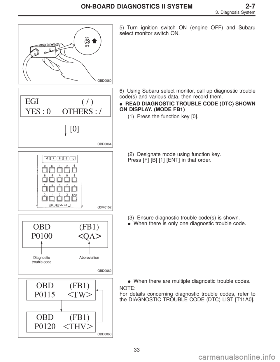
OBD0060
5) Turn ignition switch ON (engine OFF) and Subaru
select monitor switch ON.
OBD0064
6) Using Subaru select monitor, call up diagnostic trouble
code(s) and various data, then record them.
�READ DIAGNOSTIC TROUBLE CODE (DTC) SHOWN
ON DISPLAY. (MODE FB1)
(1) Press the function key [0].
G3M0152
(2) Designate mode using function key.
Press [F] [B] [1] [ENT] in that order.
OBD0062
(3) Ensure diagnostic trouble code(s) is shown.
�When there is only one diagnostic trouble code.
OBD0063
�When there are multiple diagnostic trouble codes.
NOTE:
For details concerning diagnostic trouble codes, refer to
the DIAGNOSTIC TROUBLE CODE (DTC) LIST [T11A0].
33
2-7ON-BOARD DIAGNOSTICS II SYSTEM
3. Diagnosis System
Page 1269 of 2248
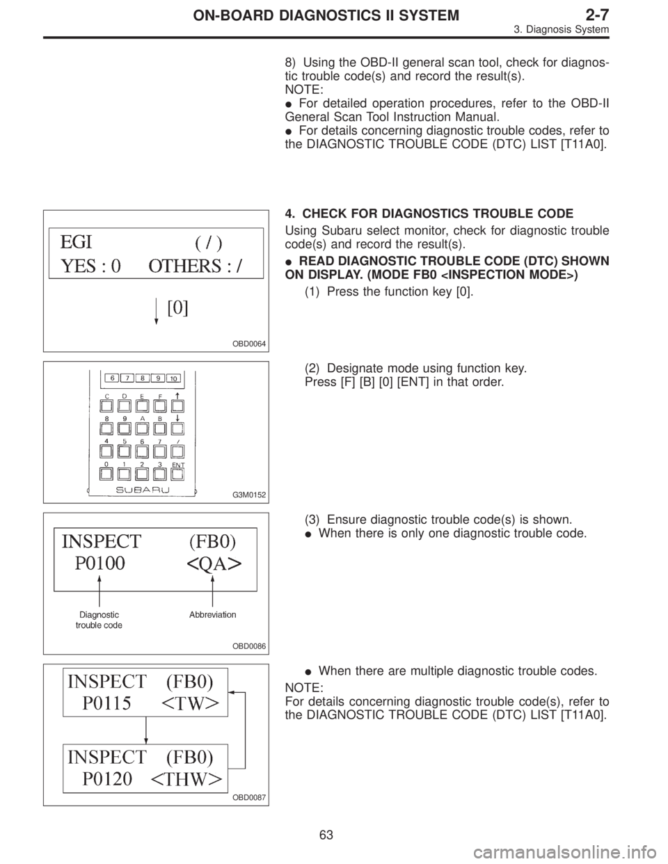
8) Using the OBD-II general scan tool, check for diagnos-
tic trouble code(s) and record the result(s).
NOTE:
�For detailed operation procedures, refer to the OBD-II
General Scan Tool Instruction Manual.
�For details concerning diagnostic trouble codes, refer to
the DIAGNOSTIC TROUBLE CODE (DTC) LIST [T11A0].
OBD0064
4. CHECK FOR DIAGNOSTICS TROUBLE CODE
Using Subaru select monitor, check for diagnostic trouble
code(s) and record the result(s).
�READ DIAGNOSTIC TROUBLE CODE (DTC) SHOWN
ON DISPLAY. (MODE FB0 )
(1) Press the function key [0].
G3M0152
(2) Designate mode using function key.
Press [F] [B] [0] [ENT] in that order.
OBD0086
(3) Ensure diagnostic trouble code(s) is shown.
�When there is only one diagnostic trouble code.
OBD0087
�When there are multiple diagnostic trouble codes.
NOTE:
For details concerning diagnostic trouble code(s), refer to
the DIAGNOSTIC TROUBLE CODE (DTC) LIST [T11A0].
63
2-7ON-BOARD DIAGNOSTICS II SYSTEM
3. Diagnosis System
Page 1569 of 2248
 indicates a“ten”, and the
short se")
2. HOW TO READ TROUBLE CODE OF INDICATOR
LIGHT
The AT OIL TEMP indicator light flashes the code corre-
sponding to the faulty part.
The long segment (1.2 sec on) indicates a“ten”, and the
short segment (0.2 sec on) signifies a“one”.
B3M0193A
E: CLEAR MEMORY
Current trouble codes shown on the display are cleared by
turning the ignition switch OFF after conducting on-board
diagnostic operation. Previous trouble codes, however,
cannot be cleared since they are stored in the TCM
memory which is operating on the back-up power supply.
These trouble codes can be cleared by removing the speci-
fied fuse (located under the right lower portion of the instru-
ment panel).
CLEAR MEMORY:
Removal of No. 14 fuse (for at least one minute)
�The No. 14 fuse is located in the line to the memory
back-up power supply of the TCM and ABS/TCS control
module. Removal of this fuse clears the previous trouble
codes stored in the TCM and ABS/TCS control module
memory.
�Be sure to remove the No. 14 fuse for at least the speci-
fied length of time. Otherwise, trouble codes may not be
cleared.
14
3-2AUTOMATIC TRANSMISSION AND DIFFERENTIAL
6. Diagnostic Chart for On-board Diagnostic System
Page 1610 of 2248
8. Diagnostic Chart with Select Monitor
A: BASIC DIAGNOSTIC CHART
If no trouble codes appear in the on-board diagnostic
operation (although problems have occurred or are
occurring), measure performance characteristics of
sensors, actuators, etc., in the“F”mode (select monitor
function), and compare with the“basic data”to determine
the cause of problems.
Trouble occurs.
No trouble codes appear in on-board diagnostic operation.
Measure each item in select mode function.
Compare measured values with basic data.
Determine item which is outside basic data specifications.
Check sensor and actuator affected.
�
�
�
�
�
55
3-2AUTOMATIC TRANSMISSION AND DIFFERENTIAL
8. Diagnostic Chart with Select Monitor

, measure performanc")