Page 1635 of 2248

or more for at least 20 seconds. If a problem is found, the
A.B.S")
B: INSPECTION MODE
The on-board diagnosis system is designed to detect prob-
lems after the vehicle has been driven at 10 km/h (6 MPH)
or more for at least 20 seconds. If a problem is found, the
A.B.S. warning light will illuminate to inform the driver of the
occurrence of a problem. When the warning light is on, the
A.B.S. system will be inactive and the normal braking func-
tion will work. It is possible for a maximum of three trouble
codes to be stored in memory until cleared.
B4M0082A
C: TROUBLE CODES
When on-board diagnosis of the A.B.S. control module
detects a problem, the information (up to a maximum of
three) will be stored in the EEP ROM as a trouble code.
When there are more than three, the most recent three will
be stored. (Stored codes will stay in memory until they are
cleared.)
1. CALLING UP A TROUBLE CODE
1) Take out diagnosis connector from side of driver’s seat
heater unit.
2) Turn ignition switch OFF.
3) Connect diagnosis connector terminal 6 (terminal L) to
diagnosis terminal.
4) Turn ignition switch ON.
5) A.B.S. warning light is set in the diagnostic mode and
blinks to identify trouble code.
6) After the start code (11) is shown, the trouble codes will
be shown in order of the last information first.
These repeat for a maximum of 5 minutes.
NOTE:
When there are no trouble codes in memory, only the start
code (11) is shown.
B4M0232A
8
4-4aBRAKES
6. Diagnostics Chart for On-board Diagnosis System
Page 1644 of 2248
—
DIAGNOSIS:
�Faulty A.B.S. sensor
�Faulty harness
�Faulty A.B.S. control module
TROUBLE SYMPTOM:
�")
C: TROUBLE CODE 21, 23, 25 AND 27
—FAULTY A.B.S. SENSOR (OPEN CIRCUIT
OR INPUT VOLTAGE EXCESSIVE)—
DIAGNOSIS:
�Faulty A.B.S. sensor
�Faulty harness
�Faulty A.B.S. control module
TROUBLE SYMPTOM:
�A.B.S. does not operate.
NOTE:
Trouble codes 21, 23, 25, and 27 will not be stored while
vehicle is stationary and can’t specify problem location.
Drive vehicle first, perform diagnosis and read trouble
code.
1. Check resistance of A.B.S. sensor to
A.B.S. control module side.
OK
�Not OK
4. Check resistance of A.B.S. sensor.
Not OK OK
Replace A.B.S. sensor.
Repair harness/connector.
2. Check input signal of A.B.S. sensor to
A.B.S. control module side.
Not OK
�OK
Replace A.B.S. control module.
3. Check A.B.S. sensor mechanical trouble.
OK
�Not OK
Repair mechanical trouble.
Replace A.B.S. sensor.
NOTE:
When checking A.B.S. sensor, carefully bend or swing con-
nector and harness to check for improper contacts or open
circuits.
�
�
�
�
�
17
4-4aBRAKES
7. Diagnostics Chart with Trouble Code
Page 1694 of 2248
6. Diagnostics Chart for On-board
Diagnosis System
A: BASIC DIAGNOSTICS PROCEDURE
TROUBLE OCCURS.
Ask the customer when and how the
trouble occurred using interview
check list.
PRE-INSPECTION
INSPECTION MODE
CALLING UP A TROUBLE CODE.
�No trouble code is readable.
�
Inspection using Diagnostic Chart for
Warning Light Failure.
Record all trouble codes.
Trouble codes
are issued.
�Only the start code is issued.
Inspection using General Diagnostics
Chart
Perform diagnostics in accordance with trouble code.
Trouble code
designated.
�
Repair.�
Clear memory.
INSPECTION MODE
CALLING UP A TROUBLE CODE.
Only the start code is issued.
CONFIRMATION TEST
END
NOTE:
�To check harness for broken wires or short circuits,
shake it while holding it or the connector.
�When TCS warning light illuminates, read and record
trouble code indicated by TCS warning light.
�
�
�
�
�
�
�
�
�
�
�
�
13
4-4bBRAKES
6. Diagnostics Chart for On-board Diagnosis System
Page 1697 of 2248

C: INSPECTION MODE
The on-board diagnosis system is designed to detect prob-
lems while the vehicle is being driven. If a problem is found,
the ABS and TCS warning light will illuminate to inform the
driver of the occurrence of a problem. When the warning
light is on, the ABS/TCS system will be inactive and the
normal braking function will work. It is possible for the most
recent trouble code and history of problem to be stored in
memory until cleared.
B4M0082C
D: TROUBLE CODES
When on-board diagnosis of the ABS/TCS control module
detects a problem, the information will be stored in the EEP
ROM as a trouble code. (Stored codes will stay in memory
until they are cleared.)
1. CALLING UP A TROUBLE CODE
1) Take out diagnosis connector from side of driver’s seat
heater unit.
2) Turn ignition switch OFF.
3) Connect diagnosis connector terminal No. 4 to diagno-
sis terminal.
4) Turn ignition switch ON.
5) TCS warning light is set in the diagnostic mode and
blinks to identify trouble code.
6) After the start code (11) is shown, the trouble codes will
be shown in order of the last information first.
NOTE:
When there are no trouble codes in memory, only the start
code (11) is shown.
B4M0383A
16
4-4bBRAKES
6. Diagnostics Chart for On-board Diagnosis System
Page 1768 of 2248

Function code
Measuring
itemsContents to be monitored Scroll Ref. to 4-4b
Code Abbreviation
FB0 D⋅NEWThe most
recent failures
are displayed.Trouble codes, t")
3. FB MODE (TROUBLE CODES ARE DISPLAYED.)
Function code
Measuring
itemsContents to be monitored Scroll Ref. to 4-4b
Code Abbreviation
FB0 D⋅NEWThe most
recent failures
are displayed.Trouble codes, trouble spots and symptoms for the
most recent failure are displayed.Possible [T10B0]
FB1 D⋅ALLHistorical
troubles are
displayed.Trouble codes, trouble spots and symptoms for all
historical failures are displayed.Possible[T10B0]
4. FC MODE (TROUBLE CODES ARE ERASED.)
Function code
Measuring
itemsContents to be monitored Scroll Ref. to 4-4b
Code Abbreviation
FC0 D⋅CLRTrouble codes
are erased.Function of clearing trouble code stored in memory. Possible[T9K0]
5. FD MODE (SEQUENCE CHECK AND AIR RELEASE
MODE)
Function code
Measuring
itemsContents to be monitored Scroll Ref. to
Code Abbreviation
FD1 A⋅CHKABS
sequence
controlPerform ABS sequence control by operating valve
and pump motor sequentially.Impossible4-4
[W20D0]
FD2 T⋅CHKTCS
sequence
controlPerform TCS sequence control by operating the
valve and pump motor sequentially.Impossible4-4
[W20F0]
FD3 AIRAir bleeding
controlManually operate the valve and pump motor to
bleed air.Impossible4-4
[W19A0]
87
4-4bBRAKES
9. Select Monitor Function Mode
Page 1773 of 2248
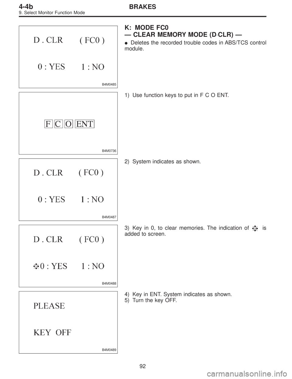
B4M0485
K: MODE FC0
—CLEAR MEMORY MODE (D⋅CLR)—
�Deletes the recorded trouble codes in ABS/TCS control
module.
B4M0736
1) Use function keys to put inFCOENT.
B4M0487
2) System indicates as shown.
B4M0488
3) Key in 0, to clear memories. The indication ofis
added to screen.
B4M0489
4) Key in ENT. System indicates as shown.
5) Turn the key OFF.
92
4-4bBRAKES
9. Select Monitor Function Mode
Page 1776 of 2248
CodeDisplay screen
(FB0)Diagnostic items (select monitor FB1) Display screen (FB1)Ref. to
4-4b
Abnormal stroke sen-
sor and stop light
switch54 PSS & BLSOpen/short")
Diagnostic items
(select monitor FB0)CodeDisplay screen
(FB0)Diagnostic items (select monitor FB1) Display screen (FB1)Ref. to
4-4b
Abnormal stroke sen-
sor and stop light
switch54 PSS & BLSOpen/short circuits of stroke sensor B.SW HARD [T10Y1]
Comparison of stroke sensor and acceleration B.SW SOFT(G) [T10Y2]
Comparison of stroke sensor and stop light switch B.SW SOFT(B) [T10Y3]
Comparison of stroke sensor and pump B.SW SOFT(P) [T10Y4]
Open circuit of stop light switch B.SW SOFT(O) [T10Y5]
Abnormal fluid level
sensor line57 FLUID LEVEL SS Abnormal fluid level sensor line FLUID LEVEL SS [T10Z0]
Abnormal pressure
switch58 PRESSURE SW Abnormal pressure switch PRESSURE SW [T10AA0]
Abnormal TCS1 valve 61 TCS1 VALVE Abnormal TCS1 valve TCS1 VALVE [T10AB0]
Abnormal TCS2 valve 62 TCS2 VALVE Abnormal TCS2 valve TCS2 VALVE [T10AC0]
1. IF THE SELECT MONITOR IS USED FOR
TROUBLESHOOTING, IT IS ADVISED TO FOLLOW
THE PROCEDURE BELOW
1) Activate function FB0 to read the most recent trouble
code and record it.
2) Activate function FB1 to read all trouble codes and
record them.
(If troubles occur in the wheel speed sensor, stop & brake
switch, valve relay or motor system, detailed data on
troubles are displayed by the FB1 function, allowing you to
easily locate points where need repair.)
3) Perform troubleshooting mainly in the FB1 mode.
95
4-4bBRAKES
10. Diagnostic Chart with Select Monitor
Page 1818 of 2248

B5M0115B
B: ON-BOARD DIAGNOSTIC
When the airbag system is in functioning condition, the
airbag warning light will remain on for 8 seconds and go out
when the ignition switch is set to ON.
If there is any malfunction, the airbag warning light will
either stay on or off continuously. In such cases, perform
on-board diagnostic in accordance with the specified pro-
cedure to determine trouble codes.
1) Turn ignition switch ON (with engine OFF).
2) Connect DIAG. terminal�
1to No. 1 terminal of diagno-
sis connector�
2located below lower cover.
3) Check in accordance with the trouble code indicated by
the AIRBAG warning light, and record the trouble codes.
4) Turn the ignition switch “OFF” and remove the DIAG.
terminal from No.1 terminal of diagnosis connector.
B5M0116B
C: CLEAR MEMORY
After eliminating problem as per trouble code, clear
memory as follows:
Make sure ignition switch is ON (and engine off). Connect
one DIAG. terminal�
1on diagnosis connector�2terminal
No. 1.
While warning light is flashing, connect the other DIAG.
terminal�
3on terminal No. 2 for at least three seconds.
After memory is cleared, normal warning light flashing rate
resumes. (Warning light flashes every 0.6 seconds ON-
OFF operation.) Memory cannot be cleared if any problem
exists.
After clear memory and then DIAG. terminals�
1and�3,
extract from diagnosis connector�
2.
9
5-5SUPPLEMENTAL RESTRAINT SYSTEM
4. Diagnostics Chart for On-board Diagnostic System
![SUBARU LEGACY 1995 Service Repair Manual 6. Diagnostics Chart for On-board
Diagnosis System
A: BASIC DIAGNOSTICS PROCEDURE
TROUBLE OCCURS.
Ask the customer when and how the
trouble occurred using interview
check list. <Ref. to 4-4b [T6B0].>](/manual-img/17/57432/w960_57432-1693.png "SUBARU LEGACY 1995 Service Repair Manual 6. Diagnostics Chart for On-board
Diagnosis System
A: BASIC DIAGNOSTICS PROCEDURE
TROUBLE OCCURS.
Ask the customer when and how the
trouble occurred using interview
check list. <Ref. to 4-4b [T6B0].>")