Page 801 of 2248

3. CONDITIONS FOR COMPLETION OF AIR
BLEEDING CONTROL
When any of the following conditions occurs, ABS and TCS
warning lights illuminate. Air bleeding control stops, while
the ABS and TCS function will then stop. The brake sys-
tem functions as a conventional brake system.
1) When the speed of at least one wheel reaches 10 km/h
(6 MPH).
2) When terminal No. 4 is separated from diagnosis termi-
nal. (When select monitor is not used.)
3) When pump motor remains ON for two minutes.
4) When TCS valve remains open for two minutes.
5) When outlet valve remains closed for two minutes.
6) When malfunction is detected.
NOTE:
When a malfunction is detected the air bleeding operation
stops and the trouble codes are stored in memory.
B4M0082C
C: AIR BLEEDING CONTROL WITH
DIAGNOSIS CONNECTOR
1) Connect diagnosis terminals to terminal No. 4 of the
diagnosis connector beside driver’s seat heater unit.
B4M0621A
2) Start the engine while pushing TCS OFF switch.
NOTE:
Keep the TCS OFF switch depressed even after the engine
has started.
3) After ABS and TCS warning lights go out, depress
brake pedal within 0.5 seconds.
4) After ensuring TCS ON indicator illuminates, release
TCS OFF switch and brake pedal.
5) Air bleeding control operation starts.
82
4-4SERVICE PROCEDURE
19. Air Bleeding (With TCS model)
Page 804 of 2248
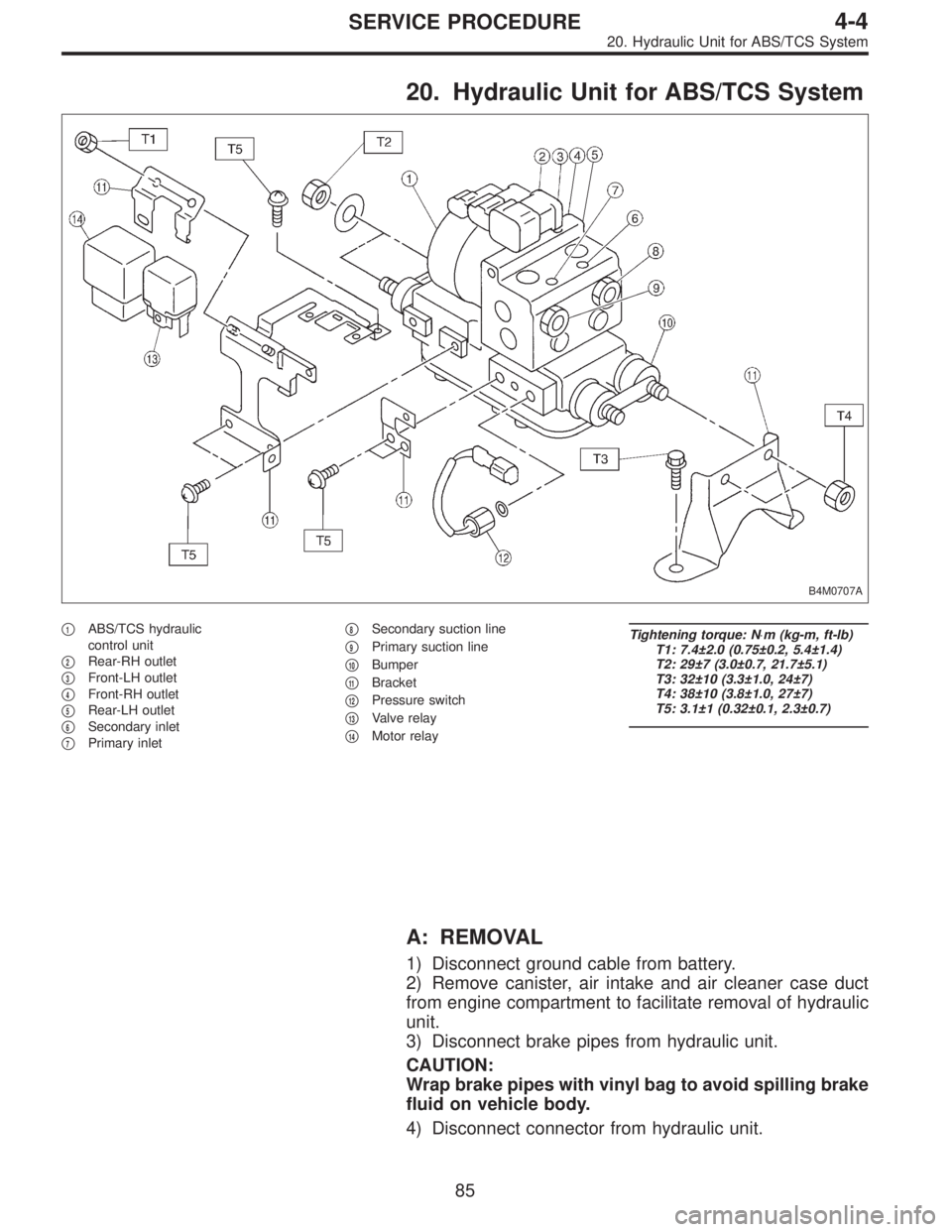
20. Hydraulic Unit for ABS/TCS System
B4M0707A
�1ABS/TCS hydraulic
control unit
�
2Rear-RH outlet
�
3Front-LH outlet
�
4Front-RH outlet
�
5Rear-LH outlet
�
6Secondary inlet
�
7Primary inlet�
8Secondary suction line
�
9Primary suction line
�
10Bumper
�
11Bracket
�
12Pressure switch
�
13Valve relay
�
14Motor relay
Tightening torque: N⋅m (kg-m, ft-lb)
T1: 7.4±2.0 (0.75±0.2, 5.4±1.4)
T2: 29±7 (3.0±0.7, 21.7±5.1)
T3: 32±10 (3.3±1.0, 24±7)
T4: 38±10 (3.8±1.0, 27±7)
T5: 3.1±1 (0.32±0.1, 2.3±0.7)
A: REMOVAL
1) Disconnect ground cable from battery.
2) Remove canister, air intake and air cleaner case duct
from engine compartment to facilitate removal of hydraulic
unit.
3) Disconnect brake pipes from hydraulic unit.
CAUTION:
Wrap brake pipes with vinyl bag to avoid spilling brake
fluid on vehicle body.
4) Disconnect connector from hydraulic unit.
85
4-4SERVICE PROCEDURE
20. Hydraulic Unit for ABS/TCS System
Page 808 of 2248
 Under the ABS sequence control, after the hydraulic
unit solenoid valve is driven, the operation of the hydraulic
unit can be checked by means of the brake tester or pres-
s")
D: ABS SEQUENCE CONTROL
1) Under the ABS sequence control, after the hydraulic
unit solenoid valve is driven, the operation of the hydraulic
unit can be checked by means of the brake tester or pres-
sure gauge.
2) ABS sequence control can be started by diagnosis con-
nector or select monitor.
B4M0082C
1. OPERATIONAL GUIDELINES OF THE ABS
SEQUENCE CONTROL WITH DIAGNOSIS
CONNECTOR
1) Connect diagnosis terminals to terminal No. 4 of the
diagnosis connector beside driver’s seat heater unit.
2) Ignition switch is turned to ON.
3) Make sure only the start code (code 11) is shown in
normal condition.
NOTE:
When trouble codes are stored in memory, repair the faulty
parts.
4) Set the speed of all wheels at 10 km/h (6 MPH) or less.
5) Turn ignition switch OFF.
6) Within 0.5 seconds after the ABS and TCS warning
lights go out, depress the brake pedal and hold it immedi-
ately after engine starts.
NOTE:
�When the ignition switch is set to on, the brake pedal
must not be depressed.
�Engine must operate.
�If brake pedal is not depressed within 0.5 seconds after
ABS and TCS warning lights go out, the trouble code mode
comes on.
7) After completion of ABS sequence control, turn ignition
switch OFF.
2. OPERATIONAL GUIDELINES OF THE ABS
SEQUENCE CONTROL WITH SELECT MONITOR
1) Connect select monitor to data link connector beside
driver’s seat heater unit.
2) Engine starts.
3) Put select monitor to TCS mode.
4) put select monitor to FBI mode. Make sure code 11 is
indicated.
NOTE:
When trouble codes are stored in memory, repair the faulty
parts.
89
4-4SERVICE PROCEDURE
20. Hydraulic Unit for ABS/TCS System
Page 814 of 2248
 Under the TCS sequence control, after the hydraulic
unit solenoid valve is driven, the operation of the hydraulic
unit can be checked by means of the brake tester or pres-
s")
F: TCS SEQUENCE CONTROL
1) Under the TCS sequence control, after the hydraulic
unit solenoid valve is driven, the operation of the hydraulic
unit can be checked by means of the brake tester or pres-
sure gauge.
2) TCS sequence control can be started by diagnosis con-
nector or select monitor.
B4M0082C
1. OPERATIONAL GUIDELINES OF THE TCS
SEQUENCE CONTROL WITH DIAGNOSIS
CONNECTOR
1) Connect diagnosis terminals to terminal No. 4 of the
diagnosis connector beside driver seat heater unit.
2) Ignition switch is turned to ON.
3) Make sure only the start code (code 11) is shown in
normal condition.
NOTE:
When trouble codes are stored in memory, repair the faulty
parts.
4) Set the speed of all wheels at 10 km/h (6 MPH) or less.
5) Turn ignition switch OFF.
6) Start engine, and within 0.5 seconds after the ABS
warning light and TCS warning light go out, press TCS OFF
switch. Within 1.0 second thereafter, release and press the
switch again. Then, keep the switch pressed.
NOTE:
�When the TCS sequence control is set to on, the brake
pedal must not be depressed.
�Engine must operate.
�When TCS OFF switch is not depressed within 0.5 sec-
onds after ABS and TCS warning lights turn off, the trouble
code mode comes on.
7) After completion of TCS sequence control, turn ignition
switch OFF.
95
4-4SERVICE PROCEDURE
20. Hydraulic Unit for ABS/TCS System
Page 815 of 2248
2. OPERATIONAL GUIDELINES OF THE TCS
SEQUENCE CONTROL WITH SELECT MONITOR
1) Connect select monitor to data link connector beside
driver’s seat heater unit.
2) Engine starts.
3) Put select monitor to TCS mode.
4) Put select monitor to FBI mode. Make sure code 11 is
indicated.
NOTE:
When trouble codes are stored in memory, repair the faulty
parts.
B4M0639
5) Press FD2 ENT key.
B4M0624
6) When the message shown in the figure is displayed,
press ENT key.
7) Checked portions will be displayed on select monitor.
B4M0627
8) When TCS sequence control cannot be started (by sys-
tem malfunction, etc.), the message shown in the figure will
be displayed.
NOTE:
Read the trouble codes. Repair faulty parts.
96
4-4SERVICE PROCEDURE
20. Hydraulic Unit for ABS/TCS System
Page 851 of 2248
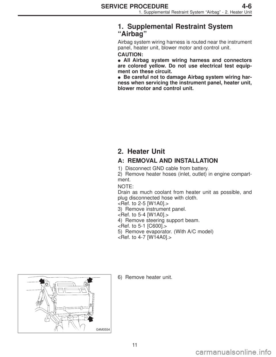
1. Supplemental Restraint System
“Airbag”
Airbag system wiring harness is routed near the instrument
panel, heater unit, blower motor and control unit.
CAUTION:
�All Airbag system wiring harness and connectors
are colored yellow. Do not use electrical test equip-
ment on these circuit.
�Be careful not to damage Airbag system wiring har-
ness when servicing the instrument panel, heater unit,
blower motor and control unit.
2. Heater Unit
A: REMOVAL AND INSTALLATION
1) Disconnect GND cable from battery.
2) Remove heater hoses (inlet, outlet) in engine compart-
ment.
NOTE:
Drain as much coolant from heater unit as possible, and
plug disconnected hose with cloth.
3) Remove instrument panel.
4) Remove steering support beam.
5) Remove evaporator. (With A/C model)
G4M0554
6) Remove heater unit.
11
4-6SERVICE PROCEDURE
1. Supplemental Restraint System“Airbag”- 2. Heater Unit
Page 852 of 2248
1. Supplemental Restraint System
“Airbag”
Airbag system wiring harness is routed near the instrument
panel, heater unit, blower motor and control unit.
CAUTION:
�All Airbag system wiring harness and connectors
are colored yellow. Do not use electrical test equip-
ment on these circuit.
�Be careful not to damage Airbag system wiring har-
ness when servicing the instrument panel, heater unit,
blower motor and control unit.
2. Heater Unit
A: REMOVAL AND INSTALLATION
1) Disconnect GND cable from battery.
2) Remove heater hoses (inlet, outlet) in engine compart-
ment.
NOTE:
Drain as much coolant from heater unit as possible, and
plug disconnected hose with cloth.
3) Remove instrument panel.
4) Remove steering support beam.
5) Remove evaporator. (With A/C model)
G4M0554
6) Remove heater unit.
11
4-6SERVICE PROCEDURE
1. Supplemental Restraint System“Airbag”- 2. Heater Unit
Page 1235 of 2248

3. READ DATA LIST
�MODE $01
—Current powertrain diagnostic data—
Refers to data denoting the current operating condition of
analog input/output, digital input/output and/or the power-
train system.
A list of the support data and PID (Parameter Identification)
codes are shown in the following table.
PID DataUnit of measure
01 Number of emission-related powertrain trouble codes and MIL status ON/OFF
03 Fuel system control status—
04 Calculated engine load value%
05 Engine coolant temperature°C
06 Short term fuel trim%
07 Long term fuel trim%
0B Intake manifold absolute pressurekPa
0C Engine revolutionrpm
0D Vehicle speedkm/h
0E Ignition timing advance°
10 Air flow rate from mass air flow sensor g/sec
11 Throttle valve opening angle%
13 Check whether oxygen sensor is installed.—
14 Oxygen sensor output voltage and short term fuel trim associated with oxygen sensor—bank 1 V and %
15 Oxygen sensor output voltage and short term fuel trim associated with oxygen sensor—bank 2 V and %
1C On-board diagnosis system—
NOTE:
Refer to OBD-II general scan tool manufacturer’s instruc-
tion manual to access generic OBD-II PIDs (MODE $01).
29
2-7ON-BOARD DIAGNOSTICS II SYSTEM
3. Diagnosis System
![SUBARU LEGACY 1995 Service Repair Manual 2. OPERATIONAL GUIDELINES OF THE TCS
SEQUENCE CONTROL WITH SELECT MONITOR
1) Connect select monitor to data link connector beside
driver’s seat heater unit. <Ref. to [W19D0] step 1).>
2) Engine star](/manual-img/17/57432/w960_57432-814.png "SUBARU LEGACY 1995 Service Repair Manual 2. OPERATIONAL GUIDELINES OF THE TCS
SEQUENCE CONTROL WITH SELECT MONITOR
1) Connect select monitor to data link connector beside
driver’s seat heater unit. <Ref. to [W19D0] step 1).>
2) Engine star")