1995 NISSAN ALMERA N15 Lamp
[x] Cancel search: LampPage 7 of 1701

PREPARATIONANDPRECAUTIONS
Service Notice
Supplemental RestraintSystem(SRS)"AIR
BAG" (DualAirBag System)
The Supplemental RestraintSystem"AirBag" usedalong withaseat belt, helps toreduce therisk or
severity ofinjury tothe driver andfront passenger inafrontal collision. TheSupplemental Restraint
System consists ofair bag modules (locatedinthe center ofthe steering wheelandonthe instrument
panel onthe passenger side),adiagnosis sensorunit,warning lamp,wiring harness andspiral cable.
Information necessarytoservice thesystem safelyisincluded inthe
RSsection
ofthis Service Manual.
WARNING:
• Toavoid rendering theSRS inoperative, whichcouldincrease therisk ofpersonal injuryordeath
in the event ofacollision whichwould resultinair bag inflation, allmaintenance mustbeperformed
by an authorized NISSANdealer.
• Improper maintenance, includingincorrectremovalandinstallation ofthe SRS, canlead topersonal
injury caused byunintentional activationofthe system.
Ii
Donot use electrical testequipment onany circuit related tothe SRS unless instructed tointhis
Service Manual. SRSwiring harnesses arecovered withyellow insulation eitherjustbefore the
harness connectors orfor the complete harness,foreasy identification.
•
Before proceeding withdisassembly, thor-
oughly cleantheoutside ofthe transaxle. Itis
important toprevent theinternal partsfrom
becoming contaminated bydirt orother for-
eign matter.
• Disassembly shouldbedone inaclean work
area.
• Use lint-free clothortowels forwiping parts
clean. Common shopragscanleave fibers
that could interfere withtheoperation ofthe
transaxle.
• Place disassembled partsinorder, onaparts
rack, foreasier andproper assembly.
• Allparts should becarefully cleaned-witha
general purpose, non-flammable solvent
before inspection orreassembly.
• Gaskets, sealsandO-rings shouldbe
replaced anytime thetransaxle isdisassem-
bled.
• Itis very important toperform functional tests
whenever theyareindicated. •
The valve bodycontains precision partsand
requires extremecarewhen partsare
removed andserviced. Placedisassembled
valve bodyparts inorder, onaparts rack,for
easier andproper assembly. Carewillalso
prevent springs andsmall partsfrombecom-
ing scattered orlost.
• Properly installedvales,sleeves, plugs,etc.
will slide along theirbores inthe valve body
under theirownweight.
• Before assembly, applyacoat ofrecom-
mended ATFtoall parts. Apply petroleum
jelly toprotect O-ringandseals, orhold bear-
ings andwashers inplace during assembly.
Do not use grease.
• Extremely careshould betaken toavoid dam-
age toO-rings, sealsandgaskets when
assembling.
• After overhaul, refillthetransaxle withnew
ATF.
•
Supplemental RestraintSystem(SRS)"AIR
BAG" (Single AirBag System)
The Supplemental RestraintSystem"AirBag" andused along withaseat belt,helps toreduce therisk
or severity ofinjury tothe driver inafrontal collision. TheSupplemental RestraintSystemconsists of
an air bag module (located inthe center ofthe steering wheel),adiagnosis sensorunit,warning lamp,
wiring harness andspiral cable. Information necessarytoservice thesystem safelyisincluded inthe
RS section
ofthis Service Manual.
WARNING:
• Toavoid rendering theSRS inoperative, whichcouldincrease therisk ofpersonal injuryordeath
in the event ofacollision whichwould resultinair bag inflation, allmaintenance mustbeperformed
by an authorized NISSANdealer.
• Improper maintenance, includingincorrectremovalandinstallation ofthe SRS, canlead topersonal
injury caused byunintentional activationofthe system.
• Donot use electrical testequipment onany circuit related tothe SRS unless instructed tointhis
Service Manual.
AT-7
Page 34 of 1701
(atP,)
p,
(Full throttle position)
~ThrOttle drum
Direction U
, ,-- p,
t
I ~.
(Idling
--r ~_ .)
position)
I
Direction T
Engine side"
bracket (at
P,)
~ Adjusting tube
Lock plate ON-VEHICLE
SERVICE
Throttle WireAdjustment (Cont'd)
1. Turn ignition switchtoOFF.
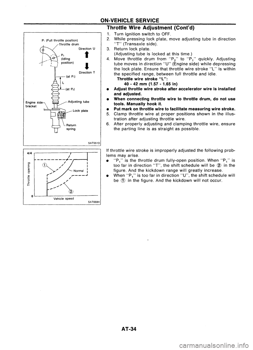
2. While pressing lockplate, moveadjusting tubeindirection
"T" (Transaxle side).
3. Return lockplate.
(Adjusting tubeislocked atthis time.)
4. Move throttle drumfrom
"P2"
to
"P
1"
quickly. Adjusting
tube moves indirection "U"(Engine side)while depressing
the lock plate. Ensure thatthrottle wirestroke "L"iswithin
the specified range,between fullthrottle andidle.
Throttle wirestroke "L":
40 -42
mm
(1.57 -1.65
in)
• Adjust throttle wirestroke afteraccelerator wireisinstalled
and adjusted.
• When connecting throttlewiretothrottle drum,donot use
tools. Manually hookit.
• Put mark onthrottle wiretofacilitate measuring wirestroke.
5. Clamp throttle wireatproper positions showninthe illus-
tration afteradjusting throttlewire.
6. After properly adjusting andclamping throttlewire,ensure
the parting lineisas straight aspossible.
SAT551D
4/4
Vehiclespeed
If
throttle wirestroke isimproperly adjustedthefollowing prob-
lems mayarise.
• "P
1"
isthe throttle drumfully-open position.When"P
1"
is
too farindirection
"T",
theshift schedule willbe
@
inthe
figure. Andthekickdown rangewillgreatly increase.
• When
"P1"
istoo farindirection "U",theshift schedule will
be
CD
inthe figure. Andthekickdown willnotoccur.
SAT669H
I
I
Normal :
,- .J
,/
/
,,~/~
/
---------1--
,/
'//
r-/
I
I
o
0>
c:
C
Q)
0-
o
~
2
£
I-
AT-34
Page 35 of 1701
ON-VEHICLESERVICE
Control CableInstallation andAdjustment
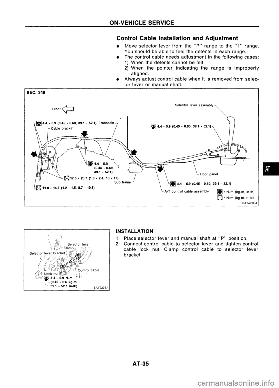
• Move selector leverfromthe"P" range tothe "1" range.
You should beable tofeel thedetents ineach range.
• The control cableneeds adjustment inthe following cases:
1) When thedetents cannotbefelt;
2) When thepointer indicating therange isimproperly
aligned.
• Always adjustcontrol cablewhenitis removed fromselec-
tor lever ormanual shaft.
SEC. 349
Floorpanel
\.~ 4.4-5.9 (0.45 •0.60. 39.1-52.1)
Front
<;:::J
~ 4.4 -5.9 (0.45 -0.60, 39.1-52.1)
Transax1,e
Cable bracket
•
~4.4 -5.9
(0.45 •0.60.
'I
39.1 -52.1)
~ 17.5 -23.7 (1.8•2.4, 13•17)
Sub frame Selector
leverassembly
~ 4.4•5.9 (0.45 -0.60, 39.1-52.1)
AIT control cableassembly
~:N.m (kg-m, in-Ib)
~ :N.m (kg-m, ft-Ib)
SAT499HA
•
SAT230EA
-{'
.~
did
Selector lever
I'y-
Clamp ,I.
'OJ} "
\ '4'i"" \.,)
I
,i
Selector leverbracket
\Vu
7//
;( ( .tll@:::(-c/",/.I
'''J)!I'r.
cY'?1I/'
i
j\\-.. )
~j
'.-It
( t:J-.,'-' ,
'.~/;,J~
A
'j
(,k;;.
l~\.\:\
D
eee:::
Control cable
t;-\
'II
Lock nut
~i'
l~}
I'
I
p
/.f .----
u
/,<\,:.~
4.4•5.9 N.m .."
- (0.45 -0.6
kg-m,
'~-39.1 -52.1 in-Ib)
INSTALLATION
1. Place selector leverandmanual shaftat"P" position.
2. Connect controlcabletoselector leverandtighten control
cable locknut.Clamp control cabletoselector lever
bracket.
AT-35
Page 36 of 1701
ON-VEHICLESERVICE
Control CableInstallation andAdjustment
(Cont'd)
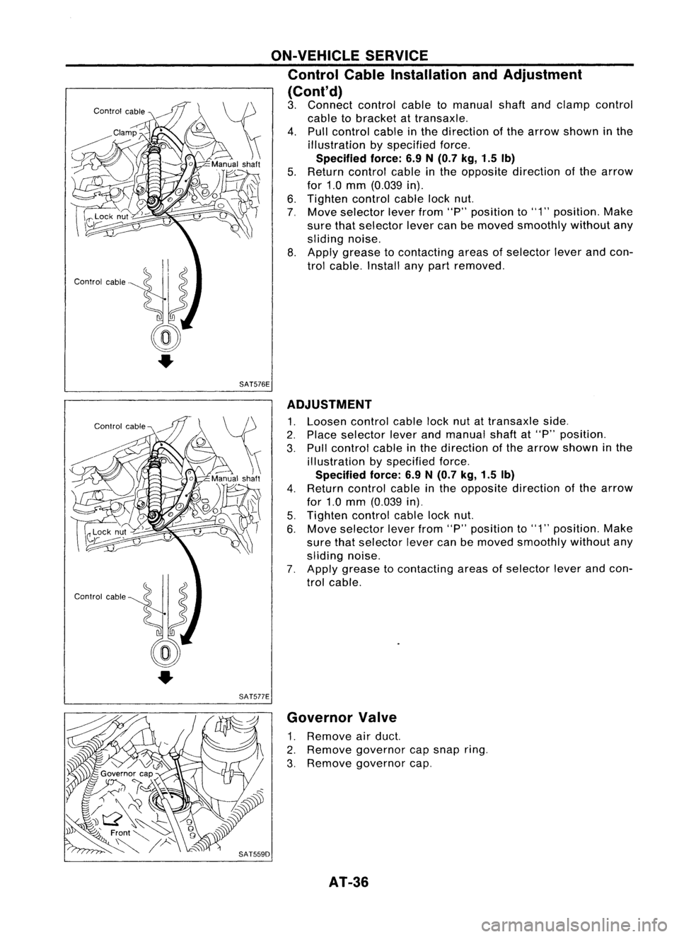
3. Connect controlcabletomanual shaftandclamp control
cable tobracket attransaxle.
4. Pull control cableinthe direction ofthe arrow shown inthe
illustration byspecified force.
Specified force:6.9N(0.7 kg,1.5Ib)
5. Return control cableinthe opposite direction ofthe arrow
for 1.0mm (0.039 in).
6. Tighten controlcablelocknut.
7, Move selector leverfrom"P"position to"1" position. Make
sure thatselector levercanbemoved smoothly withoutany
sliding noise.
8. Apply grease tocontacting areasofselector leverandcon-
trol cable. Installanypart removed.
SAT576E
SAT577E ADJUSTMENT
1. Loosen controlcablelocknutattransaxle side.
2. Place selector leverandmanual shaftat"P" position.
3. Pull control cableinthe direction ofthe arrow shown inthe
illustration byspecified force.
Specified force:6.9N
(0.7
kg,1.5 Ib)
4. Return control cableinthe opposite direction ofthe arrow
for 1.0mm (0.039 in).
5. Tighten controlcablelocknut.
6. Move selector leverfrom"P"position to"1" position. Make
sure thatselector levercanbemoved smoothly withoutany
sliding noise.
7. Apply grease tocontacting areasofselector leverandcon-
trol cable.
Governor Valve
1. Remove airduct.
2. Remove governor capsnap ring.
3, Remove governor cap,
AT-36
Page 46 of 1701
MAJOROVERHAUL
Shift Control Components
SATOBOI
Position
indicator
~ :N'm (kg-m. in-Ib)
~ :N'm (kg-m, tt-Ib)
~11.8
•14.7
(1.20 -1.50, 8.76•10.84)
~ 4.4 -5.9
(0.45 •0.6, 39.1 -52.1)
Control
leverassemblY~
Dust cover
I
~
4.4 •5.9 (0.45 •0.6, 39.1 •52.1)
'Return spring
m
Control cableclamp~
p
". '\ Selectorlever
rror.;
NT
"01
co,
'''''-y. "'.,,',,"
"II" •
S""",,,,"
k,o'
\
-~~
SEC.
349
AT-46
Page 193 of 1701
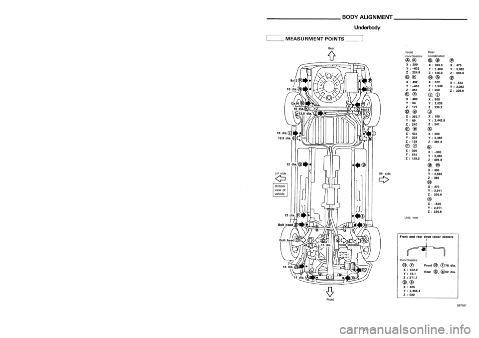
______ HANDLINGPRECAUTIONS FORPLASTICS __
BODYALIGNMENT _
Location OfPlastic Parts
Underbody
Kicking plate(PP)
Front
@,
076
dia.
Rear
@,@
62 dia.
Front
Rear
coordinates: coordinates:
@,@ @,@@
X :250
X:393.5
X:475
V :-632
V:1,460
V:3,082
Z :224.8
Z:126.9
Z:336.8
@,@
(8),
@
@
X :492 X
:572
X:-542
V :-450 V
:1,940
V:3,082
Z :355 Z
:200
Z:336.8
@,@
CD,
CD
X :406
X:600
V :64
V:2,035
Z :172
Z:235.2
@,@
Q)
X :352.7 X
:150
V :69 V
:2,442.9
Z :240 Z
:241
@,
@
@
X :432
X:300
V :338
V:2,480
Z :128
Z:381.8
(f),
CD
@
X :395
X:-300
V :515
V:2,480
Z :129.2
Z:405.8
@,
@)
X :393
Y :2,560
Z :365
@
X :470
Y :2,911
Z :339.6
@
X :-539
Y :2,911
Z :339.6
Unit: mm
Coordinates:
@,0
X :522.2
V :18.1
Z :571.7
@,@ X :465
V :2,456.4
Z :522
Front
andrear strut tower centers
I
~t-~
Rear
(f
••@
LH side
RHside
Q
Q
Bottom
view of
,1
vehicle
__
MEASURMENT POINTS__
Glove box(PPC)
Side
wind molding(PVC)
Cluster lidC(PPC)
Instrument
panel(PPC)
Console box(PPC)
5-door
Hatchback
Cluster lidA(PPC)
~----_/
Front
pillargarnish(PPC)
Side
wind molding(PVC)
Back doorfinisher(ABS)
Roof
spoilar(FRP)
3-doorHatchback
Center pillarlower garnish(PP)
Center pillarupper garnish(PPC)
Rear pillar garnish(PPC)
High
mounted stoplamp
(Lens: PMMA )
Housing: ABS
FrontSBT097
-27-
-18-
Page 194 of 1701
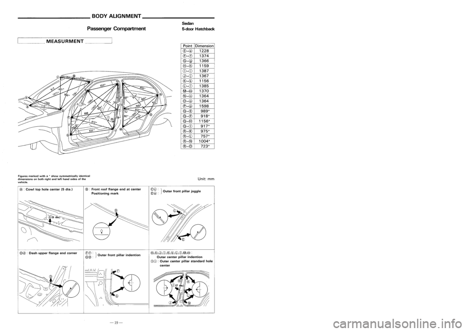
__________ BODYALIGNMENT _
_HANDLINGPRECAUTIONS FORPLASTICS _
Passenger Compartment Sedan
5-door Hatchback Location
OfPlastic Parts
Side turnsignal lamplens
(Lens: AS)
Housing: ASS
Wind-shield molding
(Upper: PVC )
Side:Stainless+PVC
Doorout-side molding
(Stainless+PVC)
Wheel cover
(Full cover: PP+PA6 )
Half cover: PA66+PPO
Center cap:PA6
Door
mirror
(Housing: AAS)
Garnish: ASS
Front turnsignal lamp
(Lens: PMMA)
Housing: PP
Fog
lamp
(Lens: Glass)
Housing: PP
Head
lamp
(Lens: Glass)
Housing: pp
Radiator grille
(ABS)
Fog lamp finisher
(PM MA)
Front
bumper fascia
(PP)
Front airspoiler
(PP)
Point
Dimension
@-@
1228
CB-
@-@
1366
(8)-{6)
1159
CD--cD
1387
Q)-{J) 1367
@--@
1156
(b)--{[)
1385
~-4iV
1370
@~
1364
@~
1364
C'e)--@
1598
@--@
989*
@-{E)
918*
@~
1156*
@--{[)
917*
@~@
975*
@~(b)
757*
@~
1004*
@--@
723*
,
... ._MEASURMENT _
Figures marked witha
*
show symmetrically identical
dimensions onboth right andlefthand sides ofthe
vehicle.
Unit:
mm
@ :
Cowl tophole center (5dia.)
CB>
:
Front roofflange endatcenter
Positioning mark ~~
~}Outer frontpillarjoggle
Sideguard molding (PVC)
Rear combination lamp
(Lens: PMMA)
Housing: PP
Door
outside handle
(Handle: POM )
Escutcheon: POM
Mud guard (TPR)
Rear
Windowmolding
(PVC)
-for Sedan
Rear bumper fascia
(PP)
License
lamp
(Lens: PC)
Housing: PP
Trunk
lidfinisher(pp)
-for Sedan
Rear
spoiler(PPO)
-for Sedan
High mounted stoplamp
(In Rear SpoilerType)
(Lens: PMMA)-for Sedan
Housing: ASS
(Fixed Trunk LidTipe)
(Lens: PC)-for Sedan
Housing: PP
(f3),Cfi),Q),CD,@,@,CD,CD,~,@ :
Outer center pillarindention
CDCD :
Outer center pillarstandard hole
center
CBCD:
}
~@:
Outerfrontpillar indention
@@
:
Dash upper flange endcorner
-19- -26-
Page 201 of 1701
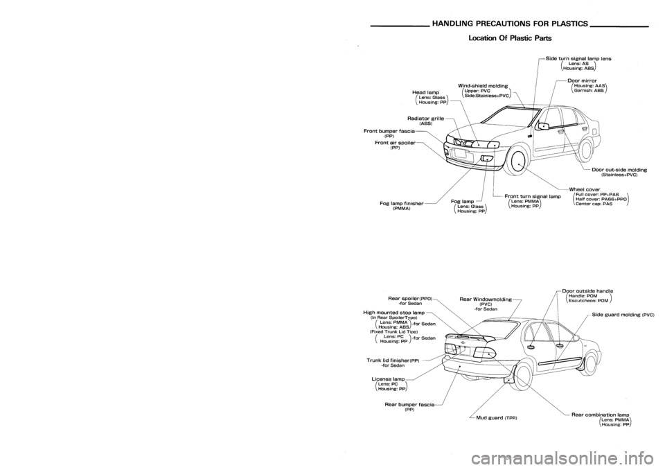
__________ BODYALIGNMENT _
_HANDLINGPRECAUTIONS FORPLASTICS _
Passenger Compartment Sedan
5-door Hatchback Location
OfPlastic Parts
Side turnsignal lamplens
(Lens: AS)
Housing: ASS
Wind-shield molding
(Upper: PVC )
Side:Stainless+PVC
Doorout-side molding
(Stainless+PVC)
Wheel cover
(Full cover: PP+PA6 )
Half cover: PA66+PPO
Center cap:PA6
Door
mirror
(Housing: AAS)
Garnish: ASS
Front turnsignal lamp
(Lens: PMMA)
Housing: PP
Fog
lamp
(Lens: Glass)
Housing: PP
Head
lamp
(Lens: Glass)
Housing: pp
Radiator grille
(ABS)
Fog lamp finisher
(PM MA)
Front
bumper fascia
(PP)
Front airspoiler
(PP)
Point
Dimension
@-@
1228
CB-
@-@
1366
(8)-{6)
1159
CD--cD
1387
Q)-{J) 1367
@--@
1156
(b)--{[)
1385
~-4iV
1370
@~
1364
@~
1364
C'e)--@
1598
@--@
989*
@-{E)
918*
@~
1156*
@--{[)
917*
@~@
975*
@~(b)
757*
@~
1004*
@--@
723*
,
... ._MEASURMENT _
Figures marked witha
*
show symmetrically identical
dimensions onboth right andlefthand sides ofthe
vehicle.
Unit:
mm
@ :
Cowl tophole center (5dia.)
CB>
:
Front roofflange endatcenter
Positioning mark ~~
~}Outer frontpillarjoggle
Sideguard molding (PVC)
Rear combination lamp
(Lens: PMMA)
Housing: PP
Door
outside handle
(Handle: POM )
Escutcheon: POM
Mud guard (TPR)
Rear
Windowmolding
(PVC)
-for Sedan
Rear bumper fascia
(PP)
License
lamp
(Lens: PC)
Housing: PP
Trunk
lidfinisher(pp)
-for Sedan
Rear
spoiler(PPO)
-for Sedan
High mounted stoplamp
(In Rear SpoilerType)
(Lens: PMMA)-for Sedan
Housing: ASS
(Fixed Trunk LidTipe)
(Lens: PC)-for Sedan
Housing: PP
(f3),Cfi),Q),CD,@,@,CD,CD,~,@ :
Outer center pillarindention
CDCD :
Outer center pillarstandard hole
center
CBCD:
}
~@:
Outerfrontpillar indention
@@
:
Dash upper flange endcorner
-19- -26-