Page 1574 of 1701
ASSEMBLYI
RSSF30A
&
RSSF31 A
I
SMT720
c.
Install mainshaft assembly.
• Take carenottodamage oilchannel wheninserting main-
shaft intoclutch housing.
9. Apply grease toshifter caps,theninstall itto control
bracket. Installcontrol bracket with1st
&
2nd shift fork.
10. Install 3rd
&
4th and 5thshift forks.
11. Insert forkshaft.
• Apply multi-purpose greasetosupport springbefore install-
ing.
12. Install reverse idlerspacer.
13. Apply recommended sealanttomating surface ofclutch
housing.
14. Install transmission caseonclutch housing.
15. Measure totalturning torque.
Total (Final drive+Mainshaft) turningtorque(New
bearing): Refer toSOS, MT-62.
• When oldbearing isused again, turning torquewillbe
slightly lessthan theabove.
• Make suretorque isclose tothe specified range.
MT-32
Page 1575 of 1701

MAJOROVERHAUL
I
RS5F32A
I
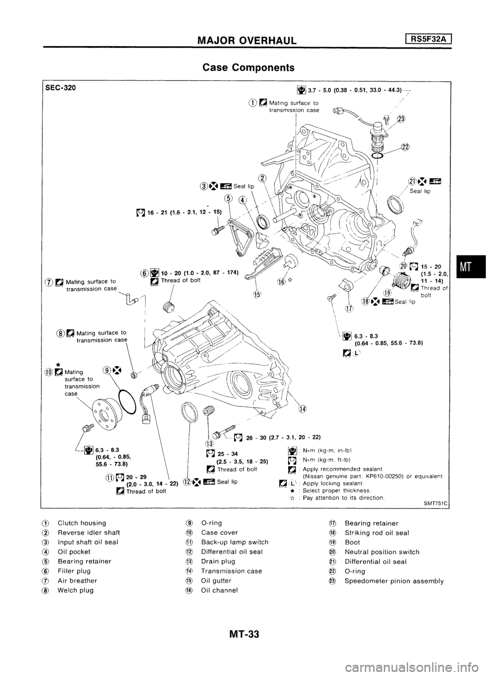
Case Components
•
\
\L~
6.3.8.3
(0.64 -0.85, 55.6-73.8)
~.L'
J
(15,'
~
3.7•5.0 (0.38 •0.51, 33.0-44.3)
CD ~
Mating surface to
transmission case~
I
;1
~3J
1J2»~
o//~
d~~~
!-~~
i~=1D.
(]?
CID.:.
m
Seal lip \
\
.
~)~
//\
1~
~'
(fl)
to.J
20-29 \
- (2.0-3.0, 14-22)
~ Thread ofbolt
@
~
Mating surface to
SEC.320
@~
10.20 (1.0-2.0, 87-174)
W ~
Mating surface to ~Thread ofbolt
"""mi"ioo '""
\1:.0
1 ~ /',
. WO,,~., .,.~
~~~> '\
t,,~~~~
o
I:::t:\ ~___-- __~
j)\~
~i)~/
(ro\~\~)
. ------ ~~,/ ~Q~
I
f""\
~~~ ..~ Q{
t~A
26-30 (2.7 -3.1, 20-22)
!13i
~ 25_34 ~N.m(kg-m, In-Ib\
(2.5 -3.5, 18-25)
A
N.m(kg-m, ft-Ib)
~ Thread ofbolt ~.Apply recommended sealant
(Nissan genuine part:KP610-00250) orequivalent
12)~.
m
Seal lip ~
,.1..',
Apply locking sealant
* :
Select proper thickness.
-tI .
Pay attention toits direction,
*
@~Mating
SMT751C
G)
Clutch housing
@
Reverse idlershaft
@
Input shaftoilseal
@
Oilpocket
@
Bearing retainer
@
Filler plug
(J)
Airbreather
@
Welch plug
(9)
O-ring
@
Case cover
CfD
Back-up lampswitch
@
Differential oilseal
@
Drain plug
@
Transmission case
@
Oilgutter
@
Oilchannel
@
Bearing retainer
@l
Striking rodoilseal
QID
Boot
@
Neutral position switch
@
Differential oilseal
@
O-ring
@
Speedometer pinionassembly
MT-33
Page 1594 of 1701
ST33290001
REPAIR
FORCOMPONENT PARTS
I
RS5F32A
I
Case Components (Cont'd)
2. Remove inputshaft rearbearing bytapping itfrom welch
plug hole.
SMT704B
3.Install welchplug.
• Apply recommended sealanttomating surface oftransmis-
sion case.
SMT705B
4.Install inputshaft rearbearing.
SMT706BA Mainshaft frontbearing andoilchannel
1. Remove mainshaft frontbearing retainer.
SMT707B
2.Remove mainshaft frontbearing.
3. Remove oilchannel.
SMT714BA MT-52
Page 1672 of 1701

ON-VEHICLESERVICE
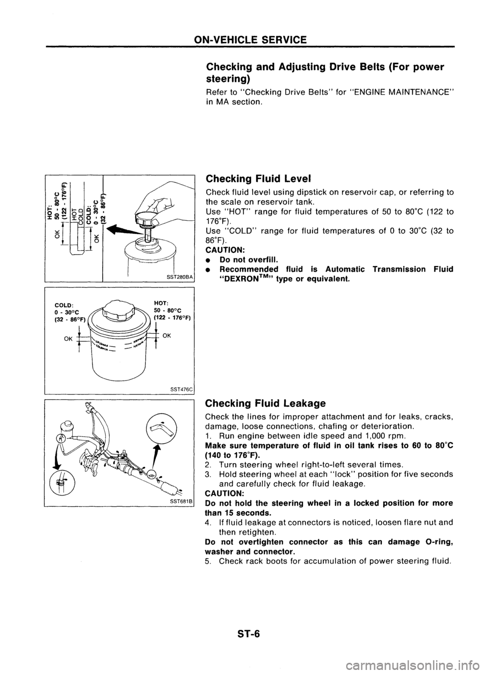
Checking andAdjusting DriveBelts(Forpower
steering)
Refer to"Checking DriveBelts" for"ENGINE MAINTENANCE"
in MA section.
SST476C
S
r
SST681B Checking
Fluidlevel
Check fluidlevel using dipstick onreservoir cap,orreferring to
the scale onreservoir tank.
Use "HOT" rangeforfluid temperatures of50 to80°C (122to
176°F).
Use "COLD" rangeforfluid temperatures of0to 30°C (32to
86°F).
CAUTION:
• Donot overfill.
• Recommended fluidisAutomatic Transmission Fluid
''DEXRON™,, typeorequivalent.
Checking Fluidleakage
Check thelines forimproper attachment andforleaks, cracks,
damage, looseconnections, chafingordeterioration.
1. Run engine between idlespeed and1,000 rpm.
Make suretemperature offluid inoil tank rises to60 to80°C
(140 to176°F).
2. Turn steering wheelright-to-Ieft severaltimes.
3. Hold steering wheelateach "lock" position forfive seconds
and carefully checkforfluid leakage.
CAUTION:
Do not hold thesteering wheelinalocked position formore
than 15seconds.
4. Iffluid leakage atconnectors isnoticed, loosenflarenutand
then retighten.
Do not overtighten connectorasthis candamage O-ring,
washer andconnector.
5. Check rackboots foraccumulation ofpower steering fluid.
ST-6
Page:
< prev 1-8 9-16 17-24