Page 711 of 1701
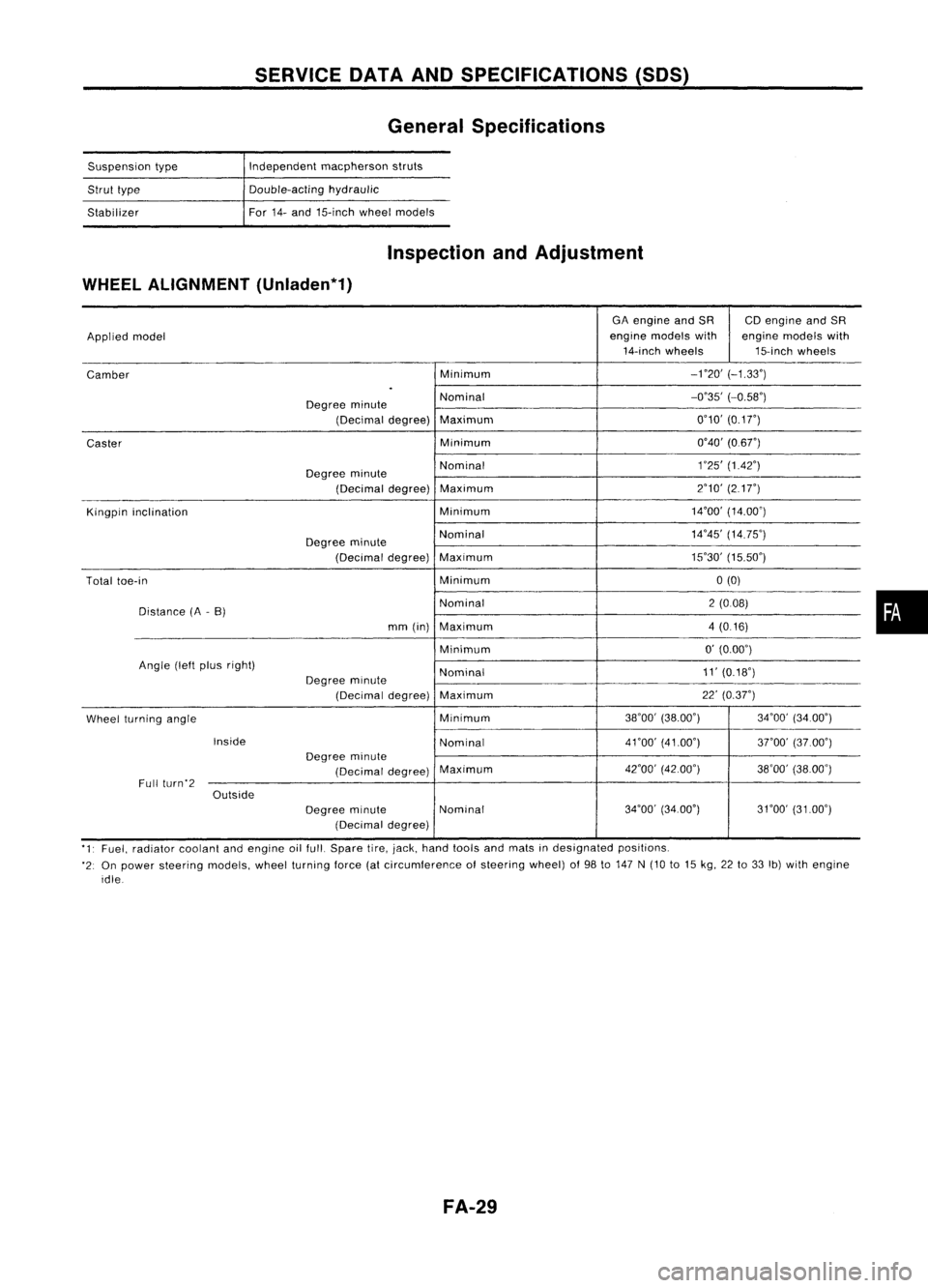
SERVICEDATAANDSPECIFICATIONS (50S)
General Specifications
Suspension type
Strut type
Stabilizer Independent
macpherson struts
Double-acting hydraulic
For 14-and 15-inch wheelmodels
Inspection andAdjustment
WHEEL ALIGNMENT (Unladen*1)
GAengine andSR CDengine andSR
Applied model engine
models with enginemodels with
14-inch wheels 15-inchwheels
Camber Minimum
-no'
(-1.33')
.
Degree minute Nominal
-0'35'
(-0.58')
(Decimal degree)Maximum 0'10'
(0.1
r)
Caster Minimum
0'40'(0.6r)
Degree minute Nominal
1
'25' (1.42')
(Decimal degree)Maximum 2'10'
(217")
Kingpin inclination Minimum14'00'
(14.00')
Degree minute Nominal
14'45'
(14.75')
(Decimal degree)Maximum 15'30'
(15.50')
Total toe-in Minimum0(0)
Distance (A-B) Nominal
2(008)
mm (in) Maximum 4(0.16)
Minimum 0'
(0.00')
Angle (leftplus right)
Nominal 11'
(0.18')
Degree minute
(Decimal degree)Maximum 22'
(0.37")
Wheel turning angle Minimum
38'00'
(38.00') 34'00'(34.00')
Inside Nominal4nO'
(41.00')
3rOO'(37.00')
Degree minute
(Decimal degree)Maximum
42'00'
(42.00')
38'00'(38.00')
Full (urn'2
Outside
Degreeminute Nominal 34'00'
(34.00') 31'00'(3100')
(Decimal degree)
'1' Fuel, radiator coolantandengine oilfull. Spare tire,jack, hand tools andmats indesignated positions.
'2: On power steering models,wheelturning force(atcircumference ofsteering wheel)of98 to147 N(10 to15 kg, 22to33 Ib)with engine
idle
FA-29
•
Page 1491 of 1701
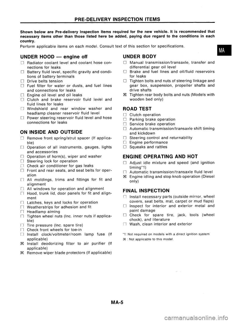
PRE-DELIVERYINSPECTIONITEMS
Shown belowarePre-delivery InspectionItemsrequired forthe new vehicle. Itis recommended that
necessary itemsotherthanthose listedherebeadded, payingdueregard tothe conditions ineach
country.
Perform applicable itemsoneach model. Consult textofthis section forspecifications .
UNDER HOOD-engine off
o
Radiator coolantlevelandcoolant hosecon-
nections forleaks
o
Battery fluidlevel, specific gravityandcondi-
tions ofbattery terminals
o
Drive beltstension
D
Fuel filter forwater ordusts, andfuel lines
and connections forleaks
[] Engine oillevel andoilleaks
D
Clutch andbrake reservoir fluidlevel and
fluid lines forleaks
o
Windshield andrear window washerand
headlamp cleanerreservoir fluidlevel
D
Power steering reservoir fluidlevel andhose
connections forleaks
ON INSIDE ANDOUTSIDE
D
Remove frontspring/strut spacer(Ifapplica-
ble)
D
Operation ofall instruments, gauges,lights
and accessories
o
Operation ofhorn(s), wiperandwasher
[] Steering lockforoperation
[] Check airconditioner forgas leaks
o
Front andrear seats, andseat belts foroper-
ation
n
All moldings, trimsandfittings forfitand
alignment
[J
Allwindows foroperation andalignment
n
Hood, trunklid,door panels forfitand align-
ment
[1
Latches, keysandlocks foroperation
rl
Weatherstrips foradhesion andfit
[l
Headlamp aiming
I~ Tighten wheelnuts(Inc. inner nutsifapplica-
ble)
IJ Tire pressure (Inc.spare tire)
Il
Check frontwheels fortoe-in
IJ Install clock/voltmeter/room lampfuse(If
applicable)
~ Install deodorizing filtertoair purifier (If
applicable)
~ Remove wiperbladeprotectors (Ifapplicable)
UNDER
BODY
o
Manual transmission/transaxle, transferand
differential gearoillevel
D
Brake andfuel lines andoil/fluid reservoirs
for leaks
D
Tighten boltsandnuts ofsteering linkageand
gear box,suspension, propellershaftsand
drive shafts
~ Tighten rearbody boltsandnuts (Models with
wooden bedonly)
ROAD TEST
D
Clutch operation
D
Parking brakeoperation
[J
Service brakeoperation
D
Automatic transmission/transaxle shifttiming
and kickdown
[] Steering controlandreturnability
o
Engine performance
D
Squeaks andrattles
ENGINE OPERATING ANDHOT
D
Adjust idlemixture andspeed (andignition
timing*1)
n
Automatic transmission/transaxle fluidlevel
~ Engine idlingandstop knob operation (Diesel
only)
FINAL INSPECTION
n
Install necessary parts(outside mirror,wheel
covers, seatbelts, mat,carpet ormud flaps)
[1
Inspect forinterior andexterior metaland
paint damage
[] Check forspare tire,jack, tools (wheel
chock), andliterature
n
Wash, cleaninterior andexterior
"1: Not required onmodels withadirect ignition system
~ :Not appiicable tothis model.
•
MA-5
Page 1494 of 1701
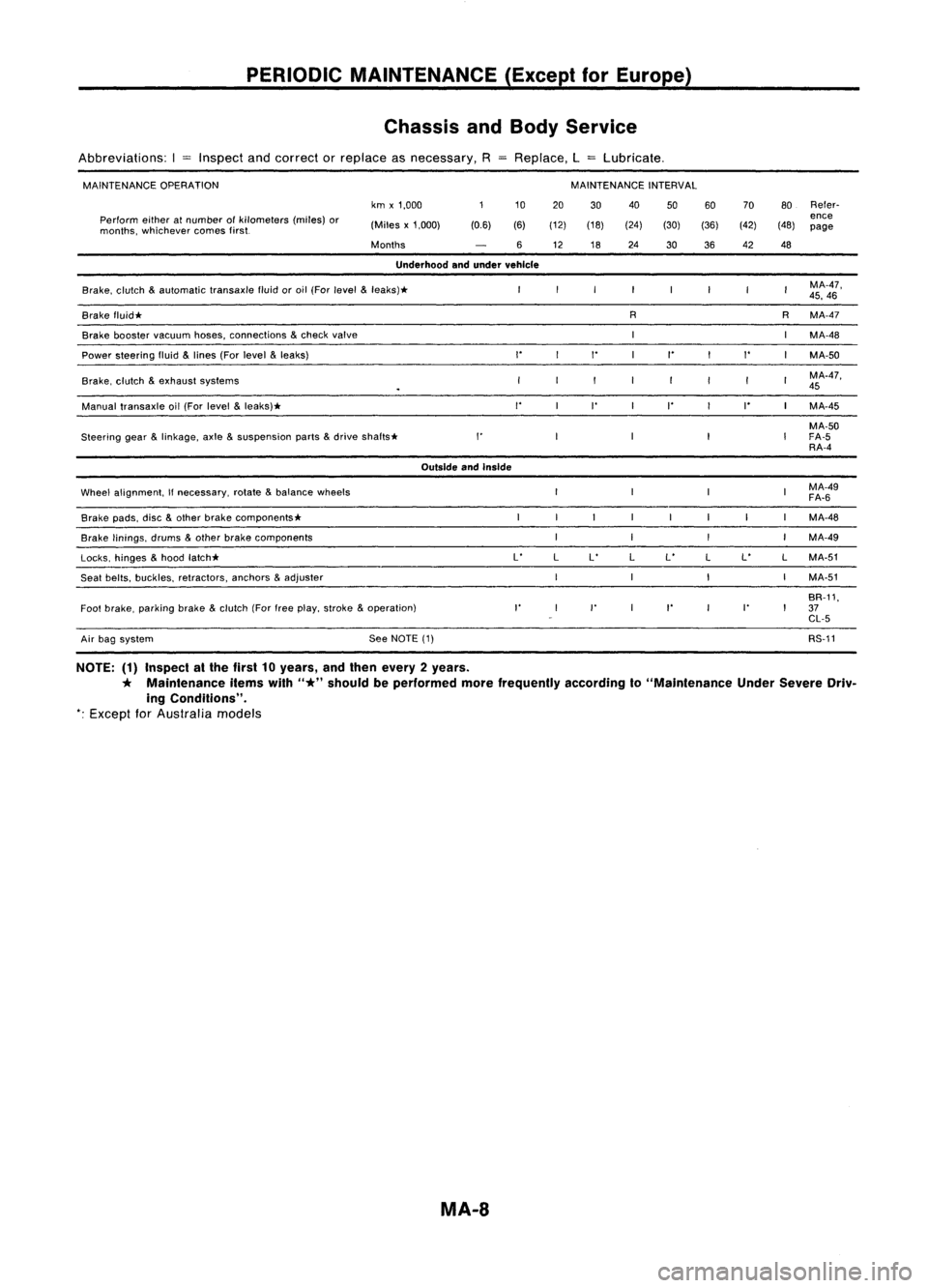
PERIODICMAINTENANCE (ExceptforEurope)
Chassis andBody Service
Abbreviations: I
=
Inspect andcorrect orreplace asnecessary, RReplace, L
=
Lubricate.
MAINTENANCE OPERATION MAINTENANCE
INTERVAL
km x1,000 10
20 30 40
5060 70
80Refer-
Perform eitheratnumber ofkilometers (miles)or
ence
months, whichever comesfirst. (Miles
x1,000) (0.6)(6)(12) (18) (24)(30)(36) (42)(48)
page
Months 612 1824
3036 42
48
Underhood andunder vehicle
Brake, clutch
&
automatic transaxlefluidoroil (For
level
&
leaks)* MA-47,
45, 46
Brake fluid* R
RMA-47
Brake booster
vacuum
hoses,connections
&
check
valve
MA-48
Power steering fluid
&
lines (For
level
&
leaks)
""
I'
"
MA-50
Brake, clutch
&
exhaust systems MA-47,
45
Manual transaxle oil(For level
&
leaks)*
"
I'
I' I'
MA-45
MA-50
Steering gear
&
linkage, axle
&
suspension parts
&
drive
shafts* I'
FA-5
RA-4
Outside andInside
Wheel alignment,
If
necessary, rotate
&
balance wheels MA-49
FA-6
Brake pads,disc
&
other brake components* MA-48
Brake linings, drums
&
other brake components MA-49
Locks, hinges
&
hood latch* L'
LL' LL'
LL'
LMA-51
Seat belts, buckles, retractors, anchors
&
adjuster MA-51
BR-11,
Foot brake, parking brake
&
clutch (Forfreeplay, stroke
&
operation)
I'
I'
I'
I'
37
CL-5
Air bag system See
NOTE (1) RS-11
NOTE: (1)Inspect atthe first 10years, andthen every 2years.
*
Maintenance itemswith
"*"
should beperformed morefrequently accordingto"Maintenance UnderSevere Driv-
ing Conditions".
*:
Except
for
Australia models
MA-8
Page 1498 of 1701
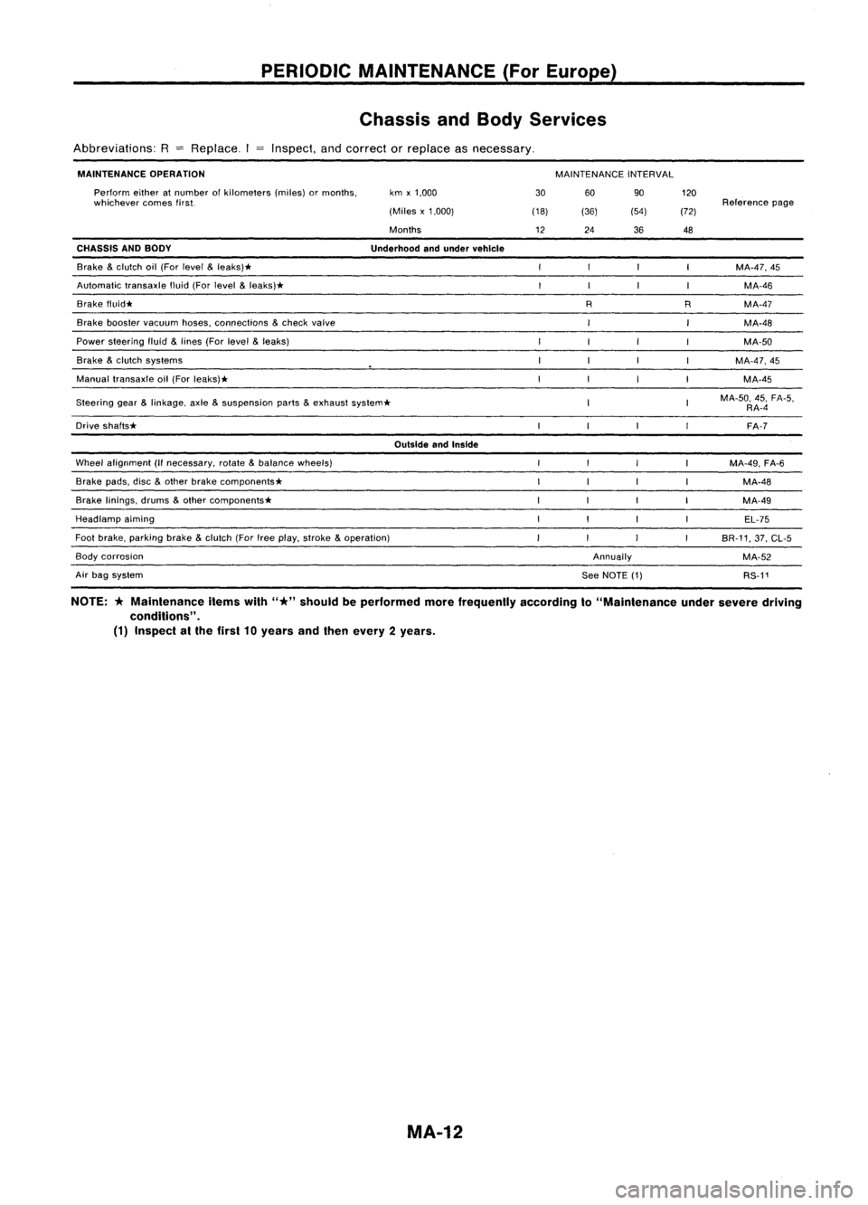
PERIODICMAINTENANCE (ForEurope)
Chassis andBody Services
Abbreviations: R
=
Replace. Inspect,andcorrect orreplace asnecessary.
MAINTENANCE OPERATION
MAINTENANCEINTERVAL
Steering gear
&
linkage, axle
&
suspension parts
&
exhaust system*
OutsideandInside
Wheel alignment (Ifnecessary, rotate
&
balance wheels)
Brake pads,disc
&
other brake components*
Brake linings, drums
&
other components*
Headlamp aiming
Foot brake, parking brake
&
clutch (Forfreeplay, stroke
&
operation)
Annually120
Reference page
(72)
48
MA-47,45MA-46
R MA-47
MA-48
MA-50
MA-47,45 MA-45
MA-50, 45,FA-5,
RA-4
FA-7
MA-49, FA-6
MA-48
MA-49 EL-75
BR-11, 37,CL-5
MA-52 RS-11
90
(54)
36
R
60
See NOTE (1)
(36)
24
30
(18)
12
km
x1,000
(Miles x1,000)
Months
Underhood andunder vehicle
Perform
eitheratnumber ofkilometers (miles)ormonths,
whichever comesfirst.
Brake booster vacuum hoses,connections
&
check valve
Brake
&
clutch oil(For level
&
leaks)*
Automatic transaxlefluid(Forlevel
&
leaks)*
Brake f1uid*
CHASSIS
ANDBODY
Power steering fluid
&
lines (Forlevel
&
leaks)
Brake
&
clutch systems
Manual transaxle oil(For leaks)*
Drive shafts*
Air bag system
Body
corrosion
NOTE:
*
Maintenance itemswith
"*"
should beperformed morefrequently accordingto"Maintenance undersevere driving
conditions" .
(1) Inspect atthe first 10years andthen every 2years.
MA-12
Page 1609 of 1701
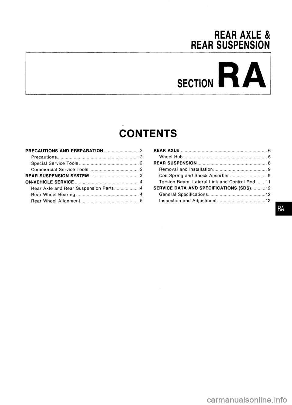
REARAXLE
&
REAR SUSPENSION
SECTION
RA
CONTENTS
PRECAUTIONS ANDPREPARATION 2
Precautions 2
Special ServiceTools 2
Commercial ServiceTools 2
REAR SUSPENSION
SySTEM 3
ON-VEHICLE SERVICE
4
Rear AxleandRear Suspension Parts 4
Rear Wheel Bearing 4
Rear Wheel Alignment 5
REAR
AXLE 6
Wheel Hub 6
REAR SUSPENSION 8
Removal andInstallation 9
Coil Spring andShock Absorber 9
Torsion Beam,Lateral LinkandControl Rod 11
SERVICE DATAANDSPECIFICATIONS (SDS)12
General Specifications 12
Inspection andAdjustment. 12
•
Page 1610 of 1701
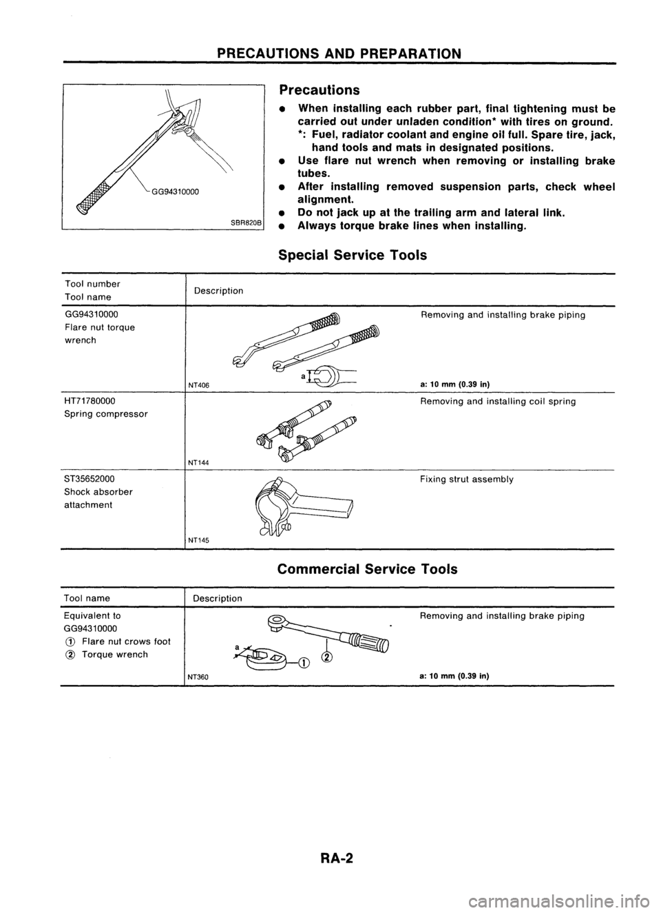
PRECAUTIONSANDPREPARATION
SBR820B Precautions
• When installing eachrubber part,finaltightening mustbe
carried outunder unladen condition* withtires onground.
*:
Fuel, radiator coolantandengine oilfull. Spare tire,jack,
hand tools andmats indesignated positions.
• Use flare nutwrench whenremoving orinstalling brake
tubes.
• After installing removedsuspension parts,check wheel
alignment.
• Donot jack upatthe trailing armandlateral link.
• Always torquebrakelineswhen installing.
Special Service Tools
Tool number
Tool name Description
GG9431 0000
Flare nuttorque
wrench
HT71780000
Spring compressor
ST35652000
Shock absorber
attachment
NT406
NT144
NT145
Removing
andinstalling brakepiping
a:
10
mm
(0.39
in)
Removing andinstalling coilspring
Fixing strutassembly
Tool name
Description
Commercial
ServiceTools
Equivalent to
GG9431 0000
G)
Flare nutcrows
foot
@
Torque wrench Removing
andinstalling brakepiping
NT360
a:
10
mm
(0.39
in)
RA-2
Page 1613 of 1701
ON-VEHICLESERVICE
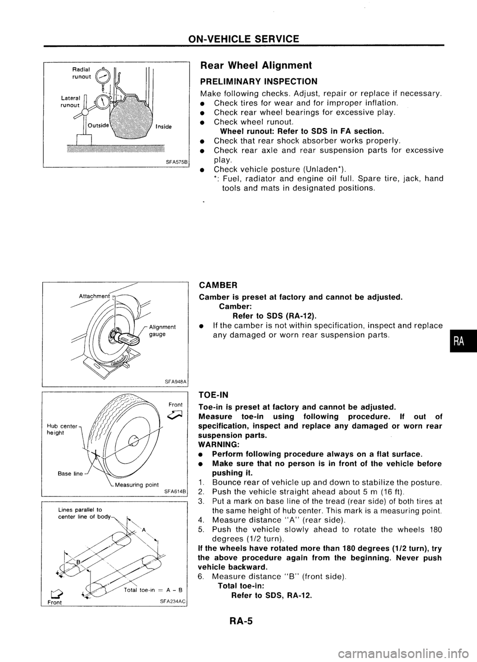
Rear Wheel Alignment
PRELIMINARY INSPECTION
Make following checks.Adjust,repairorreplace ifnecessary.
• Check tiresforwear andforimproper inflation.
• Check rearwheel bearings forexcessive play.
• Check wheelrunout.
Wheel runout: RefertoSOS inFA section.
• Check thatrear shock absorber worksproperly.
• Check rearaxleandrear suspension partsforexcessive
SFA575B
play.
• Check vehicle posture (Unladen*).
*: Fuel, radiator andengine oilfull. Spare tire,jack, hand
tools andmats indesignated positions.
•
CAMBER
Camber ispreset atfactory andcannot beadjusted.
Camber: Refer toSOS (RA-12).
• Ifthe camber isnot within specification, inspectandreplace
any damaged orworn rearsuspension parts.
TOE-IN
Toe-in ispreset atfactory andcannot beadjusted.
Measure toe-inusingfollowing procedure. Ifout of
specification, inspectandreplace anydamaged orworn rear
suspension parts.
WARNING:
• Perform following procedure alwaysonaflat surface.
• Make surethatnoperson isin front ofthe vehicle before
pushing it.
1. Bounce rearofvehicle upand down tostabilize theposture.
2. Push thevehicle straight aheadabout5m (16
ft).
3. Putamark onbase lineofthe tread (rearside) ofboth tires at
the same height ofhub center. Thismark isameasuring point.
4. Measure distance"A"(rear side).
5. Push thevehicle slowlyaheadtorotate thewheels 180
degrees (1/2turn).
If the wheels haverotated morethan180degrees (1/2turn), try
the above procedure againfromthebeginning. Neverpush
vehicle backward.
6. Measure distance"B"(front side).
Total toe-in:
Refer toSOS, RA-12.
Front
SFA948A
SFA614B
SFA234AC
Lines
parallel to
center lineofbOdY~
Q
Front
Hub
center
height
RA-5
Page 1620 of 1701
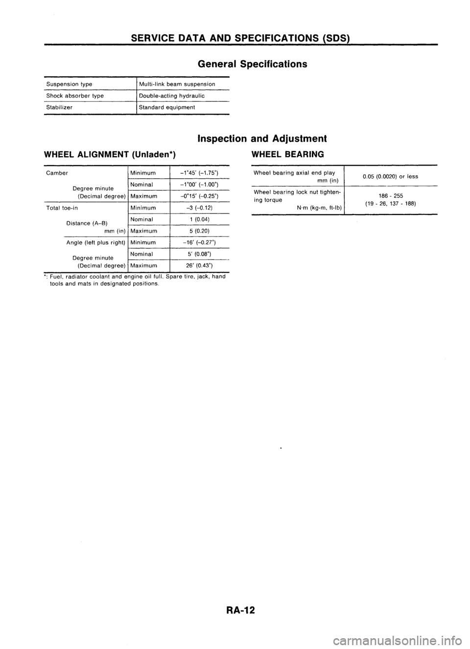
SERVICEDATAANDSPECIFICATIONS (50S)
General Specifications
Suspension type
Shock absorber type
Stabilizer Multi-link
beamsuspension
Double-acting hydraulic
Standard equipment
WHEEL ALIGNMENT (Unladen*) Inspection
andAdjustment
WHEEL BEARING
Camber Minimum-1'45'
(-1.75')
Degree minute Nominal
-1'00'
(-1.00')
(Decimal degree) Maximum -0'15'
(-0.25')
Total toe-in Minimum-3
(-0.12)
Distance (A-B) Nominal
1
(0.04)
mm (in) Maximum 5(0.20)
Angle (leftpius right) Minimum -16'(-0.27')
Degree minute Nominal
5'
(0.08')
(Decimal degree)Maximum 26'
(0.43') Wheel
bearing axialendplay
mm (in)
Wheel bearing locknuttighten-
ing torque
N'm(kg-m. ft-lb) 0.05
(0.0020) orless
186 -255
(19 -26, 137 -188)
': Fuel, radiator coolantandengine oilfull. Spare tire.jack, hand
tools andmats indesignated positions.
RA-12