1995 NISSAN ALMERA N15 low beam
[x] Cancel search: low beamPage 447 of 1701
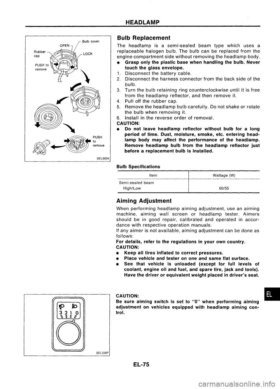
Bulbcover
SEL995K HEADLAMP
Bulb Replacement
The headlamp isasemi-sealed beamtypewhich usesa
replaceable halogenbulb.Thebulb canbereplaced fromthe
engine compartment sidewithout removing theheadlamp body.
• Grasp onlytheplastic basewhen handling thebulb. Never
touch theglass envelope.
1. Disconnect thebattery cable.
2. Disconnect theharness connector fromtheback sideofthe
bulb.
3. Turn thebulb retaining ringcounterclockwise until
it
is free
from theheadlamp reflector,andthen remove it.
4. Pull offthe rubber cap.
5. Remove theheadlamp bulbcarefully. Donot shake orrotate
the bulb when removing it.
6. Install inthe reverse orderofremoval.
CAUTION:
• Do not leave headlamp reflector withoutbulbforalong
period oftime. Dust,moisture, smoke,etc.entering head-
lamp bodymayaffect theperformance ofthe head lamp.
Remove headlamp bulbfrom thehead lamp reflector just
before areplacement bulbisinstalled.
Bulb Specifications
Item
Semi-sealed beam
High/Low Wattage
(W)
60/55
f>
to
3 21 0
~ nOD
o
SEL226PAiming
Adjustment
When performing headlamp aiming adjustment, useanaiming
machine, aimingwallscreen orheadlamp tester.Aimers
should beingood repair, calibrated andoperated inaccor-
dance withrespective operationmanuals.
If any aimer isnot available, aimingadjustment canbedone as
follows:
For details, refertothe regulations inyour owncountry.
CAUTION:
• Keep alltires inflated tocorrect pressures.
• Place vehicle andtester onone and same flatsurface.
• See thatvehicle isunloaded (exceptforfull levels of
coolant, engineoiland fuel, andspare tire,jack andtools).
Have thedriver orequivalent weightplaced indriver's seat.
CAUTION: •
Be sure aiming switchisset to
"0"
when performing aiming
adjustment onvehicles equipped withheadlamp aiming con-
trol.
EL-75
Page 448 of 1701
-
Up and down adjusting screw
, \ ,I/
MEL614DHEADLAMP
Aiming Adjustment (Cont'd)
LOW BEAM
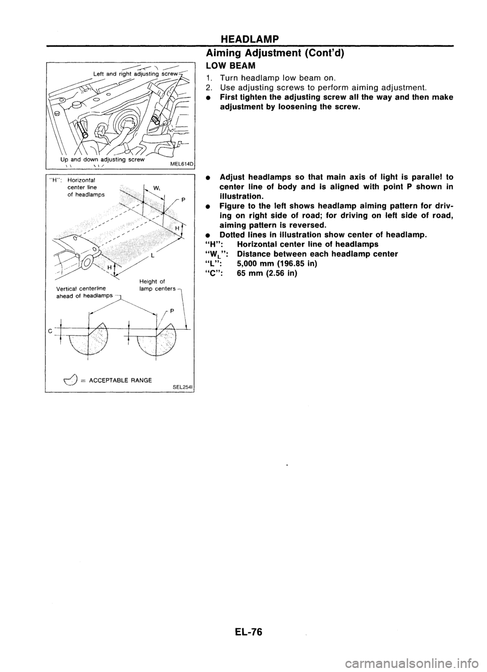
1. Turn headlamp lowbeam on.
2. Use adjusting screwstoperform aimingadjustment.
• First tighten theadjusting screwallthe way andthen make
adjustment byloosening thescrew.
• Adjust headlamps sothat main axisoflight isparallel to
center lineofbody andisaligned withpoint Pshown in
illustration.
• Figure tothe leftshows headlamp aiming pattern fordriv-
ing onright sideofroad; fordriving onleft side ofroad,
aiming pattern isreversed.
• Dotted linesinillustration showcenter ofhead lamp.
"H":
Horizontal centerlineofheadlamps
"W
L":
Distance betweeneachheadlamp center
"l":
5,000mm(196.85 in)
"e":
65mm (2.56 in)
Height of
lamp centers
I
f
P \
/~
Vertical
centerline
ahead ofheadlamps -
"H":
Horizontal
center line
of headlamps
d
=
ACCEPTABLE RANGE
SEL2541
EL-76
Page 473 of 1701
GEL001EXTERIOR
LAMP
Front FogLamp BulbReplacement
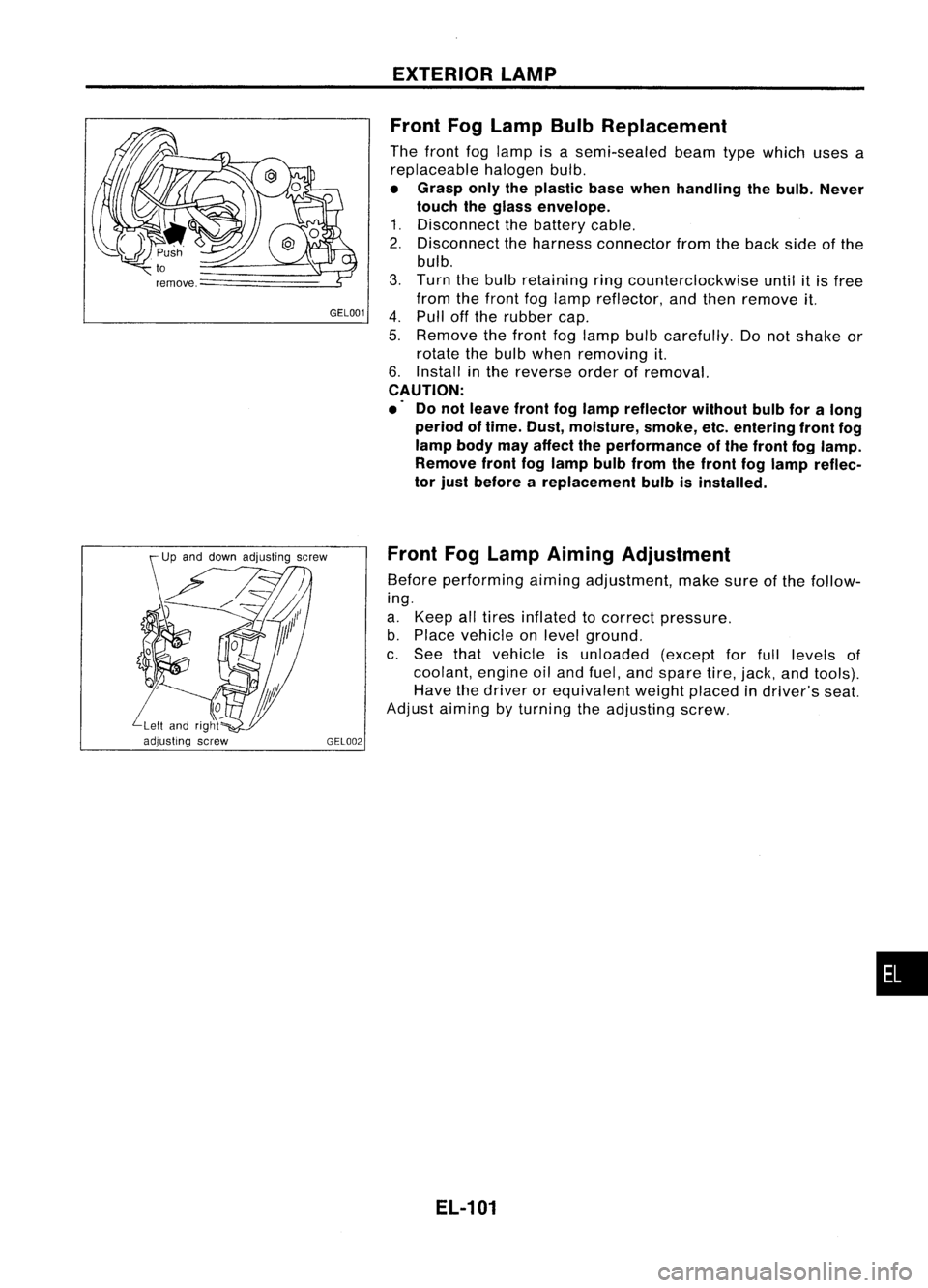
The front foglamp isasemi-sealed beamtypewhich usesa
replaceable halogenbulb.
• Grasp onlytheplastic basewhen handling thebulb. Never
touch theglass envelope.
1. Disconnect thebattery cable.
2. Disconnect theharness connector fromtheback sideofthe
bulb.
3. Turn thebulb retaining ringcounterclockwise untilitis free
from thefront foglamp reflector, andthen remove it.
4. Pull offthe rubber cap.
5. Remove thefront foglamp bulbcarefully. Donot shake or
rotate thebulb when removing it.
6. Install inthe reverse orderofremoval.
CAUTION:
.' Donot leave frontfoglamp reflector withoutbulbforalong
period oftime. Dust, moisture, smoke,etc.entering frontfog
lamp bodymayaffect theperformance ofthe front foglamp.
Remove frontfoglamp bulbfrom thefront foglamp reflec-
tor just before areplacement bulbisinstalled.
Front FogLamp Aiming Adjustment
Before performing aimingadjustment, makesureofthe follow-
ing.
a. Keep alltires inflated tocorrect pressure.
b. Place vehicle onlevel ground.
c. See thatvehicle isunloaded (exceptforfull levels of
coolant, engineoiland fuel, andspare tire,jack, andtools).
Have thedriver orequivalent weightplaced indriver's seat.
Adjust aiming byturning theadjusting screw.
EL-101
•
Page 1281 of 1701

SEM141FA
jPiSIOn healer
SEM877S CYLINDER
BLOCK
CAUTION:
• When installing slidingparts(bearings, pistons,etc.),apply
new engine oiltothe sliding surfaces.
• Place removed partssuchasbearings andbearing capsin
their proper orderanddirection.
• Apply newengine oiltobolt thread andseat surfaces when
tightening thefollowing: Connecting rodbolts andmain
bearing capbolts.
• Donot allow anymagnetic materials tocontact thering gear
teeth offlywheel/drive plate.
Disassembly
PISTON ANDCRANKSHAFT
1. Place engine onawork stand.
2. Remove cylinder head.
Refer to"Removal" in"TIMING CHAIN"(EM-69).
3. Remove oilpan.
Refer to"Removal" in"OIL PAN" (EM-63).
4. Remove timingchain.
Refer to"Removal" in"TIMING CHAIN"(EM-69).
5. Remove pistonswithconnecting rods.
• When disassembling pistonandconnecting rod,remove
snap ringfirst. Then heatpiston to60 to70°C (140to158°F),
or use piston pinpress stand atroom temperature.
6. Remove rearoilseal retainer.
7. Remove bearingbeam,bearing capand crankshaft.
• Before removing bearingcap,measure crankshaft endplay.
• Bolts should beloosened intwo orthree steps.
Loosen innumerical order.
SEM007D
AEM023
Inspection
PISTON ANDPISTON PINCLEARANCE
1. Measure innerdiameter ofpiston pinhole "dp".
Standard diameter"dp":
21.987 -21.999
mm
(0.8656 -0.8661
in)
EM-102
Page 1285 of 1701
#5
#4 ~
~i1
hole #3~~ \)
#2 ~~,
#1~~~ ~~
12 ~~
Engine front~
SEM685D
SEM964
SEM313D CYLINDER
BLOCK
Inspection (Cont'd)
BEARING CLEARANCE
• Use either ofthe following twomethods, however, method
"A" gives morereliable resultsandispreferred.
Method A(Using boregauge
&
micrometer)
Main bearing
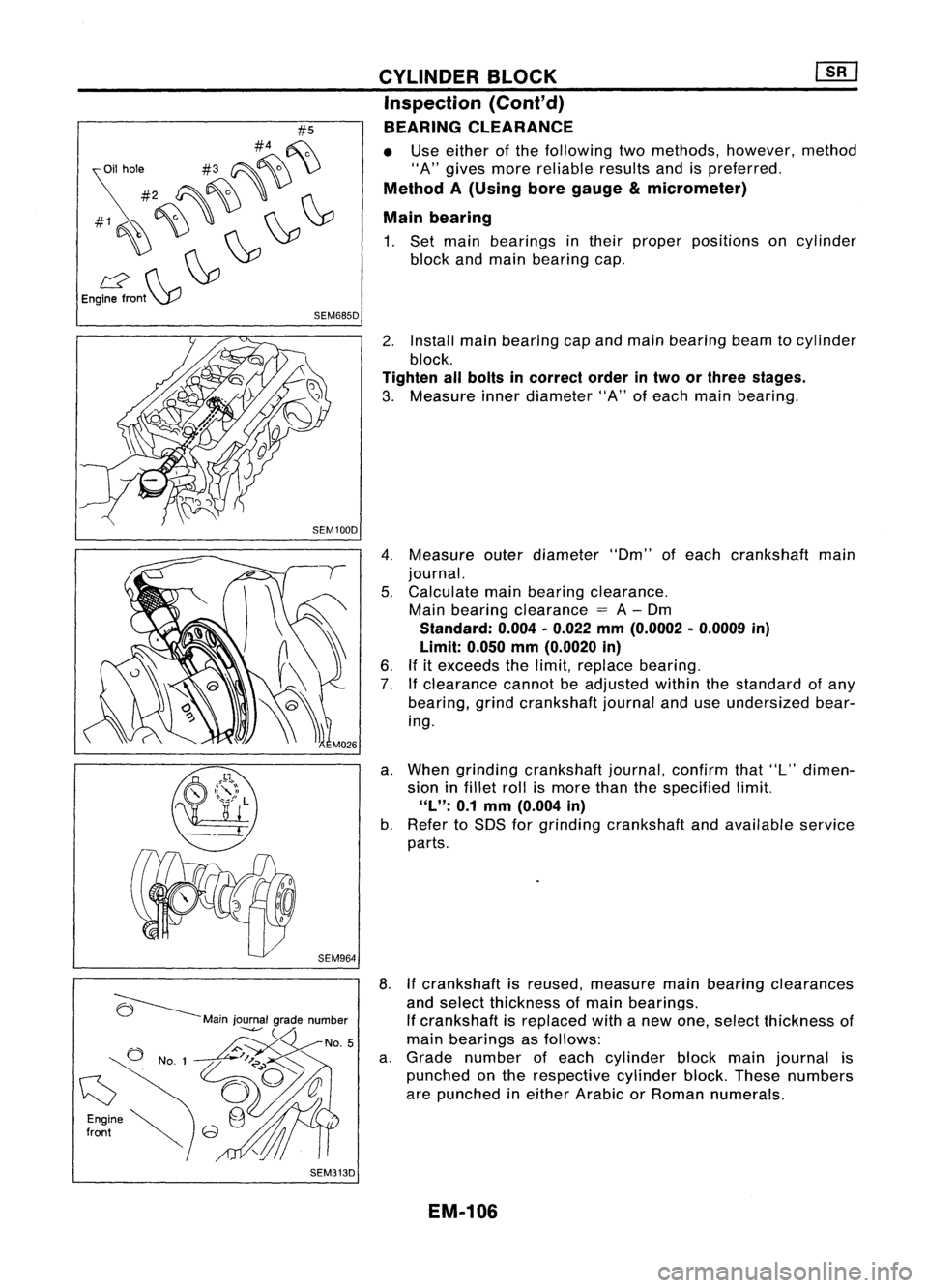
1. Set main bearings intheir proper positions oncylinder
block andmain bearing cap.
2. Install mainbearing capand main bearing beamtocylinder
block.
Tighten allbolts incorrect orderintwo orthree stages.
3. Measure innerdiameter "A"ofeach main bearing.
4. Measure outerdiameter "Om"ofeach crankshaft main
journal.
5. Calculate mainbearing clearance.
Main bearing clearance
=
A-Om
Standard: 0.004•0.022 mm(0.0002 •0.0009 in)
Limit: 0.050mm(0.0020 in)
6. Ifitexceeds thelimit, replace bearing.
7. Ifclearance cannotbeadjusted withinthestandard ofany
bearing, grindcrankshaft journalanduseundersized bear-
ing.
a. When grinding crankshaft journal,confirmthat"L"dimen-
sion infillet rollismore thanthespecified limit.
"L":
0.1mm (0.004 in)
b. Refer toSOS forgrinding crankshaft andavailable service
parts.
8. Ifcrankshaft isreused, measure mainbearing clearances
and select thickness ofmain bearings.
If crankshaft isreplaced withanew one, select thickness of
main bearings asfollows:
a. Grade number ofeach cylinder blockmainjournal is
punched onthe respective cylinderblock.These numbers
are punched ineither Arabic orRoman numerals.
EM-106
Page 1617 of 1701
SRA696A
SRA697A
S
Control rod
Lateral link
~H";""I"
ITorsion
beam
SRA698AREAR
SUSPENSION
Removal andInstallation
CAUTION:
• Before removing therear suspension assembly,disconnect
the ABS wheel sensor fromtheassembly. Failuretodo so
may result indamage tothe sensor wiresandthesensor
becoming inoperative.
• Remove suspension assembly.
1. Disconnect brakehydraulic linesandparking brakecableat
toggle lever.(Models withdrum brakes.)
• Drain brake fluidbefore disconnecting brakelines.
2. Disconnect parkingbrakecablefromcaliper andremove
brake caliper androtor. (Models withdiscbrakes.)
Suspend caliperassembly withwire soasnot tostretch brake
hose.
Be careful nottodepress brakepedal, orpiston willpop out.
Make surebrake hoseisnot twisted.
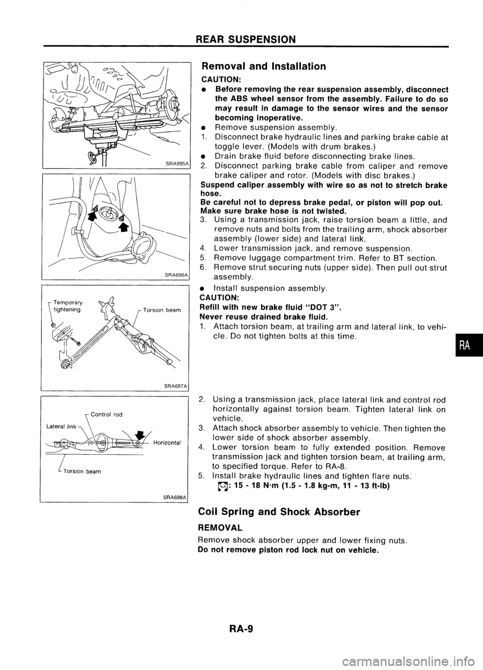
3. Using atransmission jack,raise torsion beamalittle, and
remove nutsandbolts fromthetrailing arm,shock absorber
assembly (lowerside)andlateral link.
4. Lower transmission jack,andremove suspension.
5. Remove luggagecompartment trim.Refer toBT section.
6. Remove strutsecuring nuts(upper side).Thenpulloutstrut
assembly.
• Install suspension assembly.
CAUTION: Refill withnewbrake fluid"DOT
3".
Never reusedrained brakefluid.
1. Attach torsion beam,attrailing armandlateral link,tovehi-
cle. Donot tighten boltsatthis time.
2. Using atransmission jack,place lateral linkand control rod
horizontally againsttorsionbeam.Tighten laterallinkon
vehicle.
3. Attach shockabsorber assembly tovehicle. Thentighten the
lower sideofshock absorber assembly.
4. Lower torsion beamtofully extended position.Remove
transmission jackandtighten torsion beam,attrailing arm,
to specified torque.RefertoRA-8.
5. Install brakehydraulic linesandtighten flarenuts.
~: 15-18 N'm (1.5.1.8 kg-m,11-13 ft-Ib)
Coil Spring andShock Absorber
REMOVAL
Remove shockabsorber upperandlower fixing nuts.
Do not remove pistonrodlock nutonvehicle.
RA-9
•
Page 1643 of 1701
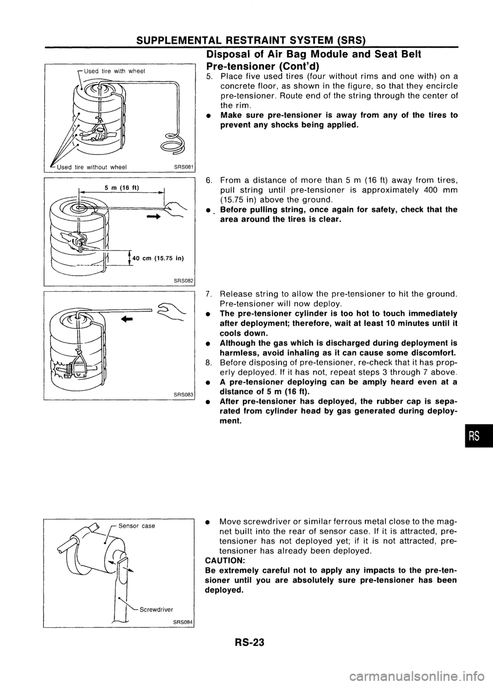
6.From adistance ofmore than5m (16
ft)
away fromtires,
pull string untilpre-tensioner isapproximately 400mm
(15.75 in)above theground.
• Before pulling string,onceagain forsafety, checkthatthe
area around thetires isclear.
SRS081
SUPPLEMENTAL
RESTRAINTSYSTEM(SRS)
Disposal ofAir Bag Module andSeat Belt
Pre-tensioner (Cont'd)
5. Place fiveused tires(four without rimsandonewith) ona
concrete floor,asshown inthe figure, sothat they encircle
pre-tensioner. Routeendofthe string through thecenter of
the rim.
• Make surepre-tensioner isaway fromanyofthe tires to
prevent anyshocks beingapplied.
40
em
(15.75
in)
5
m
(16
ft)
SRS082
SRS083
7.
Release stringtoallow thepre-tensioner tohit the ground.
Pre-tensioner willnow deploy.
• The pre-tensioner cylinderistoo hottotouch immediately
after deployment; therefore,waitatleast 10minutes untilit
cools down.
• Although thegas which isdischarged duringdeployment is
harmless, avoidinhaling asitcan cause somediscomfort.
8. Before disposing ofpre-tensioner, re-checkthatithas prop-
erly deployed. Ifithas not,repeat steps3through 7above.
• Apre-tensioner deployingcanbeamply heardevenata
distance of5m (16 ft).
• After pre-tensioner hasdeployed, therubber capissepa-
rated fromcylinder headbygas generated duringdeploy-
ment.
•
• Move screwdriver orsimilar ferrous metalclosetothe mag-
net built intotherear ofsensor case.Ifitis attracted, pre-
tensioner hasnotdeployed yet;ifit is not attracted, pre-
tensioner hasalready beendeployed.
CAUTION:
Be extremely carefulnottoapply anyimpacts tothe pre-ten-
sioner untilyouareabsolutely surepre-tensioner hasbeen
deployed.
RS-23