Page 140 of 1701
KV38105710
Transmission
case
NAT033
Reduction
pinion
gear
SAT332DA
D
SAT333DA ASSEMBLY
Adjustment 1(Cont'd)
9. Remove converter housingfromtransmission case.
10. Remove finaldrive assembly fromtransmission case.
11. Remove differential sidebearing outerracefrom transmis-
sion case.
12. Reinstall differential sidebearing outerraceandshim(s)
selected fromSDStable ontransmission case.
13. Reinstall converter housingontransmission caseand
tighten transmission casefixing boltstothe specified
torque.
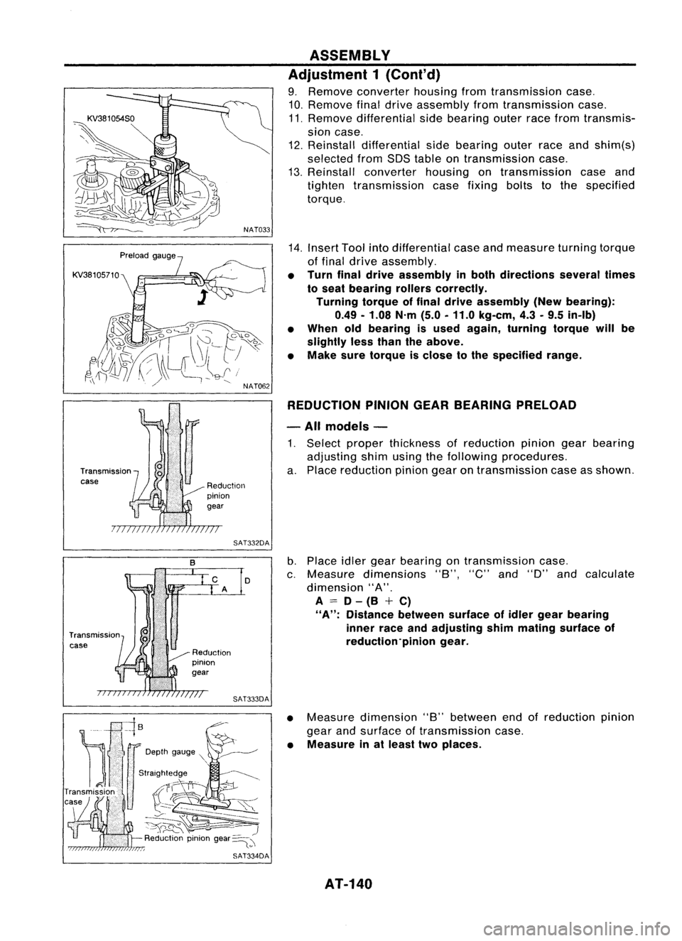
14. Insert Toolintodifferential caseandmeasure turningtorque
of final drive assembly.
• Turn finaldrive assembly inboth directions severaltimes
to seat bearing rollerscorrectly.
Turning torqueoffinal drive assembly (Newbearing):
0.49 -1.08 N'm(5.0-11.0 kg-em, 4.3-9.5 in-Ib)
• When oldbearing isused again, turning torquewillbe
slightly lessthan theabove.
• Make suretorque isclose tothe specified range.
REDUCTION PINIONGEARBEARING PRELOAD
- All models -
1. Select proper thickness ofreduction piniongearbearing
adjusting shimusing thefollowing procedures.
a. Place reduction piniongearontransmission caseasshown.
b. Place idlergear bearing ontransmission case.
c. Measure dimensions "8","C"and"D" andcalculate
dimension "A".
A
=
D-(8 +C)
"A":
Distance betweensurfaceofidler gear bearing
inner raceandadjusting shimmating surface of
reduction'pinion gear.
• Measure dimension "8"between endofreduction pinion
gear andsurface oftransmission case.
• Measure inat least twoplaces.
AT-140
Page 284 of 1701
SBR435BMASTER
CYLINDER
Assembly (Cont'd)
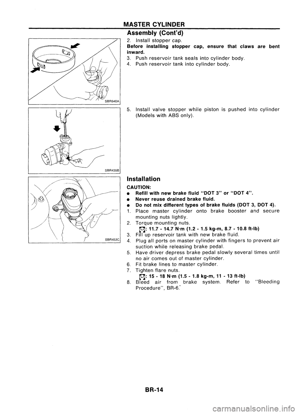
2. Install stopper cap.
Before installing stoppercap,ensure thatclaws arebent
inward.
3. Push reservoir tankseals intocylinder body.
4. Push reservoir tankintocylinder body.
5. Install valvestopper whilepiston ispushed intocylinder
(Models withABS only).
Installation
CAUTION:
• Refill withnewbrake fluid"DOT 3"or"DOT 4".
• Never reusedrained brakefluid.
• Donot mix different typesofbrake fluids(DOT3,DOT 4).
1. Place master cylinder ontobrake booster andsecure
mounting nutslightly.
2. Torque mounting nuts.
~: 11.7 -14.7 N'm(1.2-1.5 kg-m, 8.7-10.8 ft-Ib)
3. Fillupreservoir tankwith newbrake fluid.
4. Plug allports onmaster cylinder withfingers toprevent air
suction whilereleasing brakepedal.
5. Have driver depress brakepedalslowly several timesuntil
no air comes outofmaster cylinder.
6. Fitbrake linestomaster cylinder.
7. Tighten flarenuts.
~: 15-18 N'm (1.5-1.8 kg-m, 11-13 ft-Ib)
8. Bleed airfrom brake system. Referto"Bleeding
Procedure", BR-6."
BR-14
Page 285 of 1701
OKNGBRAKE
BOOSTER
On-vehicle Service
OPERATING CHECK
• Depress brakepedalseveral timeswithengine off.After
exhausting vacuum,makesurethere isno change inpedal
stroke.
• Depress brakepedal, thenstart engine. Ifpedal goesdown
slightly, operation isnormal.
AIRTIGHT CHECK
• Start engine, andstop itafter oneortwo minutes. Depress
SBR002A
brakepedalseveral timesslowly. Booster isairtight ifpedal
stroke isless each time.
• Depress brakepedalwhileengine isrunning, andstop
engine withpedal depressed. Thepedal stroke should not
change afterholding pedaldownfor
30seconds.
SBR365AA Removal
CAUTION:
• Becareful nottosplash brakefluidonpainted areas;itmay
cause paintdamage. Ifbrake fluidissplashed onpainted
areas, washitaway withwater immediately.
• Be careful nottodeform orbend brake pipes, during
removal ofbooster.
SEC.
465.470
BR-15Gasket
~ :N.m (kg-m. ft-Ib)
SBR223BB
•
Page 286 of 1701
Approx.125mm (4.92 In) BRAKE
BOOSTER
Inspection
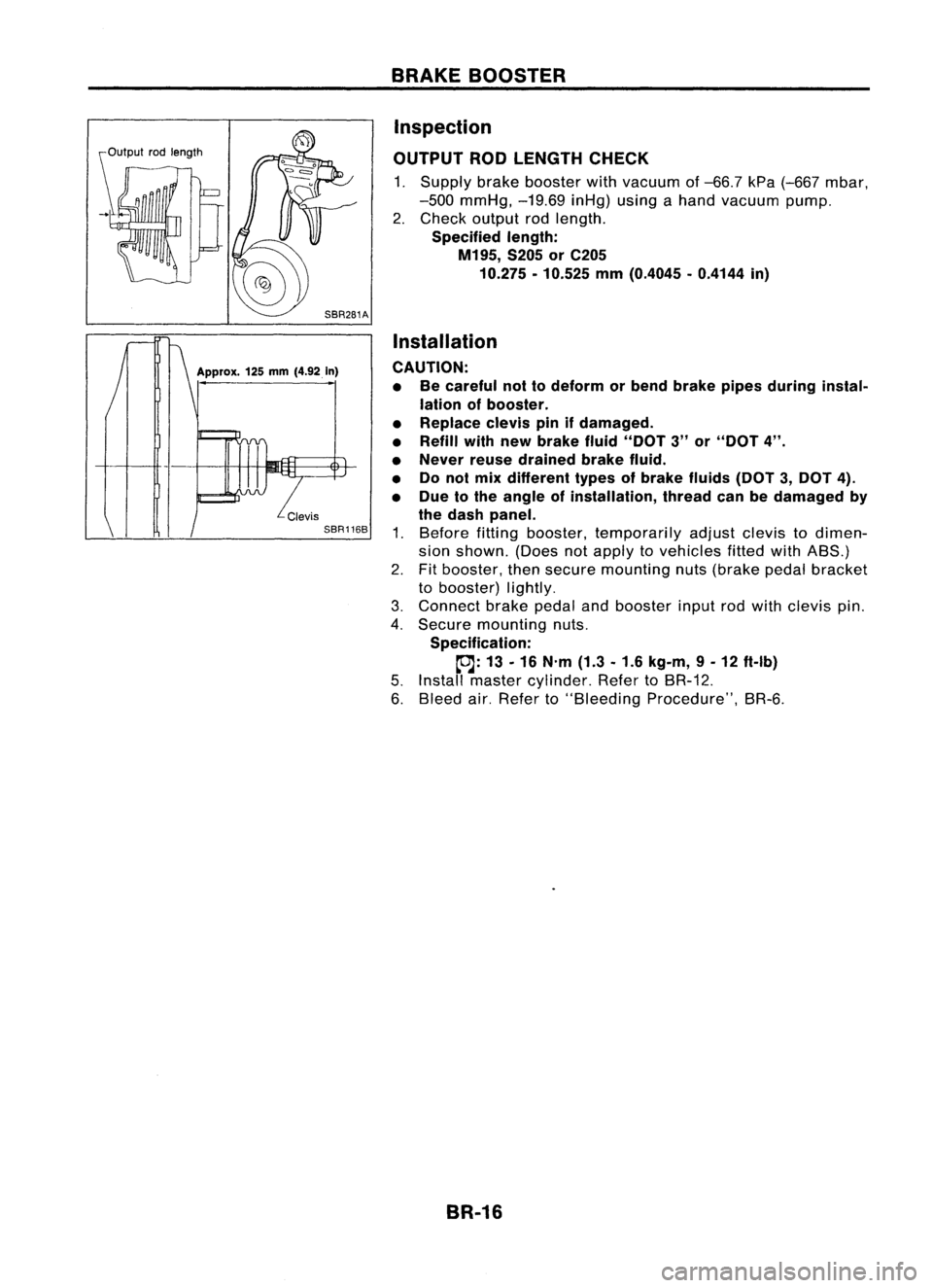
OUTPUT RODLENGTH CHECK
1. Supply brakebooster withvacuum of-66.7 kPa(-667 mbar,
-500 mmHg, -19.69inHg)usingahand vacuum pump.
2. Check output rodlength.
Specified length:
M195, S205orC205
10.275 -10.525 mm(0.4045 -0.4144 in)
Installation
CAUTION: • Becareful nottodeform orbend brake pipesduring instal-
lation ofbooster.
• Replace clevispinifdamaged.
• Refill withnewbrake fluid"DOT 3"or"DOT 4".
• Never reusedrained brakefluid.
• Donol mix different typesofbrake fluids(DOT3,DOT 4).
• Due tothe angle ofinstallation, threadcanbedamaged by
the dash panel.
1. Before fittingbooster, temporarily adjustclevistodimen-
sion shown. (Doesnotapply tovehicles fittedwithABS.)
2. Fitbooster, thensecure mounting nuts(brake pedalbracket
to booster) lightly.
3. Connect brakepedalandbooster inputrodwith clevis pin.
4. Secure mounting nuts.
Specification:
~: 13-16 N'm (1.3-1.6 kg-m, 9-12 ft-Ib)
5. Install master cylinder. RefertoBR-12.
6. Bleed air.Refer to"Bleeding Procedure", BR-6.
BR-16
Page 308 of 1701
ANTI-LOCKBRAKESYSTEM
Purpose
The Anti-Lock BrakeSystem (ABS)consists ofelectronic andhydraulic components. Itallows forcon-
trol ofbraking forcesothat locking ofthe wheels canbeavoided.
The ABS:
1) Improves propertracking performance throughsteering wheeloperation.
2) Eases obstacles tobe avoided throughsteering wheeloperation.
3) Improves vehiclestability bypreventing flatspins.
Operation
• When thevehicle speedisless than 10km/h (6MPH) thissystem doesnotwork.
• The Anti-Lock BrakeSystem (ABS)hasself-test capabilities. Thesystem turnsonthe ABS warning
light for1second afterturning theignition switchON.The system performs anothertestthefirst time
the vehicle reaches 6km/h (4MPH). Amechanical noisemaybeheard asthe ABS performs aself-
test. This isanormal partofthe self-test feature.Ifa malfunction isfound during thischeck, theABS
warning lightwillcome on.
• During ABSoperation, amechanical noisemaybeheard. Thisisanormal condition.
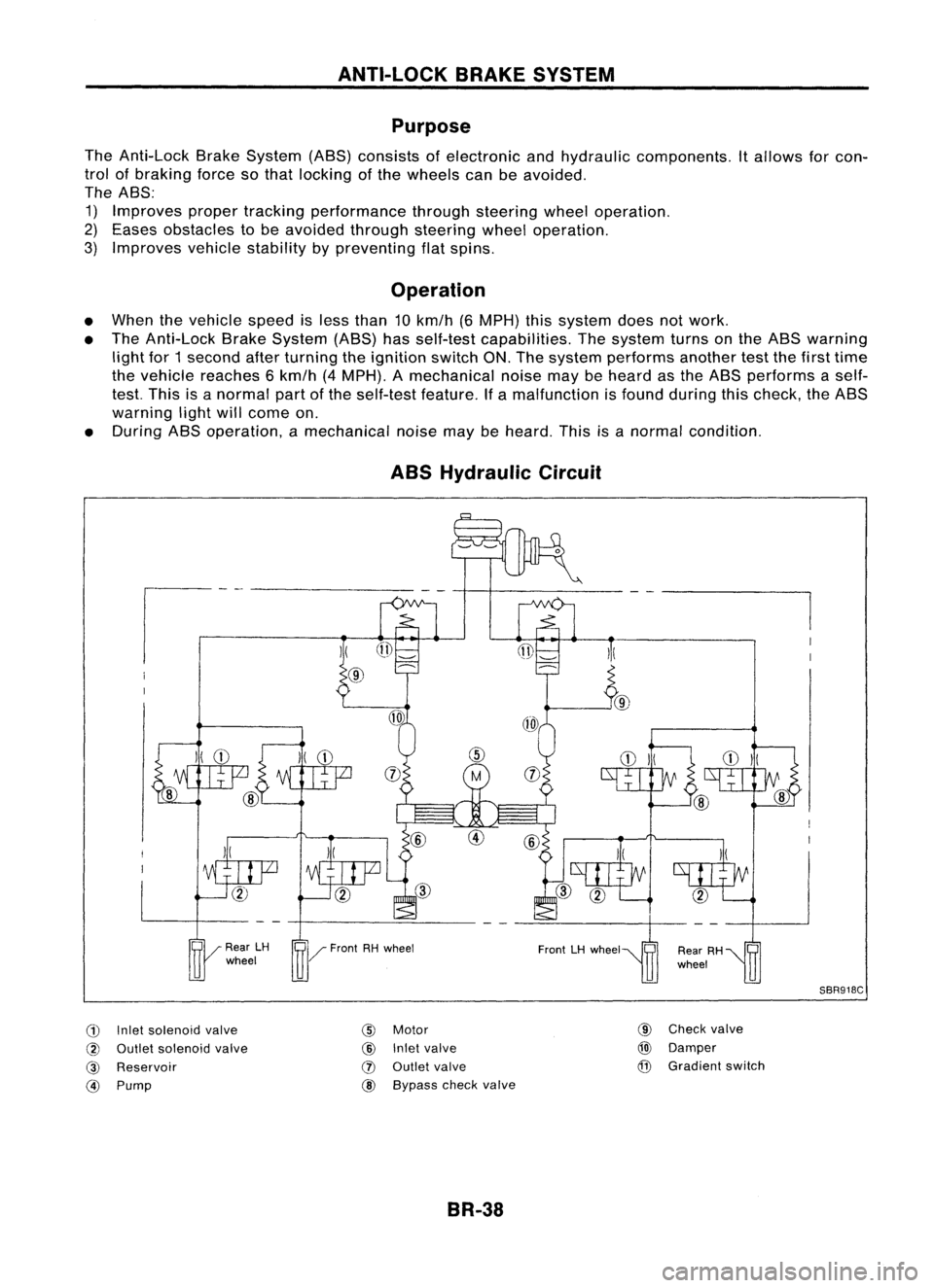
ABS Hydraulic Circuit
G)
Inletsolenoid valve
@
Outlet solenoid valve
@
Reservoir
@)
Pump
)(
@
@
Motor
@
Inletvalve
(J)
Outlet valve
@ Bypass checkvalve
BR-38 @
Check valve
@)
Damper
@
Gradient switch
SBR918C
Page 309 of 1701

ANTI-LOCKBRAKESYSTEM
System Components
Dual proportioning
valve
Rearwheel sensors
For LHD models, controlunit
is located onthe opposite side.
SBR048DB
Control unit
s::';o~'~W.
r
Magnetic flux~ _~-Coil
I .I
Tooth~ Sensorrotor
/ ~m~f onetooth
v:~-- System
Description
SENSOR
The sensor unitconsists ofagear-shaped sensorrotoranda
sensor element. Theelement contains abar magnet around
which acoil iswound. Thesensor isinstalled onthe back side
of the brake rotor.Sine-wave currentisgenerated bythe sen-
sor asthe wheel rotates. Thefrequency andvoltage increase(s) •
as the rotating speedincreases. :•
V: Induced electromotive force
SBR124B
SBR049DA CONTROL
UNIT
The control unitcomputes thewheel rotating speedbythe sig-
nal current sentfrom thesensor. Thenitsupplies aDC current
to the actuator solenoid valve.Italso controls ON-OFFopera-
tion ofthe valve relayandmotor relay.Ifany electrical malfunc-
tion should bedetected inthe system, thecontrol unitcauses
the warning lamptolight up.Inthis condition, theASS willbe
deactivated bythe control unit,andthevehicle's brakesystem
reverts tonormal operation.
BR-39
Page 338 of 1701
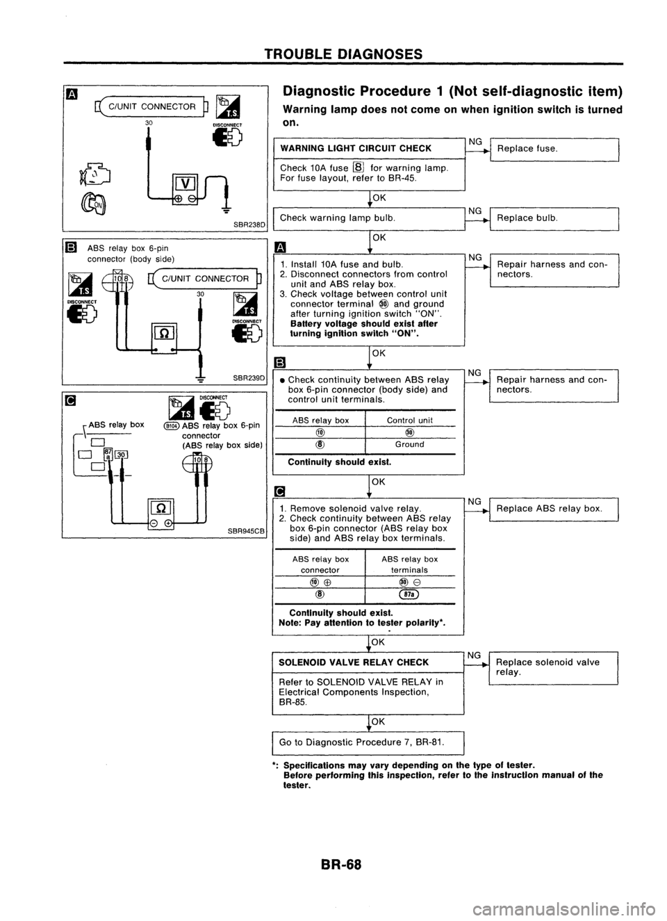
TROUBLEDIAGNOSES
Diagnostic Procedure1(Not self-diagnostic item)
Warning lampdoes notcome onwhen ignition switchisturned
on.
c(
C/UNIT CONNECTOR
30
p~
15
SBR238D WARNING
LIGHTCIRCUIT CHECK
Check 10Afuse ~forwarning lamp.
For fuse layout, refertoSR-4S.
OK
Check warning lampbulb.
NG
NG
Replace
fuse.
Replace bulb.
Ii) ASSrelay box6-pin
connector (bodyside)
~ 108
c(
C/UNIT CONNECTOR
P
I...a1
30~
15
l.41
Iv
OK
1. Install 10Afuse andbulb.
2. Disconnect connectors fromcontrol
unit and ASS relay box.
3. Check voltage between controlunit
connector terminal
@
and ground
after turning ignition switch"ON".
Battery voltage shouldexistafter
turning ignition switch
"ON".
OK
NG
Repair harness andcon-
nectors.
OK
Continuity
shouldexist.
•
Check continuity betweenASSrelay
box 6-pin connector (bodyside)and
control unitterminals.
\ ASS relay box
f~~~_
SBR239D
~i5
@ID
ASS relay box6-pin
connector (ASS relayboxside)
108
ASS
relay box
@)
Control
unit
@
Ground
NG
Repair harness andcon-
nectors.
1. Remove solenoid valverelay.
2. Check continuity betweenASSrelay
SBR945CB
box6-pin connector (ASSrelaybox
side) andASS relay boxterminals.
ASS relay box ASS
relay box
connector terminals
@)\B
@e
@
Continuity shouldexist.
Note: Payattention totester polarity",
OK
SOLENOID VALVERELAYCHECK
Refer toSOLENOID VALVERELAY in
Electrical Components Inspection,
BR-8S.
OK
Go toDiagnostic Procedure7,BR-81.
NG
NG
Replace
ABSrelay box.
Replace solenoid valve
relay.
": Specifications mayvary depending onthe type oftester.
Before performing thisinspection, refertothe instrucllon manualofthe
tester.
BR-68
Page 370 of 1701
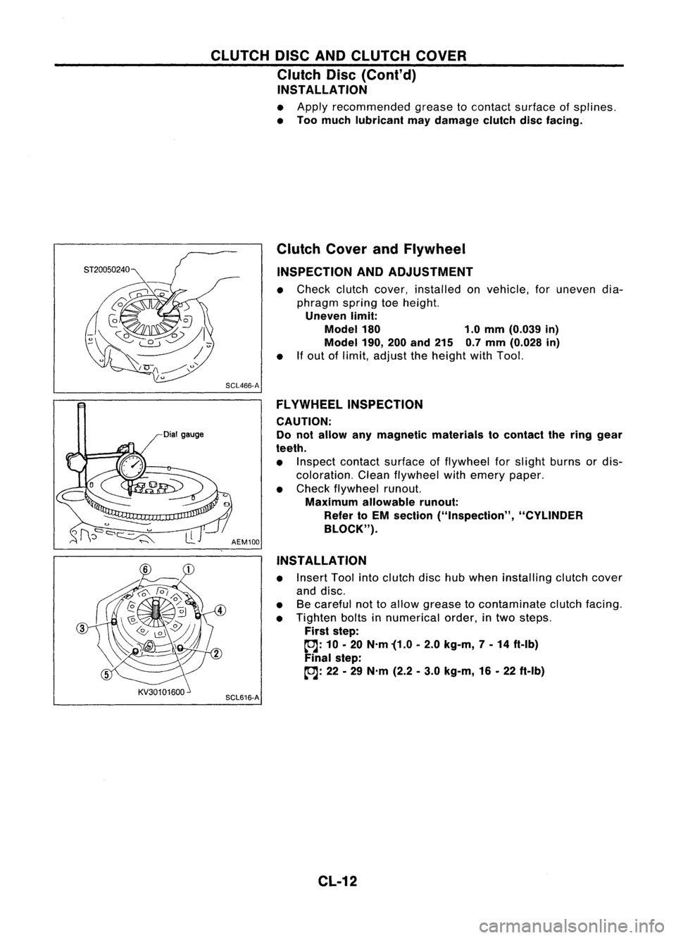
CLUTCHDISCANDCLUTCH COVER
Clutch Disc(Cont'd)
INSTALLATION
• Apply recommended greasetocontact surface ofsplines.
• Too much lubricant maydamage clutchdiscfacing.
Dial gauge Clutch
CoverandFlywheel
INSPECTION ANDADJUSTMENT
• Check clutchcover, installed onvehicle, foruneven dia-
phragm springtoeheight.
Uneven limit:
Model 180 1.0mm (0.039 in)
Model 190,
200and 215 0.7mm (0.028 in)
• Ifout oflimit, adjust theheight withTool.
SCL466-A FLYWHEEL INSPECTION
CAUTION:
Do not allow anymagnetic materials tocontact thering gear
teeth.
• Inspect contact surface offlywheel forslight burns ordis-
coloration. Cleanflywheel withemery paper.
• Check flywheel runout.
Maximum allowable runout:
Refer toEM section ("Inspection", "CYLINDER
BLOCK").
AEM100
INSTALLATION
• Insert Toolintoclutch dischubwhen installing clutchcover
and disc.
• Becareful nottoallow grease tocontaminate clutchfacing.
• Tighten boltsinnumerical order,intwo steps.
First step:
~: 10•20 N'm '(1.0 •2.0 kg-m, 7-14 ft-Ib)
Final step:
~: 22•29 N'm (2.2•3.0 kg-m, 16•22 ft-Ib)
SCL616-A
CL-12