Page 465 of 1701
HATCHBACK MODELS EXTERIOR
LAMP
Stop Lamp/Wiring Diagram-STOP/L -
(Cant' d)
•
Refer
tolast page
(Foldout page).
l
i
TAIL STOP TAILSTOP
~REAR ~REAR
a
E~~~I~~ nON
a
E~~~I~~ nON
I
(OUTER) ~
I
(OUTER) ~
_. 1.
I
f.
a a
--- ......
~
"="
(1):
LHDmodels
(8):
RHOmode 1s
@:
Models withhigh-mounted
stop lamponrear window
~: Models withhigh-mounted
stop lampinrear airspoiler
~t1 ...
(1)
R/Y,
(8)
RIL
fEi)!
I
Ill)
@W
m
(0102)
45678 W
ill
W
{+
*1
To
EL-TAIL/L ..R/L EL-STOP/L-02
FUSE
BLOCK RefertoEL-POWER.
(J/B)
DEPRESSED STOPLAMP
SWITCH
~
~~
L.iJ.gJ
a
RELEASED
~
PIL
•
O~P/L~P/L~
~ ~
PIL
0-.
aJ
i ~
I
JUNCTION LP'L
BOX
NO.2
c!J~
(~g~~~CTORS) ~
@W
PIL
~@:(1)
I
P/L
t
P/L
eb@)
~I
1l\.QJ1
(@
1
HIGH-
P/L MOUNTED
STOP LAMP
~ <01OB):
@
B ~:~
I
.- a~ a
I
(ij25)
a
---
(0105)
~~@
5 6
TIIV01112
W
m
([HOB)
IJ:m
aR
~~
WEJ GY
~@)@
~ w'
W
HEL034
EL-93
Page 479 of 1701
EXTERIORLAMP
Turn Signal andHazard Warning Lamps/Wiring
Diagram -TURN-
LHD MODELS
EL-TURN-01
___ RIG.
ToEL-ILL
RIG
m
•
HAZARD
ILL SWITCH
~
Refer tolast page
(Foldout page).
-G/B~
- G/Y
-@>
To
EL-TURN
_ G/Y ~
-03
-G/B~
- G/Y -f>
Next page
- G/Y~}
_ G/B ~
Next
~ page
.- B~
~
B
c:I:Q]]
(E110)
~W
R
FUSE
RefertoEL-POWER.
BLOCK
(JIB)
~
~ ~
G/B G/Y
12';1 12~1
2~
G/B
2~
G/Y
2~
G/Y
2~
G/B
2~
G/Y
1
2•3
1 1
2•4
1
JUNCTION BOX
NO.2 (JOINT
G/B G/Y
CONNECTORS)
.
.
~
G/B
CBID
G/Y
IriJ~----~$1
___ t.GI" ~GIV,
------'.
F1i21~
'"TIT
B
TURN
SIGNAL
LAMP
SWITCH L
WID
~
LG
t
JUNCTION BOXNO.2
~• I
(JOINT CONNECTORS)
25 ~
2~ LG -,
LG
12~1
CBID~
LGt ml~1
IFtiI
LG
OCT COMBINATION
I
FLASHER
UNIT LG
@)
m
GROUND
Ibj:!J
8
G/R
ffl
POWER
m
11f!]~
54213 W
HEL046
EL-107
Page 492 of 1701
INTERIORLAMP
Illumination/Wiring Diagram-ILL -
(Coni' d)
JUNCTION
BOX NO.2
(JOINT
CONNECTORS)
~:
JOINT
CONNECTOR-4
~:
Next
page
RIG
~ HEADLAMP
~6 WIPER AND
WASHER
SWITCH (ILLUMI-
II 7 II NATION)
L:j='
(856):
B
EL-ILL-05
: LHDmode 1s
:
RHDmodels
Models withdaytime
light system
*9 ...
13
@
3
,
1*.91
RIG
RIG
II!'I
HAZARD
SWITCH
(ILLUMI-
NATION)
~~ B
FUSE
BLOCK
(JIB)
@
IN.BI
RIG
Ii!9TI
~
RIG
t
~o
I
RIG
;2
GLOVE
BOX LAMP
~
l!4Jl
RIW
rn
IN.BI
RIG
I
RIG
REAR WINDOW
i~i
DEFOGGER
SWITCH (ILLUMINA TION)
~ ~
B
Preceding
page
~E -
ILL-02
RIG•
CLOSED GLOVE
BOX LAMP
OPEN SWITCH
~
B BB
LL
m
I1~_I;
JOINT
(
CONNECTOR- 3
_ Next~:
K page JOINT
CONNECTOR-4
---------------------' ~:
~~ ~@
[Q]~
1Irn','1Il~
alll@~
~ W
W
[IIg]
BR54213 W45231 BR
Refer
tolast page
(Foldout page).
rIIII:ITITillTI ~:
rIIII:ITITillTI ~:
~~ ~P
HEL057
EL-120
Page 494 of 1701
INTERIORLAMP
Interior, Spot,Trunk RoomandLuggage Room
Lamps/Wiring Diagram-INT/L -
LHD MODELS
EL-INT/L-01
FUSE BLOCK
(JIB)
RefertoEL-POWER.
~
@)
@:
Sedanmodels
@:
Hatchback modeIs
@:
Models withsunroof
@:
Models without sunroof
IIT.311
IN;31
RIB RIB
@@)
I
•
RIB
1II1}
RIB
0
I
O~
,
t
t
RIB
i~iLUGGAGE
RIB
RIB
RIB ROOM
m m
1~lrnu~
LAMP
~~
ROOM INTERIOR
LAMP R SPOTLAMP
lbi=Jl~
c!J@}
LAMP
ONOFF
aID:@
1bi=Jl@Q!)
ON
<:BID:
@)
......
R R
OFF.....--
DOOR
I
m
~~
R
LUGGAGE
$@
OPENROOM
B
CBD
=
R/W
LAMP
(ill)
SWITCH
IQP~~i~--------~qpl
R
CLOSED
@llID
c!J
B
R/W
~
rn(!)
JLNCTION
TRUNK
ROOM B
JOINTBOX
No.2
LAMP
•
CONNECTOR-1
(JOINT
SWITCH
•
CONNECTORS)
CLOSED
c::ID
•
~
B
~
m@W
~@)
B
R/W
I
B
I
r.
•
I
I
.
B BB B
B
R/W~Next
-!- -!--!-
-!-
-!-
page
<:ITID
(ill)
(Ql05)
~
@
~~
~CID
~W
wCBID(@@
rn::g]
W'W'W
~~~
~ W
I
W
I:illliTI]
@
~W
fHiI'
II~@W
4567B W
rh-f:l@
~ B
n.o-r:l@llID
LUQ.LgJ
B
Refer
tolast page
(Foldout page).
ITIillIITillIII
~BR
EL-122 HEL061
Page 526 of 1701
WARNINGLAMPSANDBUZZER
Warning Buzzer/Wiring Diagram-BUZZER -
LHD MODELS
EL-BUZZER-01
DOOR
SWITCH
DRIVER'S
SIDE
(]ID
OPEN
Refer
to
EL-POWER.
CLOSED
IJ:i=n
B
•
f.
B B
~ ~
@ll)@
FUSE
BLOCK
(JIB)
~
m
IN~41
@:
Withdaytime lightsystem
G1@:WithoutdaytimelightsYstem
*1".@B/R @W
,
G *2...
@
RIL @W/R
•
~ *3".@R/B @R/Y
1I1DI •
IGN WARNING
SW BUZZER
RR FOG DOORUNIT
SW SW(DR)
@
lbjdJ ~
PU/R R
[ttl ']'t4IJUNCTION
BOX NO.2
(JOINT
CONNECTORS)
~------1I~41
PU/R
t
~@)
m
REAR
[jJ
(]V
IND FOG R
LAMP ~
SWITCH II1II
~
OFF
7.5A
1431
B/R
rm
TAIL/L FUSE
I!JjJJ
*2
I
O~ DL W/R
[iJt~:1
R/Y
t
I_-.I~o
tt
RIB
Ii1'on
TAILIL
OUTPUT
RIL
will
TAILIL
SW
\bj::tl
B
rn~
I
JOINT
CONNECTOR-3
I
lU ....,
DAYTIME
=jF
I
LIGHT B
UNIT BB
@ ~~
I..-.--
---J~~
I
BATTERY
I
•
~-17-5A-~'
10.
m
1361
W B/R P
!
I.-",
1$1
~~1)
*1 P
will
L
LIGHTING
SWITCH
~
~~
~BR
IIITIillIIITIIT
@
~BR
~~@)
56j8191OU12 W
r1TmCW
TIT'
B
Refer
tolast page
(Foldout page).
(BID ~
•
~ (106)
•
~~
~GY
HEL083
EL-154
Page 604 of 1701

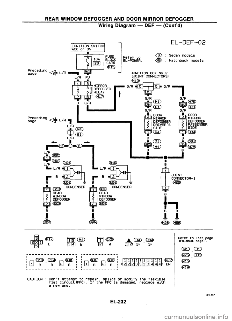
REARWINDOW DEFOGGER ANDDOOR MIRROR DEFOGGER
Wiring Diagram -DEF -(Cont'd)
JUNCTION BOXNo.2
(JOINT CONNECTORS)
G/R?G/R-'
EL-DEF-02
Sedan models
Hatchback models
@:
@:
G/R
IUT\
G/RIG=7c:\
~\.Mi.J ~~
1~1
([D
I~l
@)
G/R G/R
(J)
~RAOA
m~~~
DEFOGGER
DEFOGGER
DRIVER'S PASSENGER
SIDE SIDE
ClJC@ ClJ@)
B B
IrtJl ~~~ ~ 1$1~~~
B B
____ I&__
le__ '
•
B
(1J
1
JOINT
CONNECTOR-1
~
~ B
I
"
a
a
!- !-
~~
Refer
to
EL-POWER.
t
FUSE
BLOCK
(JIB)
~
Preceding ~L/R
1~31
page ~.....
L/R PU
I
1
1
1~IIMrRAOA
n
DEFOGGER
U
RELAY
Ibi=U ~
@)
B
G/R
I
Preceding ~L/R
page ~,
L/R
IU'7"\
~0:M.I
ICIJI(]I)
L/R
..... I~...
~O
~S:-"
L/R
ctI@
~
IFifOA\
1619'
L/R ~
IE!.!3I
... L/R ~ L/R~
r- B~1 r-B~1
B ~
=
B
@QD -
m ~
~NSER
I:j:'l ~
CO~SER
REAR REAR
WINDOW WINDOW
DEFOGGER DEFOGGER
IbjJ ~
Ibi=JI~
B B
-!
!-
~ ~
r---------------, ~-----------,
I II I
I ~ ~ ~II ~ ~I
ITIIIII.TIII:TI ~
:[jjB'B (gjB::rTIB @lB:~BR
I II I
L
~~ ~
+
2 1 L
5
FmlaID
001
W
.C@,~
GY GY
Refer
tolast page
(Fo ldout page).
CBD
(ill)
,
~@
~
CAUTION: Don'tattempt torepair. spliceormodify theflexible
flat circuit (FFC).
If
the FFC isdamaged, replacewith
a new one.
HEL137
EL-232
Page 621 of 1701
NATS(Nissan Anti-Theft System)
Wiring Diagram -NATS -
LHD MODELS
EL-NATS-01
ECM(ECCSCONTROL
UNIT)
em
Refer
to
EL-POWER.
FUSE
BLOCK
(JIB)
~
1M1M
Y LCHKRLINELINE
!i*1ll
"2.4/
I~ I 1/
2•6
11
i
COMBINATION ORILY
IG
BR/Y
M~~ER(MIL)
II I
~ OR/L
Y/G
BR/Y
11*.21 ~ It~~4~~~$~--
~Ifll
OR/L OR/L
Y/G
BR/Y
1 __
lt
It It
Y/G
BR/Y
IiTIil
IDil
G
m
OR
m
I
BATTERY
I
•
l75A
~WJ
W/L
I
WIL
~(fI@
~
rn;
I
JUNCTION
BOX
NO.2
(JOINT
CONNECTORS)
~
W/L
I
WIL
rn
NATSIMMU
~
~ lifll
U:¥~
L/OR' GY
IR'
R/L
t
L
t
~~-~~~----~~~----~
L/OR GY
IR
R/L L
m
wh
rrh
m
NATSANTENNA
AMP
~
~
B B
LJ
..
,- .., I
B BB
1
f.J
~~
@:
With tachometer
@:
Without tachometer
*1",@ 30
@
40
•
*2",@ 32
@
8
,
&~~
1211JOSIV 65 W
Refer
tolast page •
(Foldout page).
~WID
~W
r---------------------------------~
L ~
~
,
~
@])
em
HEL147
EL-249
Page 1365 of 1701

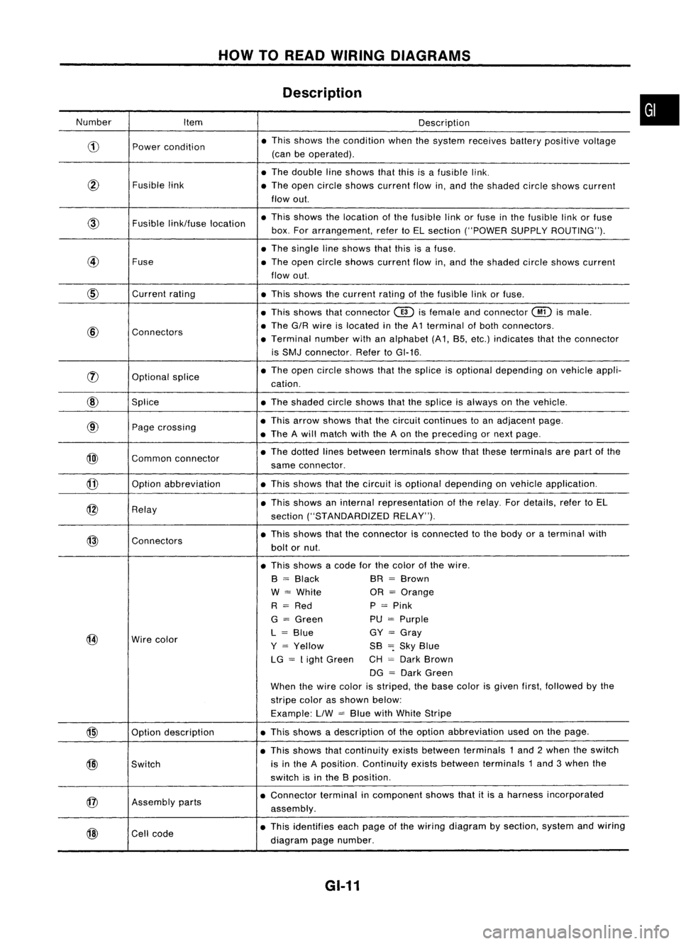
HOWTOREAD WIRING DIAGRAMS
Description
Number Item Description
CD
Power
condition •
This shows thecondition whenthesystem receives batterypositive voltage
(can beoperated) .
• The double lineshows thatthisisafusible link.
@
Fusiblelink
•The open circle shows current flowin,and theshaded circleshows current
flow out.
Fusible
link/fuse location •
This shows thelocation ofthe fusible linkorfuse inthe fusible linkorfuse
box. Forarrangement, refertoEL section ("POWER SUPPLYROUTING") .
• The single lineshows thatthisisafuse.
@
Fuse
•The open circle shows current flowin,and theshaded circleshows current
flow out.
CID
Current
rating
•This shows thecurrent ratingofthe fusible linkorfuse .
• This shows thatconnector
@)
isfemale andconnector
@
ismale .
@
Connectors •
The G/R wire islocated inthe A1 terminal ofboth connectors.
• Terminal numberwithanalphabet (A1, B5, etc.) indicates thattheconnector
is SMJ connector. RefertoGI-16 .
rJ)
Optionalsplice •
The open circle shows thatthesplice isoptional depending onvehicle appli-
cation.
@
Splice •The shaded circleshows thatthesplice isalways onthe vehicle.
@
Page
crossing •
This arrow shows thatthecircuit continues toan adjacent page.
• The Awill match withtheAon the preceding ornext page .
@)
Commonconnector •
The dotted linesbetween terminals showthatthese terminals arepart ofthe
same connector.
@
Option
abbreviation •This shows thatthecircuit isoptional depending onvehicle application.
@
Relay •
This shows aninternal representation ofthe relay. Fordetails, refertoEL
section ("STANDARDIZED RELAY").
@
Connectors •
This shows thattheconnector isconnected tothe body oraterminal with
bolt ornut.
• This shows acode forthe color ofthe wire.
B
=
Black BR
=
Brown
W
=
White OR
=
Orange
R
=
Red P
=
Pink
G
=
Green PU
=
Purple
@
Wire
color L
=
Blue GY
=
Gray
Y
=
Yellow SB
=:
Sky Blue
LG
=
Light Green CH
=
Dark Brown
DG
=
Dark Green
When thewire color isstriped, thebase color isgiven first,followed bythe
stripe colorasshown below:
Example: LlW
=
Blue withWhite Stripe
@
Optiondescription •
This shows adescription ofthe option abbreviation usedonthe page.
• This shows thatcontinuity existsbetween terminals 1and 2when theswitch
@)
Switch is
inthe Aposition. Continuity existsbetween terminals 1and 3when the
switch isinthe Bposition .
@
Assembly
parts •
Connector terminalincomponent showsthatitis aharness incorporated
assembly .
@
Cell
code •
This identifies eachpage ofthe wiring diagram bysection, systemandwiring
diagram pagenumber.
GI-11
•