Page 266 of 1701
DoorMirror
MIRROR
CAUTION:
Be careful nottoscratch doorrearview mirrorbody.
* For Wiring Diagram, referto"POWER DOORMIRROR" inEL section.
REMOVAL -Door mirror
CD
Remove doortrim. Refer to"Door Trim"fordetails, BT-22.
~ Remove innercover fromfront corner ofdoor.
~ Disconnect doormirror harness connector.
@
Remove boltssecuring doormirror, thenremove doormirror assembly.
SEC. 963
Removal:
• Wrap flat-bladed ofscrewdriver withacloth toprevent
scratching rearofdoor mirror. Donot insert screwdriver toofar.
Cloth
Flat-bladed
screwdriver
8T-46 Pawl
58T086
Page 271 of 1701

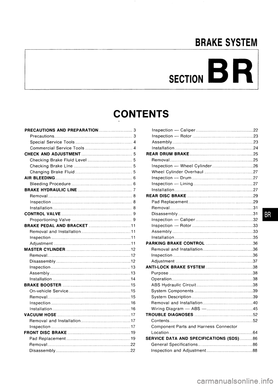
BRAKESYSTEM
SECTION
CONTENTS BR
PRECAUTIONS ANDPREPARATION
3
Precautions 3
Special Service Tools 4
Commercial ServiceTools 4
CHECK ANDADJUSTMENT 5
Checking BrakeFluidLevel 5
Checking BrakeLine 5
Changing BrakeFluid 5
AIR
BLEEDING 6
Bleeding Procedure 6
BRAKE HYDRAULIC LINE 7
Removal 8
Inspection 8
Installation 8
CONTROL VALVE 9
Proportioning Valve 9
BRAKE PEDALANDBRACKET 11
Removal andInstallation 11
Inspection 11
Adjustment 11
MASTER CYLINDER 12
Removal 12
Disassembly 12
Inspection 13
Assembly 13
Installation 14
BRAKE BOOSTER 15
On-vehicle Service 15
Removal 15
Inspection 16
Installation 16
VACUUM HOSE 17
Removal andInstallation 17
Inspection 17
FRONT DISCBRAKE 19
Pad Replacement.. 19
Removal 22
Disassembly 22Inspection
-Caliper 22
Inspection -Rotor 23
Assembly '".23
Installation 24
REAR DRUM BRAKE 25
Removal 25
Inspection -Wheel Cylinder 26
Wheel Cylinder Overhaul 27
Inspection -Drum 27
Inspection -Lining 27
Installation 27
REAR DISCBRAKE 29
Pad Replacement 29
~~s:~::~'~I~':::::::::::'::: ::.::::::::.::::::.::::::::::.::::::.::::::::~~ •••
Inspection -Caliper 32
Inspection -Rotor 33
Assembly 33
Installation 35
PARKING BRAKECONTROL 36
Removal andInstallation 36
Inspection 36
Adjustment ." 37
ANTI-LOCK BRAKESYSTEM 38
Purpose 38
Operation 38
ABS Hydraulic Circuit 38
System Components 39
System Description 39
Removal andInstallation .40
Wiring Diagram -ABS - .45
TROUBLE DIAGNOSES
52
Contents 52
Component PartsandHarness Connector
Location 64
SERVICE DATAANDSPECIFICATIONS (SDS)86
General Specifications 86
Inspection andAdjustment 88
Page 272 of 1701
CONTENTS
(Cont'd.)
When youread wiring diagrams:
• Read GIsection, "HOWTOREAD WIRING DIAGRAMS" .
• See Elsection, "POWER SUPPLYROUTING" forpower distribution circuit.
When youperform troublediagnoses, readGIsection, "HOWTOFOllOW FLOWCHART
IN TROUBLE DIAGNOSES" and"HOW TOPERFORM EFFICIENT DIAGNOSIS FORAN
ELECTRICAL INCIDENT".
Page 315 of 1701
ANTI-LOCKBRAKESYSTEM
Wiring Diagram -ABS -
BR-ABS-01
•
ABS
CONTROL
UNIT
(B111)
LHDmodels
@:
RHOmodels
Refer
to
EL-POWER.
FUSE
BLOCK
(JIB)
~
GY
ffi
IGN
SW
Y
I~I COMBINATION
METER
(ABS WARNING
LAMP)
~@
LIB
@
I
GY
LIB
$-------$
GY (~) LIB
I-
e-
LIB~ ToBR-ABS-O?
I
LIB
13-0
I
FAIL
LAMP
IGNITION
SWITCH
ON orSTART
STOP
DEPRESED LAMP
SWITCH
RELEASED ~
~
P!L
•
~:I
P!L
rn~
I
JUNCTION
BOX
NO.2
(JOINT
CONNECTORS)
1!:i=!J~
PIL
~~
•
PIL
lelIl
9F'~
P!L
14-81
STOP
LAMP
SW
Fa~
l..1..@
B ~~(B115)
5 6
TI1910
1112 W
Refer
tolast page
(Foldout page).
~---------------------------------,
L ~
HBR002
BR-45
Page 316 of 1701
ANTI-LOCKBRAKESYSTEM
Wiring Diagram -ABS -(Coni' d)
BR-ABS-02
ABS
CONTROL
UNIT
(!ID1)
OrAG
L TXD RXD
~ 1~61~
ORIB ~ GY!L GIB
I$~ ~
~ciJ~ ---
~~I
ORIB
GY/L GIB
It It
GY!L
GIB
cr
l I~
i~MO~o~?ic~g~)
~:
JOINT CONNECTOR-5
~ 1*.21~:
GY/L GIB
I I
GY/L
GIB
m
r1l
ORIB
rtl
FUSE
Referto
7 .5A BLOCK EL-POWER.
rn
(JIB)
~
IGNITION
SWITCH
ON orSTART
I
DATALINK
CONNECTOR
FOR CONSULT
(M13)
-----------------------
<0:
LHDmodels
RHOmode Is
@:
GAengine andSRengine
@:
CD20engine
~f1
<0
10
6
*2
<0
9
'
3
,
~~(~)
56j819101112 W
~(~24)
~OR
Refer
tolast page
(Foldout page).
HBR003
BR-46
Page 317 of 1701
ANTI-LOCKBRAKESYSTEM
Wiring Diagram -ABS -(Cont'd)
BR-ABS-03
•
ABS
CONTROL
UNIT
LHO models
RHO models
(jJ:
(8):
GN02
GNO1 GNO
12.81 12.911
3•
9
1
B BB
Ll-l
I
----
)
I
1
I
1
----
']
W@1IDB .
$---$-]1
W
@)
8
-----
(,
-
_.
1 -- I
I I
I I
l.... •
l~t~~8}j~f
-]1
W «(1Q"n B
-----
r-- _
I I
I 1
1 1
l....
'J
R
R
~
..
1
1
I
I
I ....
l
SENSOR
FR-RH
H
~
B
t
I
o
,. 1
1
1
I
I
I
I
1
I
I
1
I
J 1
1
I
1
1
I
I
1
1
1
1
1
I
1
I ....
t
-
rn
JOINT
CONNECTOR
-7
(B109)
1
WB
~ WHEELSPEED
SENSOR
rv
FRONTRH
(1llQj)
W
B
M
WHEELSPEED
SENSOR
rv
FRONTRH
(E 11)
&~(BIT5)
5 6TII9ID 1112W ..In
em),
@ill)
<..!J.g)
GYGY
~(Eli[9)
IIlIITl.IIillJ
GY
Refer
tolast page
(Foldout page).
HBR004
BR-47
Page 318 of 1701
ANTI-LOCKBRAKESYSTEM
Wiring Diagram -ABS -(Cont'd)
BR-ABS-04
ASS
CONTROL
SENSOR UNIT
FR-LH
~
H
~
LHO
models
L
t
•
@:
RHOmodels
0
L
L
-
-
-
--
-ec
,.
)
I
I
I
I
I
I
I
----
1--
']
)
t
----
I
R~ L
I
I
$---$J
I
I
R
L
1
1
-
-
--
I
mJOINT
I
I'-- --
!
I
1
CONNECTOR
I
I
I
-7
I
1
I
(B109)
l--•
1
-----
A@L ]
I$f---J$-J
R
(ffi1)
L
-----
(,
.
I I
-
---
1
I
I
I
--
,I
II
t
)
(
)
-----
-----
R L R
L
M
.>'EELSPEED
M
WHEEL
SPEED
SENSOR SENSOR
-
rvFRONTLH
rvFRONTLH
(eUO)
(8106)
@
~~(@
56 iBl91
...IE.
@,(~)
(tig)
SR SR
BR-48 ~(B109)
illIIIIIIIIIl
GY
Refer
tolast page
(Foldout page).
HBR005
Page 319 of 1701
ANTI-LOCKBRAKESYSTEM
Wiring Diagram -ABS -(Conl'd)
BR-ABS-05
-----
-----
A8S
CONTROL
UNIT
SENSOR
RR-LH
H
~ L
t
"
----
/)
I
I
I
I
I
I
I
I
I
SENSOR
RR-LH
(+)
lY;ll
P
J
r-:l~!
I
JOINT
I .
CONNECTOR-7
I
@QID
r
(8110)
SENSOR
RR-RH
H
1
3•8
1
LG
t
(
....
SENSOR
RR-RH
(+)
~ PU
J
----
'I
/
I
1
1
I
I
I
I
I
I
I
I
I
I
I
I
I
,I
)
•
PU LG
M
WHEELSPEED
SENSOR
rv REARRH
(!W)
P
L
M
WHEELSPEED
SENSOR
rv
REARLH
(ffi?)
15a
([UID ,
@TI)
C!J.g)
GYSR ~(8109)
l:TIIillIIIIIJ
GY
Refer
tolast page
(Foldout page).
HBR006
BR-49