Page 334 of 1701
TROUBLEDIAGNOSES
Component PartsandHarness Connector
Location
RHO models
Dualproportioning
valve
DABS warninglamp
X
1.1
ABS relay box
Brake master cylinder ~
Rear wheel sensors
Ii
Rear rightwheel
sensor connector
[i1
Rear leftwheel
sensor connector
• For LHD models, controlunit
is located onthe opposite side.
SBR047DA
BR-64
Page 352 of 1701

TROUBLEDIAGNOSES
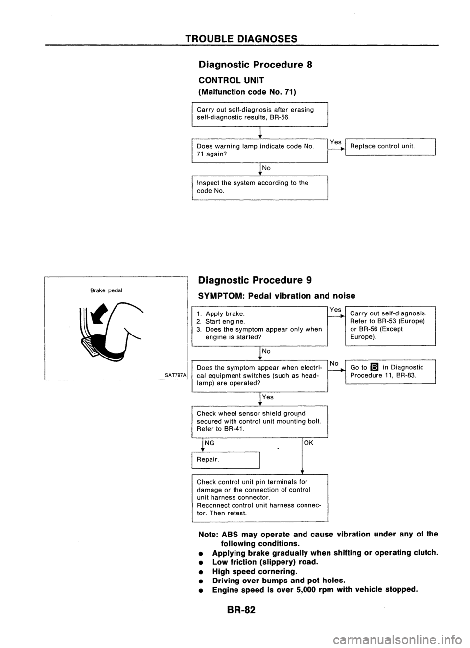
Diagnostic Procedure8
CONTROL UNIT
(Malfunction codeNo.71)
Carry outself-diagnosis aftererasing
self-diagnostic results,BR-56.
Does warning lampindicate codeNo.
71 again?
No
Inspect thesystem according tothe
code No. Yes
Replace controlunit.
Brake pedal Diagnostic
Procedure9
SYMPTOM: Pedalvibration andnoise
No
Does thesymptom appearwhenelectri-
SAT797A
calequipment switches(suchashead-
lamp) areoperated?
1.
Apply brake.
2. Start engine.
3. Does thesymptom appearonlywhen
engine isstarted?
No
Yes
Check wheelsensor shieldgrou.nd
secured withcontrol unitmounting bolt.
Refer toBR-41. Yes
Carryoutself-diagnosis.
Refer toBR-53 (Europe)
or BR-56 (Except
Europe).
Go to
Ii1
inDiagnostic
Procedure 11,BR-83.
OK
Check control unitpinterminals for
damage orthe connection ofcontrol
unit harness connector.
Reconnect controlunitharness connec-
tor. Then retest.
Note: ABSmayoperate andcause vibration underanyofthe
following conditions.
• Applying brakegradually whenshifting oroperating clutch.
• Low friction (slippery) road.
• High speed cornering.
• Driving overbumps andpotholes.
• Engine speedisover 5,000 rpmwith vehicle stopped.
BR-82
Page 353 of 1701

TROUBLEDIAGNOSES
Diagnostic Procedure10
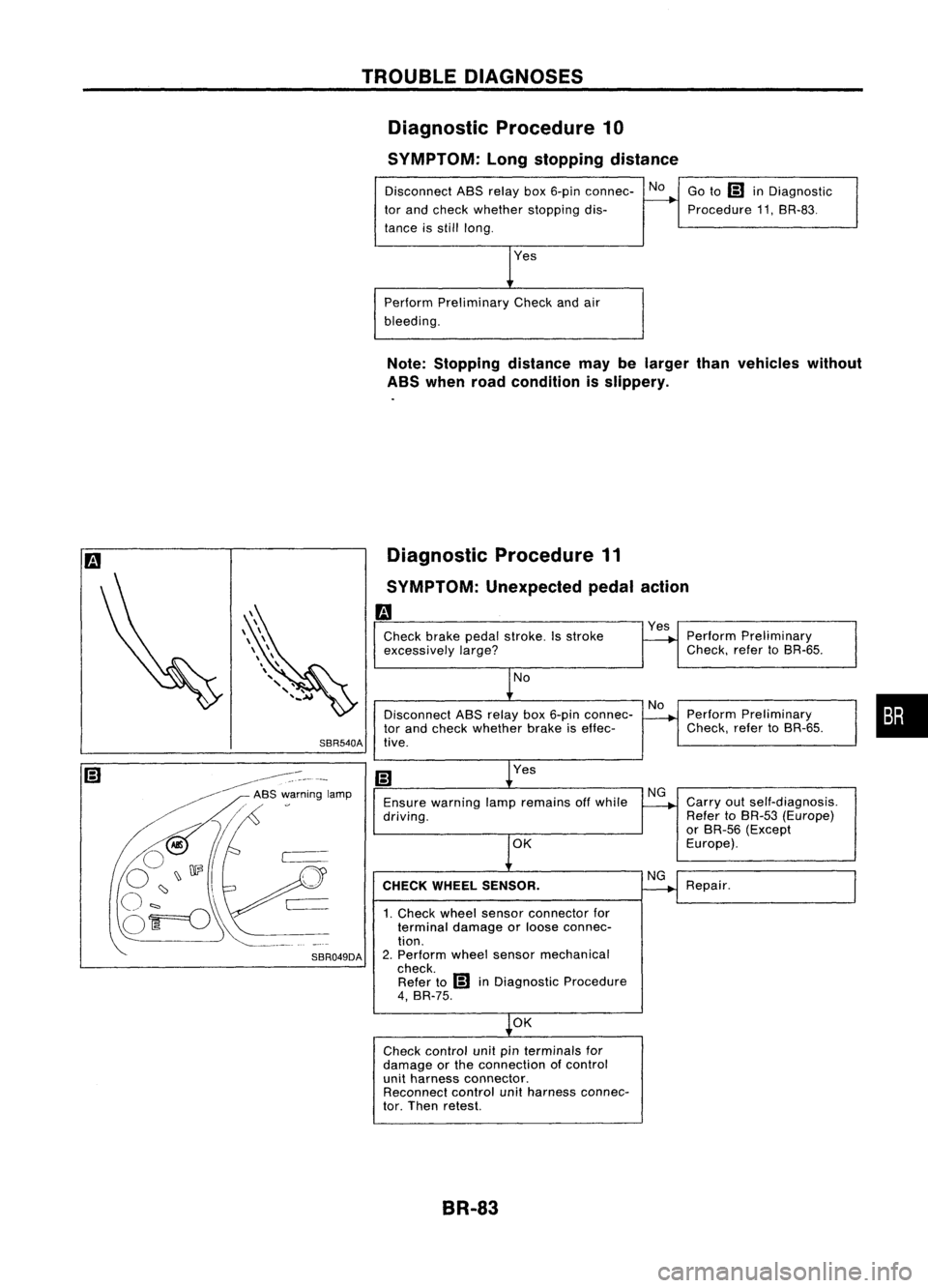
SYMPTOM: Longstopping distance
Disconnect ABSrelay box6-pin connec- No
tor and check whether stopping dis-
tance isstill long.
Perform Preliminary Checkandair
bleeding. Go
to
IiJ
inDiagnostic
Procedure 11.SR-83.
Note: Stopping distancemaybelarger thanvehicles without
ABS when roadcondition isslippery.
Diagnostic Procedure11
SYMPTOM: Unexpected pedalaction
m
Check brakepedalstroke. Isstroke
excessively
large?
No
Disconnect ASSrelay box6-pin connec-
tor and check whether brakeiseffec-
SBR540A tive.
Yes
Ensure warning lampremains offwhile
driving.
OK
CHECK WHEEL SENSOR.
1. Check wheelsensor connector for
terminal damageorloose connec-
tion.
2. Perform wheelsensor mechanical
check. Refer to
IiJ
inDiagnostic Procedure
4, BR-75.
OK
Check control unitpinterminals for
damage orthe connection ofcontrol
unit harness connector.
Reconnect controlunitharness connec-
tor. Then retest.
BR-83
Yes
Perform Preliminary
Check. refertoSR-65.
Perform Preliminary
Check. refertoSR-65.
Carry outself-diagnosis.
Refer toBR-53 (Europe)
or SR-56 (Except
Europe).
Repair.
•
Page 354 of 1701

TROUBLEDIAGNOSES
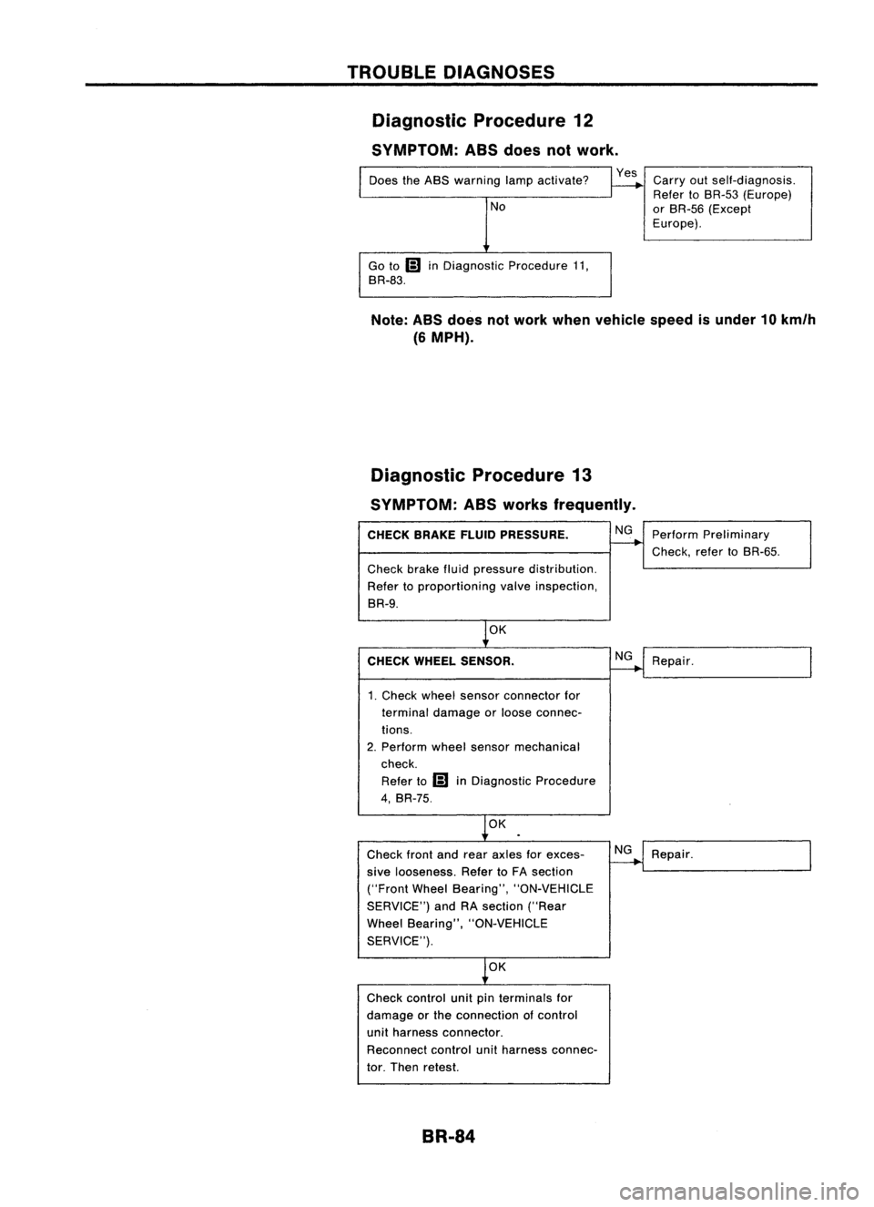
Diagnostic Procedure12
SYMPTOM: ASSdoes notwork.
Does theABS warning lampactivate?
No
Go to
Ii)
inDiagnostic Procedure11,
BR-83.
Yes
Carryoutself-diagnosis.
Refer toBR-53 (Europe)
or BR-55 (Except
Europe).
Note: ABSdoes notwork when vehicle speedisunder 10km/h
(6 MPH).
Diagnostic Procedure13
SYMPTOM: ASSworks frequently.
CHECK BRAKEFLUIDPRESSURE.
Check brakefluidpressure distribution.
Refer toproportioning valveinspection,
BR-9.
OK
CHECK WHEEL SENSOR.
1. Check wheelsensor connector for
terminal damage orloose connec-
tions.
2. Perform wheelsensor mechanical
check.
Refer to
Ii)
inDiagnostic Procedure
4, BR-75.
OK
Check frontandrear axles forexces-
sive looseness. RefertoFA section
("Front WheelBearing", "ON-VEHICLE
SERVICE") andRAsection ("Rear
Wheel Bearing", "ON-VEHICLE
SERVICE").
OK
Check control unitpinterminals for
damage orthe connection ofcontrol
unit harness connector.
Reconnect controlunitharness connec-
tor. Then retest.
BR-84 NG
NG
NG
Perform
Preliminary
Check, refertoBR-55.
Repair.
Repair.
Page 392 of 1701

GROUNDDISTRIBUTION
GROUND CONNECTTO CONN.
NO. CELLCORD
E37/E51 AIRBAG DIAGNOSIS SENSORUNIT(Single
E108 RS-SRS
air bag system)
BRAKE FLUIDLEVEL SWITCH E2EL-WARN
CLEARANCE LAMPLH E50EL-TAILIL
CLEARANCE LAMPRH E33EL-TAILIL
COOLING FANMOTOR-1 (1-modetype) E45 EC-COOLIFHA-A/C
COOLING FANMOTOR-1 (2-modetype-GA
E66 EC-COOLIF
HA-A/C
engine forEurope)
COOLING FANMOTOR-1 (2-modetype-ex-
E46 EC-COOLIF
HA-A/C
eept GAengine forEurope)
COOLING FANMOTOR-2 (1-modetype)
E39 EC-COOLIFHA-A/C
-
COOLING FANMOTOR-2 (2-modetype-GA
E67 EC-COOLiF
HA-A/C
engine forEurope)
COOLING FANMOTOR-2 (2-modetype-ex-
E40 EC-COOLIFHA-A/C
eept GAengine forEurope)
COOLING FANRELAY-1 E12
EC-COOLIFHA-A/C
COOLING FANRELAY-2 E17
EC-COOLIFHA-A/C
COOLING FANRELAY-3 E18EC-COOLIF
HA-A/C
DAYTIME LIGHTUNIT E119EL-DTRL
FRONT FOGLAMP LH E52EL-F/FOG
FRONT FOGLAMP RH
E36EL-F/FOG
FRONT TURNSIGNAL LAMPLH E53EC-TURN
FRONT TURNSIGNAL LAMPRH E32EC-TURN
FRONT WIPERANDWASHER SWITCH E113
EL-WIPER
FUEL FILTER SWITCH
E5EL-WARN
HEADLAMP AIMINGMOTOR UNITLH E48
EL-AIM
HEADLAMP AIMINGMOTOR UNITRH E35 EL-AIM
HEADLAMP LH E49EL-H/LAMP
EL-DTRL
HEADLAMP RH E34EL-H/LAMP
EL-DTRL
HEADLAMP WIPERMOTOR LH E44
EL-HLC
HEADLAMP WIPERMOTOR RH E41EL-HLC
IACV-FICD SOLENOID VALVE(LHDmodels
.
E65 EC-A/CCUTHA-A/C
with CD20 engine)
INHIBITOR SWITCH E222EC-PNP/SWAT-A
IT EL-START
NEUTRAL POSITION SWITCH E220EC-PNP/SW
POWER STEERING OILPRESSURE SWITCH
E3 EC-PST/SW
(RHO models withgasoline engine)
REAR FOGLAMP RELAY E20EL-R/FOG
REAR WIPER ANDWASHER SWITCH E112EL-WIP/R
REAR WIPER RELAY E15EL-WIP/R
SIDE TURN SIGNAL LAMP(Driver side) E1 EL-TURN
WASHER FLUIDLEVEL SWITCH E30EL-WARN
EL-20
Page 510 of 1701
WARNINGLAMPSANDBUZZER
Warning Lamps/Schematic
>-
[[
W
f-
f-
CD
w
(f)
:J
l.L
UG
NATS
SECURITY
INDICATOR
NATSIMMU
ABS ABS
CONTROL
UNIT
OIL OILPRESSURE SWITCH
FUEL
FUELTANKGAUGE UNIT
WASHER
WASHERFLUIDLEVELSWITCH
DOOR
FRONTDOORSWITCH
(Driver's side)
FRONT DOORSWITCH
(Passenger side)
REAR ODOR SWITCH LH
ALTERNATOR PARKING
BRAKESWITCH
FUEL FILTER SWITCH
=
BRAKE
FLUIDLEVEL SWITCH
REAR
ODORSWITCH RH
=
WARNING
BUZZER
UNIT
=
ECM (ECCS
CONTROL
MODULE)
ECM
(ENGINE
CONTROL
MODULE)
I
U
f- W
H (f)
3:f-
:J
(f)[[
l.L
Zf-
O(f)
H
f-L
HO
Z
BELT
C!JZ
HO
BRAKE
Q)
(I)
D.
rl
0
Q)
L
D
::J
0
W
E
L
C
0
ro
""-
D
Q)
(I)
(f)
rl
Q)
ro
D
D
'M
C
0
rl
ro
E
ro
L
~
Q) Q)
.....
u
C C
(I)
ro
.M
Q)
.M
ro
::J
.0
OJ
C
OJ
.M
.c
c
.M
C
rl
U
Q)
OJ
Q)
ro
L
+'
C
L
0
ro
Q) Q) Q)
.....
""-
I
C C
(I)
GLOW
.M
rl
.
M
::J
.....
L
rl
Q)
rl
D.
0
0
(I)
0
Q)
0
(I)
Q)
(I)
L
u
D
ro
.M
ro
0
x
I
C!J
0
C!J
l.L
W
lD
MALFUNCTION
@@~@@@
INDICATOR
AIRBAG
AIRBAG
DIAGNOSIS
SENSOR
UNIT
HEL082
EL-138
Page 690 of 1701
FRONTAXLE
Front
~ :N.m (kg-m, ft-Ib)
10
@~
98•118 (10•12, 72-87)
SFA619B
CD
Drive shaft
@
Inner grease seal
@
Knuckle
@
Baffle plate
@
ABS sensor
@
Wheel bearing assembly
(J)
Snap ring
@
Outer grease seal
@
Hubbolt
@)
Wheel hub
@
Plain washer
@
Wheel bearing locknut
@
Insulator
@
Adjusting cap
@
Cotter pin
@
Discrotor
@
Wheel nut
Wheel HubandKnuckle
REMOVAL
CAUTION: Before removing thefront axleassembly, disconnect theABS
wheel sensor fromtl1eassembly. Thenmove itaway fromthe
front axleassembly area.Failure todo somay result indam-
age tothe sensor wiresandthesensor becoming inoperative.
1. Remove wheelbearing locknut.
2. Remove brakecaliper assembly androtor.
SFA110A Brakehoseneed notbedisconnected frombrake caliper.
In this case, suspend caliperassembly withwire soasnot to
stretch brakehose.
Be careful nottodepress brakepedal, orpiston willpop out.
Make surebrake hoseisnot twisted.
FA-8
Page 1368 of 1701

Normallyopen
HOW
TOREAD WIRING DIAGRAMS
Description (Cont'd)
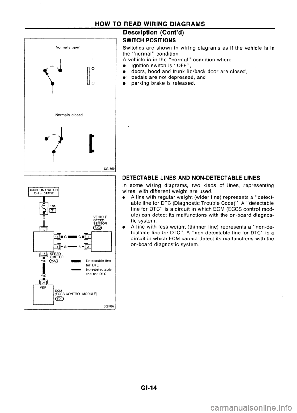
SWITCH POSITIONS
Switches areshown inwiring diagrams asifthe vehicle isin
the "normal" condition.
A vehicle isin the "normal" conditionwhen:
• ignition switchis"OFF",
• doors, hoodandtrunk lid/back doorareclosed,
• pedals arenotdepressed, and
• parking brakeisreleased.
Normally closed
5GI860DETECTABLE LINESANDNON-DETECTABLE LINES
In some wiring diagrams, twokinds oflines, representing
wires, withdifferent weightareused.
• Aline with regular weight(widerline)represents a"detect-
able lineforDTC (Diagnostic TroubleCode)".A"detectable
line forDTC" isacircuit inwhich ECM(ECCS control mod-
ule) candetect itsmalfunctions withtheon-board diagnos-
tic system.
• Aline with lessweight (thinner line)represents a"non-de-
tectable lineforDTC", A"non-detectable lineforDTC" isa
circuit inwhich ECMcannot detectitsmalfunctions withthe
on-board diagnostic system.
SGI862
_
:Detectable line
for DTC
- :Non-detectable
line forDTC
Y
~ VEHICLE
SPEED SENSOR
@
lill-G_G~
llli-G-R~
I~I
SPEED
.,=
OMETER
Y/G
@Z)
I
Y/G
[]26
VSP ECM
(ECCS CONTROL MODULE)
@)
GI-14