Page 451 of 1701
HEADLAMP-Headlamp AimingControl -
Wiring Diagram -AIM -(Cont'd)
RHD MODELS
EL-AIM-03
HEADLAMPAIMING
MOTOR RH
@
-
WIG~
-
BIR~
Nextpage
-
BIL~
-
RIW~
HEADLAMP AIMING
MOTOR LH
rn
Refer
toEL-POWER.
FUSE
BLOCK
(JIB)
(E106)
(E10!)
CHID
.. ------- WIG~~ WIG--- __
.. ----- BIR~~ BIR-----
r=B/L~~B/L
I
I=.R/W ~~RIW-----
T-i=i=r~
P
WIG
BIR B/LRIW
~mmmlFh
rITfu\ ~~
~ GY,GY
Refer
tolast page
(Foldout page).
•
HEL021
EL-79
Page 452 of 1701
HEADLAMP-Headlamp AimingControl -
Wiring Diagram -AIM -(Cont'd)
EL-AIM-04
G
J
FUSE]
BLOCK
(JIB)
Referto
----- ~EL-POWER.
I
a.
3 -,
----I
N.B
I
(Et06)
R/L
RIG
I
Refer
to
EL-POWER.
LIGHTING SWITCH
.....
<€l-
WIG
.....
Preceding
<&
B/R
.....
page
<@-
B/L
.....
<@-
RIW
U:i=U
ll:iJl ~
IbjJJ
WIG
B/R B/LRIW HEADLAMP
AIMING
SWITCH
(8TI)
~ B
I
B
rn~
IJOINT
CONNECTOR-4
~
L4=JJ
B
I
T-,
n
B BBB
1
!..1
1
(M2B)
m:m:I:illIillTI ~
~P
EL-80
Refer
tolast page
(Foldout page).
HEL022
Page 453 of 1701

HEADLAMP-Headlamp AimingControl -
Reversing
relay
Thermistor
Reversing
relay
Thermistor
Reversing
relay
::- Thermistor
+
BATIERY
A o
1
2
3
SEL465M
+
BATIERY
o
1
2
3
SEL364P
+
BATIERY
o
1
2
3
SEL365P Description
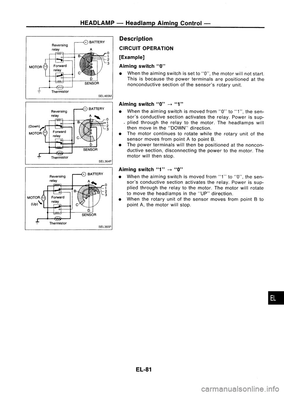
CIRCUIT OPERATION
[Example]
Aiming switch
"0"
• When theaiming switchisset to"0", themotor willnotstart.
This isbecause thepower terminals arepositioned atthe
nonconductive sectionofthe sensor's rotaryunit.
Aiming switch
"0"
-t
"1"
• When theaiming switchismoved from"0"to"1", thesen-
sor's conductive sectionactivates therelay. Power issup-
. plied through therelay tothe motor. Theheadlamps will
then move inthe "DOWN" direction.
• The motor continues torotate whiletherotary unitofthe
sensor movesfrompoint Ato point B.
• The power terminals willthen bepositioned atthe noncon-
ductive section, disconnecting thepower tothe motor. The
motor willthen stop.
Aiming switch"1"
-t
"0"
• When theaiming switchismoved from"1"to"0", thesen-
sor's conductive sectionactivates therelay. Power issup-
plied through therelay tothe motor. Themotor willrotate
to move theheadlamps inthe "UP" direction.
• When therotary unitofthe sensor movesfrompoint Bto
point A,the motor willstop.
EL-81
•
Page 473 of 1701

GEL001EXTERIOR
LAMP
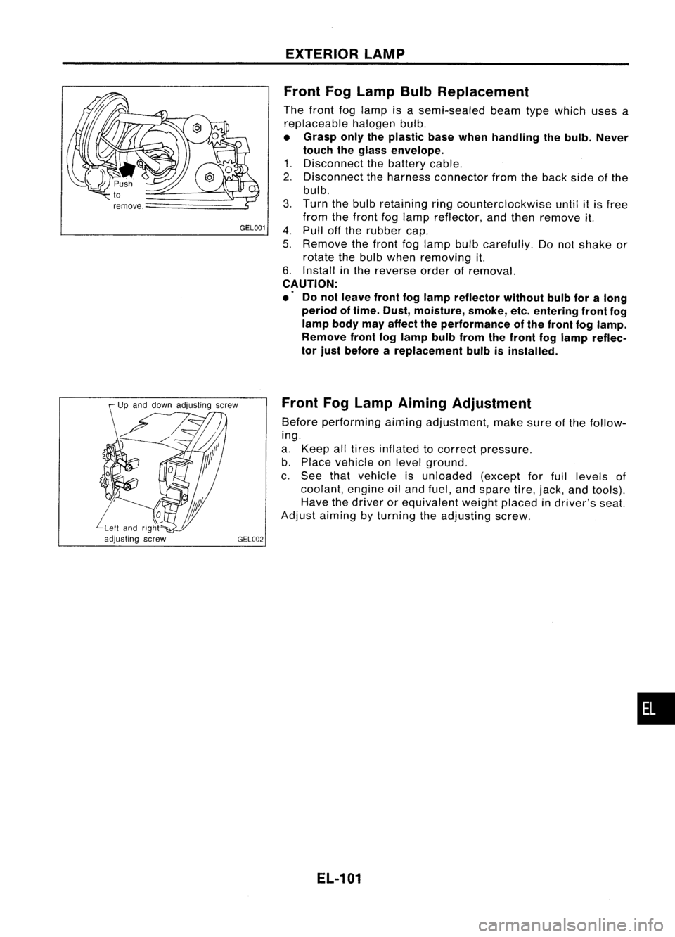
Front FogLamp BulbReplacement
The front foglamp isasemi-sealed beamtypewhich usesa
replaceable halogenbulb.
• Grasp onlytheplastic basewhen handling thebulb. Never
touch theglass envelope.
1. Disconnect thebattery cable.
2. Disconnect theharness connector fromtheback sideofthe
bulb.
3. Turn thebulb retaining ringcounterclockwise untilitis free
from thefront foglamp reflector, andthen remove it.
4. Pull offthe rubber cap.
5. Remove thefront foglamp bulbcarefully. Donot shake or
rotate thebulb when removing it.
6. Install inthe reverse orderofremoval.
CAUTION:
.' Donot leave frontfoglamp reflector withoutbulbforalong
period oftime. Dust, moisture, smoke,etc.entering frontfog
lamp bodymayaffect theperformance ofthe front foglamp.
Remove frontfoglamp bulbfrom thefront foglamp reflec-
tor just before areplacement bulbisinstalled.
Front FogLamp Aiming Adjustment
Before performing aimingadjustment, makesureofthe follow-
ing.
a. Keep alltires inflated tocorrect pressure.
b. Place vehicle onlevel ground.
c. See thatvehicle isunloaded (exceptforfull levels of
coolant, engineoiland fuel, andspare tire,jack, andtools).
Have thedriver orequivalent weightplaced indriver's seat.
Adjust aiming byturning theadjusting screw.
EL-101
•
Page 1491 of 1701

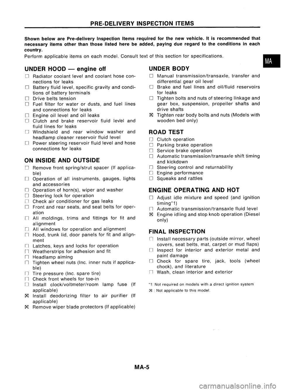
PRE-DELIVERYINSPECTIONITEMS
Shown belowarePre-delivery InspectionItemsrequired forthe new vehicle. Itis recommended that
necessary itemsotherthanthose listedherebeadded, payingdueregard tothe conditions ineach
country.
Perform applicable itemsoneach model. Consult textofthis section forspecifications .
UNDER HOOD-engine off
o
Radiator coolantlevelandcoolant hosecon-
nections forleaks
o
Battery fluidlevel, specific gravityandcondi-
tions ofbattery terminals
o
Drive beltstension
D
Fuel filter forwater ordusts, andfuel lines
and connections forleaks
[] Engine oillevel andoilleaks
D
Clutch andbrake reservoir fluidlevel and
fluid lines forleaks
o
Windshield andrear window washerand
headlamp cleanerreservoir fluidlevel
D
Power steering reservoir fluidlevel andhose
connections forleaks
ON INSIDE ANDOUTSIDE
D
Remove frontspring/strut spacer(Ifapplica-
ble)
D
Operation ofall instruments, gauges,lights
and accessories
o
Operation ofhorn(s), wiperandwasher
[] Steering lockforoperation
[] Check airconditioner forgas leaks
o
Front andrear seats, andseat belts foroper-
ation
n
All moldings, trimsandfittings forfitand
alignment
[J
Allwindows foroperation andalignment
n
Hood, trunklid,door panels forfitand align-
ment
[1
Latches, keysandlocks foroperation
rl
Weatherstrips foradhesion andfit
[l
Headlamp aiming
I~ Tighten wheelnuts(Inc. inner nutsifapplica-
ble)
IJ Tire pressure (Inc.spare tire)
Il
Check frontwheels fortoe-in
IJ Install clock/voltmeter/room lampfuse(If
applicable)
~ Install deodorizing filtertoair purifier (If
applicable)
~ Remove wiperbladeprotectors (Ifapplicable)
UNDER
BODY
o
Manual transmission/transaxle, transferand
differential gearoillevel
D
Brake andfuel lines andoil/fluid reservoirs
for leaks
D
Tighten boltsandnuts ofsteering linkageand
gear box,suspension, propellershaftsand
drive shafts
~ Tighten rearbody boltsandnuts (Models with
wooden bedonly)
ROAD TEST
D
Clutch operation
D
Parking brakeoperation
[J
Service brakeoperation
D
Automatic transmission/transaxle shifttiming
and kickdown
[] Steering controlandreturnability
o
Engine performance
D
Squeaks andrattles
ENGINE OPERATING ANDHOT
D
Adjust idlemixture andspeed (andignition
timing*1)
n
Automatic transmission/transaxle fluidlevel
~ Engine idlingandstop knob operation (Diesel
only)
FINAL INSPECTION
n
Install necessary parts(outside mirror,wheel
covers, seatbelts, mat,carpet ormud flaps)
[1
Inspect forinterior andexterior metaland
paint damage
[] Check forspare tire,jack, tools (wheel
chock), andliterature
n
Wash, cleaninterior andexterior
"1: Not required onmodels withadirect ignition system
~ :Not appiicable tothis model.
•
MA-5
Page 1498 of 1701

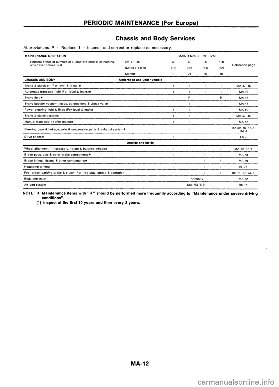
PERIODICMAINTENANCE (ForEurope)
Chassis andBody Services
Abbreviations: R
=
Replace. Inspect,andcorrect orreplace asnecessary.
MAINTENANCE OPERATION
MAINTENANCEINTERVAL
Steering gear
&
linkage, axle
&
suspension parts
&
exhaust system*
OutsideandInside
Wheel alignment (Ifnecessary, rotate
&
balance wheels)
Brake pads,disc
&
other brake components*
Brake linings, drums
&
other components*
Headlamp aiming
Foot brake, parking brake
&
clutch (Forfreeplay, stroke
&
operation)
Annually120
Reference page
(72)
48
MA-47,45MA-46
R MA-47
MA-48
MA-50
MA-47,45 MA-45
MA-50, 45,FA-5,
RA-4
FA-7
MA-49, FA-6
MA-48
MA-49 EL-75
BR-11, 37,CL-5
MA-52 RS-11
90
(54)
36
R
60
See NOTE (1)
(36)
24
30
(18)
12
km
x1,000
(Miles x1,000)
Months
Underhood andunder vehicle
Perform
eitheratnumber ofkilometers (miles)ormonths,
whichever comesfirst.
Brake booster vacuum hoses,connections
&
check valve
Brake
&
clutch oil(For level
&
leaks)*
Automatic transaxlefluid(Forlevel
&
leaks)*
Brake f1uid*
CHASSIS
ANDBODY
Power steering fluid
&
lines (Forlevel
&
leaks)
Brake
&
clutch systems
Manual transaxle oil(For leaks)*
Drive shafts*
Air bag system
Body
corrosion
NOTE:
*
Maintenance itemswith
"*"
should beperformed morefrequently accordingto"Maintenance undersevere driving
conditions" .
(1) Inspect atthe first 10years andthen every 2years.
MA-12