Page 1054 of 1701

TROUBLEDIAGNOSIS FORNON-DETECTABLE ITEMS
SYSTEM DESCRIPTION Idle
AirControl Valve(IACV) -Auxiliary Air
Control (AAC)Valve
Camshaft positionsensor Engine
speed
~
I
Amount ofintake air
Mass airflow sensor
I
Engine coolant temperature sensor Engine
coolant temperature
I
Ignition switch Start
signal
I
Throttle position sensor Throttle
"position
I
ECM
Inhibitor switch(A/Tmodels)/ Park/Neutral
position (ECCS
control
!
IACV-AAC valve
I
Neutral position switch(M/Tmodels)
module)
Air conditioner switch Air
conditioner operation
Power steering oilpressure switch Power
steering loadsignal
I
Battery Battery
voltage
Vehicle speedsensor Vehicle
speed
I
l
Cooling fan Cooling
fanoperation
I
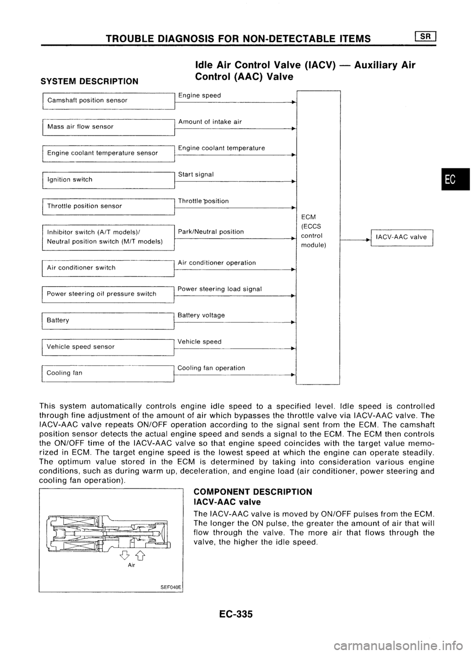
This system automatically controlsengineidlespeed toaspecified level.Idlespeed iscontrolled
through fineadjustment ofthe amount ofair which bypasses thethrottle valveviaIACV-AAC valve.The
IACV-AAC valverepeats ON/OFF operation according tothe signal sentfrom theECM. Thecamshaft
position sensordetects theactual engine speedandsends asignal tothe ECM. TheECM thencontrols
the ON/OFF timeofthe IACV-AAC valvesothat engine speedcoincides withthetarget valuememo-
rized inECM. Thetarget engine speedisthe lowest speedatwhich theengine canoperate steadily.
The optimum valuestored inthe ECM isdetermined bytaking intoconsideration variousengine
conditions, suchasduring warmup,deceleration, andengine load(airconditioner, powersteering and
cooling fanoperation).
COMPONENTDESCRIPTION
IACV-AAC valve
The IACV-AAC valveismoved byON/OFF pulsesfromtheECM.
The longer theONpulse, thegreater theamount ofair that will
flow through thevalve. Themore airthat flows through the
valve, thehigher theidle speed.
Air SEF040E
EC-335
•
Page 1055 of 1701
TROUBLEDIAGNOSIS FORNON-DETECTABLE ITEMS~
Idle AirControl Valve(IACV) -Auxiliary Air
Control (AAC)Valve(Cont'd)
EC-AAC/V-01
Refer toEL-POWER.
ECM (ECCS
CONTROL
MODULE)
C£I)
~
~GY ~~
GIIDID
S
BR
I
$-~
BR BR
1r.fJ1
@)
1$1
rn>
(E203) (E201)
BR SR
*_1
I
BR
~I
IACV-AAC
VALVE
(E213)
~ SB
I
SB
14J1
(E227)
(F12)
SB
I
SB
~
ISC
~ (E213)
~@
@
SR~GY
@:
AlTmodels
:
MITmodels
... :Detectable line
for DTC
---: Non-detectable
line forDTC
C£I)
L
EC-336 HEC015
Page 1056 of 1701

•IGN TIMING ADJ.
0
TROUBLE
DIAGNOSIS FORNON-DETECTABLE ITEMS
[ill
Idle AirControl Valve(IACV) -Auxiliary Air
Control (AAC)Valve(Cont'd)
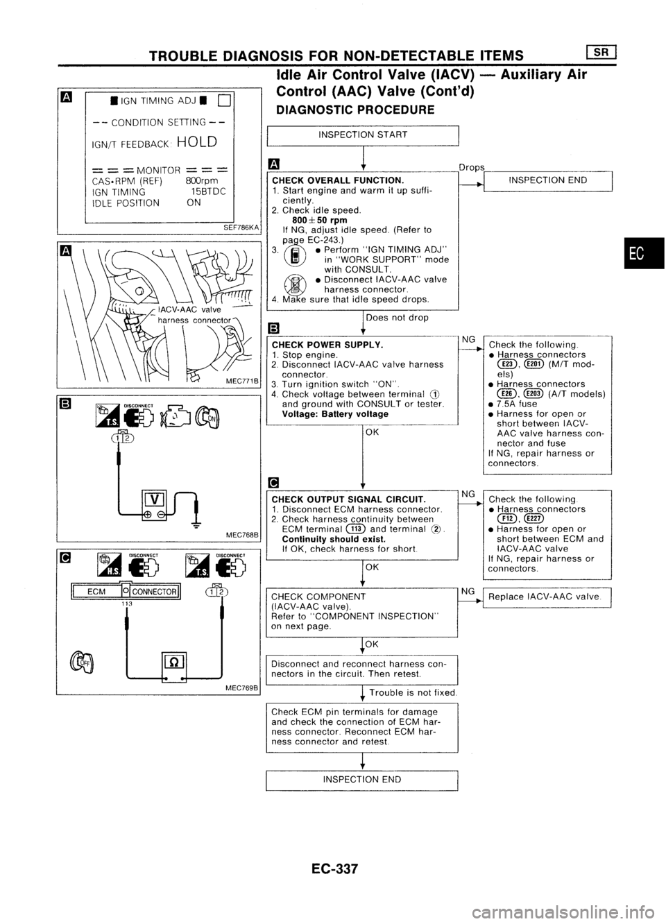
DIAGNOSTIC PROCEDURE
-- CONDITION SETIING--
IGN/T FEEDBACK HOLD INSPECTION
START
~i5 ~i5
ECM
E[CONNECTORII
cffb
113
=
= =
MONITOR
CAS. RPM (REF)
IGN TIMING
IDLE POSITION
---
---
800rpm
15BTDC
ON
SEF786KA
MEC768B CHECK
OVERALL FUNCTION.
1. Start engine andwarm itup suffi-
ciently.
2. Check idlespeed.
800::1:50
rpm
If NG, adjust idlespeed. (Referto
(l)
e
EC-243.)
3. .. •Perform "IGNTIMING ADJ"
I!I
in"WORK SUPPORT" mode
with CONSULT.
~ •Disconnect IACV-AACvalve
5
harness connector.
4. Ma esure thatidlespeed drops.
Does notdrop
CHECK POWER SUPPLY.
1. Stop engine.
2. Disconnect IACV-AACvalveharness
connector.
3. Turn ignition switch"ON".
4. Check voltage between terminal
G)
and ground withCONSULT ortester.
Voltage: Batteryvoltage
OK
[!1
CHECK OUTPUT SIGNALCIRCUIT.
1. Disconnect ECMharness connector.
2. Check harness continuity between
ECM terminal
CTID
andterminal
(2).
Continuity shouldexist.
If OK, check harness forshort
OK
CHECK COMPONENT
(IACV-AAC valve).
Refer to"COMPONENT INSPECTION"
on next page.
OK Drops
NG
NG
NG INSPECTION
END
Check thefollowing .
• Harness connectors
@D,
([ill)(M/Tmod-
els)
• Harness connectors
@,
@
(A/T
models)
• 7.5A fuse
• Harness foropen or
short between IACV-
AAC valve harness con-
nector andfuse
If NG, repair harness or
con nectors.
Check thefollowing.
• Harness connectors
@,@D
• Harness foropen or
short between ECMand
IACV-AAC valve
If
NG, repair harness or
connectors.
Replace IACV-AAC valve.
•
Disconnect andreconnect harnesscon-
nectors inthe circuit Thenretest
Trouble isnot fixed.
Check ECMpinterminals fordamage
and check theconnection ofECM har-
ness connector. ReconnectECMhar-
ness connector andretest
INSPECTION END
EC-337
Page 1057 of 1701
IACV-AACvalve
Disconnect IACV-AACvalveharness connector.
• Check IACV-AAC valveresistance.
Resistance: Approximately 100[at25°C (77°F)]
• Check plunger forseizing orsticking.
• Check forbroken spring.
MEC770B
TROUBLE
DIAGNOSIS FORNON-DETECTABLE ITEMS
[ill
Idle AirControl Valve(IACV) -Auxiliary Air
Control (AAC)Valve(Cont'd)
COMPONENT INSPECTION
EC-338
Page 1400 of 1701

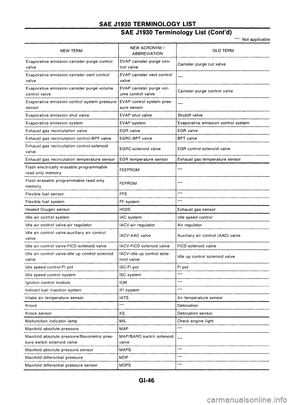
SAEJ1930 TERMINOLOGY LIST
SAE J1930 Terminology List(Cont'd)
***:
Not applicable
NEW TERM NEW
ACRONYM /
OLDTERM
ABBREVIATION
Evaporative emissioncanisterpurgecontrol EVAPcanister purgecon-
Canister purgecutvalve
valve trol
valve
Evaporative emissioncanisterventcontrol EVAPcanister ventcontrol
***
valve valve
Evaporative emissioncanisterpurgevolume EVAPcanister purgevol-
Canister purgecontrol valve
control valve ume
control valve
Evaporative emissioncontrolsystem pressure EVAP
control system pres-
***
sensor suresensor
Evaporative emissionshutvalve EVAP
shutvalve Shutoffvalve
Evaporative emissionsystem EVAPsystem Evaporative
emissioncontrolsystem
Exhaust gasrecirculation valve EGR
valve EGRvalve
Exhaust gasrecirculation control-BPTvalveEGRC-BPT valve BPT
valve
Exhaust gasrecirculation control-solenoid
EGRC-solenoidvalveEGR
control solenoid valve
valve
Exhaust gasrecirculation temperaturesensorEGRtemperature sensorExhaustgastemperature sensor
Flash electrically erasableprogrammable
FEEPROM
***
read onlymemory
Flash erasable programmable readonly
FEPROM
**.
memory
Flexible fuelsensor FFS
***
Flexible fuelsystem
FFsystem
***
Heated Oxygen sensor H02SExhaustgassensor
Idle aircontrol system lACsystem Idlespeed control
Idle aircontrol valve-air regulator IACV-airregulator Airregulator
Idle aircontrol valve-auxiliary aircontrol
IACV-AACvalve Auxiliaryaircontrol (AAC)valve
valve
Idle aircontrol valve-FICO solenoidvalve
IACV-FICDsolenoidvalve FICOsolenoid valve
Idle aircontrol valve-idle upcontrol solenoid IACV-idleupcontrol sole-
Idleupcontrol solenoid valve
valve noidvalve
Idle speed control-FI pot ISC-FIpot FIpot
Idle speed control system ISCsystem
***
Ignition controlmodule ICM
***
Indirect fuelinjection system IFIsystem
***
Intake airtemperature sensor IATS Airtemperature sensor
Knock
***
Detonation
Knock sensor
KSDetonation
sensor
Malfunction indicatorlamp MIL
Checkengine light
Manifold absolutepressure MAP
***
Manifold absolutepressure/Barometric pres-MAP/BARO switchsolenoid
***
sure switch solenoid valve valve
Manifold absolutepressure sensor MAPS
**.
Manifold differential pressure MOP
***
Manifold differential pressuresensor MOPS
***
GI-46
Page 1629 of 1701
SUPPLEMENTALRESTRAINTSYSTEM(SRS)
Description
The airbag deploys ifthe diagnosis sensorunitactivates whiletheignition switchisinthe "ON" or
"START" position.
Single anddual airbag systems
Ignition
switch
(ON orSTART)
Driver
air
bag module
Diagnosis sensorunit
• Auxiliary powersource (condenser)
• CPU
Battery
Seat beltpre-tensioner
G-Iorce whendecelerating
(greater thanthepredetermined setting)
o
Drive circuit
• G sensor
• Saling sensor Passenger
airbag module
(For dual airbag system)
MRS069AB
Mechanical sensor
Seat belt Mechanical
trigger
Retractor shaft Piston
andwire rope
•
Combined intoseat beltretractor
SRS126
RS-9