Page 1365 of 1701

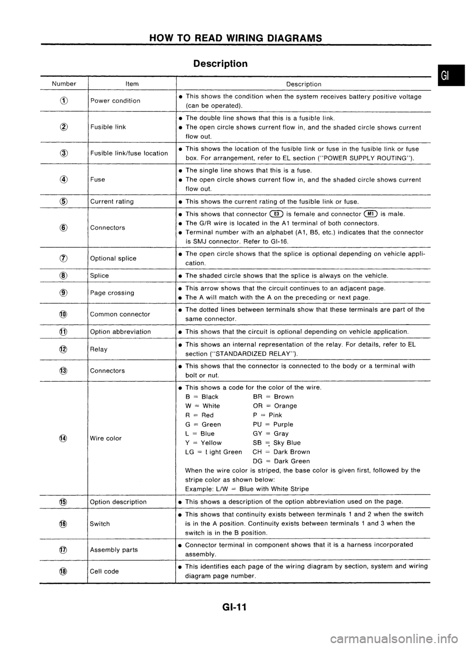
HOWTOREAD WIRING DIAGRAMS
Description
Number Item Description
CD
Power
condition •
This shows thecondition whenthesystem receives batterypositive voltage
(can beoperated) .
• The double lineshows thatthisisafusible link.
@
Fusiblelink
•The open circle shows current flowin,and theshaded circleshows current
flow out.
Fusible
link/fuse location •
This shows thelocation ofthe fusible linkorfuse inthe fusible linkorfuse
box. Forarrangement, refertoEL section ("POWER SUPPLYROUTING") .
• The single lineshows thatthisisafuse.
@
Fuse
•The open circle shows current flowin,and theshaded circleshows current
flow out.
CID
Current
rating
•This shows thecurrent ratingofthe fusible linkorfuse .
• This shows thatconnector
@)
isfemale andconnector
@
ismale .
@
Connectors •
The G/R wire islocated inthe A1 terminal ofboth connectors.
• Terminal numberwithanalphabet (A1, B5, etc.) indicates thattheconnector
is SMJ connector. RefertoGI-16 .
rJ)
Optionalsplice •
The open circle shows thatthesplice isoptional depending onvehicle appli-
cation.
@
Splice •The shaded circleshows thatthesplice isalways onthe vehicle.
@
Page
crossing •
This arrow shows thatthecircuit continues toan adjacent page.
• The Awill match withtheAon the preceding ornext page .
@)
Commonconnector •
The dotted linesbetween terminals showthatthese terminals arepart ofthe
same connector.
@
Option
abbreviation •This shows thatthecircuit isoptional depending onvehicle application.
@
Relay •
This shows aninternal representation ofthe relay. Fordetails, refertoEL
section ("STANDARDIZED RELAY").
@
Connectors •
This shows thattheconnector isconnected tothe body oraterminal with
bolt ornut.
• This shows acode forthe color ofthe wire.
B
=
Black BR
=
Brown
W
=
White OR
=
Orange
R
=
Red P
=
Pink
G
=
Green PU
=
Purple
@
Wire
color L
=
Blue GY
=
Gray
Y
=
Yellow SB
=:
Sky Blue
LG
=
Light Green CH
=
Dark Brown
DG
=
Dark Green
When thewire color isstriped, thebase color isgiven first,followed bythe
stripe colorasshown below:
Example: LlW
=
Blue withWhite Stripe
@
Optiondescription •
This shows adescription ofthe option abbreviation usedonthe page.
• This shows thatcontinuity existsbetween terminals 1and 2when theswitch
@)
Switch is
inthe Aposition. Continuity existsbetween terminals 1and 3when the
switch isinthe Bposition .
@
Assembly
parts •
Connector terminalincomponent showsthatitis aharness incorporated
assembly .
@
Cell
code •
This identifies eachpage ofthe wiring diagram bysection, systemandwiring
diagram pagenumber.
GI-11
•
Page 1366 of 1701

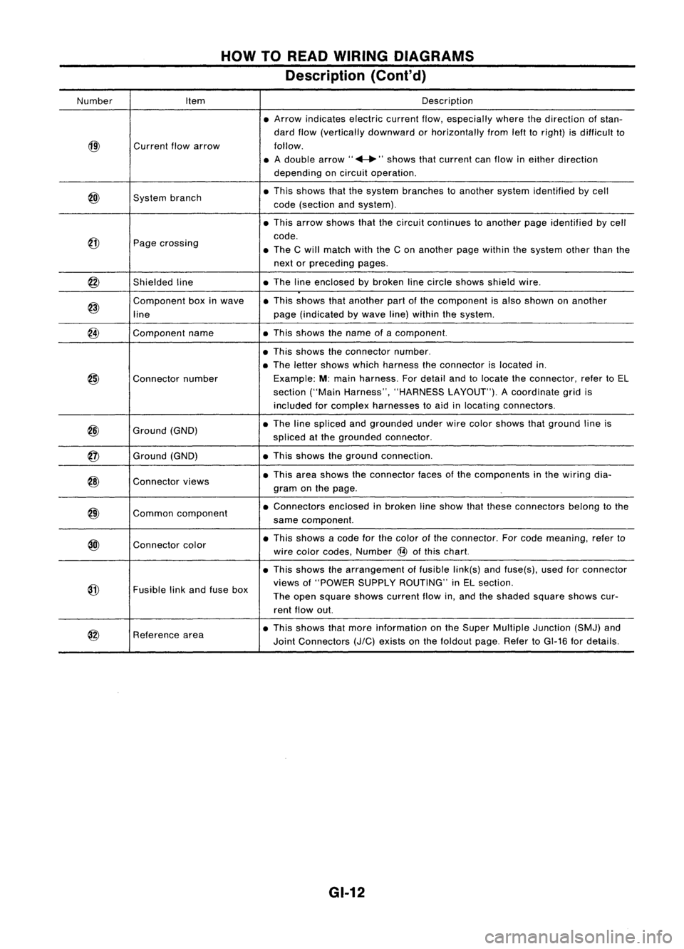
HOWTOREAD WIRING DIAGRAMS
Description (Cont'd)
Number Item Description
• Arrow indicates electriccurrentflow,especially wherethedirection ofstan-
dard flow(vertically downward orhorizontally fromlefttoright) isdifficult to
@)
Current
flowarrow follow.
• Adouble arrow" ...."shows thatcurrent canflow ineither direction
depending oncircuit operation .
@)
System
branch •
This shows thatthesystem branches toanother systemidentified bycell
code (section andsystem) .
• This arrow shows thatthecircuit continues toanother pageidentified bycell
@
code.
Page crossing
•The Cwill match withtheCon another pagewithin thesystem otherthanthe
next orpreceding pages.
@
Shieldedline •
The lineenclosed bybroken linecircle shows shieldwire.
@)
Component
boxinwave •
This shows thatanother partofthe component isalso shown onanother
line page
(indicated bywave line)within thesystem.
@
Component
name •This shows thename ofacomponent.
• This shows theconnector number.
• The letter shows whichharness theconnector islocated in.
@)
Connector
number Example:
M:main harness. Fordetail andtolocate theconnector, refertoEL
section ("MainHarness", "HARNESS LAYOUT").Acoordinate gridis
included forcomplex harnesses toaid inlocating connectors .
@
Ground
(GND) •
The linespliced andgrounded underwirecolor shows thatground lineis
spliced atthe grounded connector.
@
Ground
(GND) •
This shows theground connection.
@)
Connector
views •
This area shows theconnector facesofthe components inthe wiring dia-
gram onthe page .
@)
Common
component •
Connectors enclosedinbroken lineshow thatthese connectors belongtothe
same component.
@l
Connector
color •
This shows acode forthe color ofthe connector. Forcode meaning, referto
wire color codes, Number
@
ofthis chart.
• This shows thearrangement offusible link(s)andfuse(s), usedforconnector
@
views
of"POWER SUPPLYROUTING" inEL section.
Fusible linkand fuse box
Theopen square showscurrent flowin,and theshaded squareshowscur-
rent flow out.
@
Reference
area •
This shows thatmore information onthe Super Multiple Junction (SMJ)and
Joint Connectors
(J/C)
exists onthe foldout page.RefertoGI-16 fordetails.
GI-12
Page 1438 of 1701
TROUBLEDIAGNOSES
Wiring Diagram -HEATER -
HA-HEATER-01
<0:
LHOmodels
Refer toEL-POWER.
(8):
RHOmodels
@:
ForEurope andIsrael
@:
Except@
t
LIB
~
~~~~ST""
L/W L/YL/R
.,--I-~r=t
r
RIG.
To
EL-m
t
L/WL/YL!R LIBRIG
I
:4
II
:31 12~1
Ii2'nJ n1=iI
FAN
SWITCH
@
ILL. ~
~ ~
B B
~ol __
1
I
I I
<
------.~o--l
JOINT
B CONNECTOR-4
1
Li t
J
Lt
1
B
{J
gj.
B~Next page
\~
~/
\~
~
~/
<0
FUSE
15A BLOCK
T
(JIB)
L..:..J ~
IN31
•
L!W L/W
L.l
I
L/W
~1
M
BLOWER
MOTOR
~
I!.j.JJ
LIB
~--------------------,
i~@~~:
I~W 2Wi
I I
I I
L
~
l1IillIITillIil
~
~P
Refer
tolast page
(Foldout page).
~
HHA012
HA-36
Page 1439 of 1701
TROUBLEDIAGNOSES
Wiring Diagram -HEATER -(Conl'd)
r-------------------,
1~ ~~)1
: (b)
@ :
L ~
•
Refer
tolast page
(Fo'ldout page).
HA-HEATER-02
(b):
LHDmodels
@:
RHOmodels
@: ForEurope andIsrae 1
@:
Except@
*1
(6)
GIS
ViS
*2
<0
G/Y,
@
Y/R
,
RECIRCULATION
SWITCH
~
Refer
toEL-POWER.
LG/R
ffi
INDICATOR
INTAKE
DOOR
MOTOR
~
L
FUSE
BLOCK
(JIB)
~
IN21
•
LG/R
7.5A
III
~B
I
~O
IGNITION
SWITCH
ON
EE
~~
~W
Preceding
~B
page ~
HHA013
HA-37
Page 1440 of 1701
TROUBLEDIAGNOSES
Wiring Diagram -
Ale -
HA-A/C-01
B
f>
Next page
B
.JC'-.-
ToHA-A/C
~-06
FAN
SWITCH
~
ILL.
@
-
r
*1~TO HA-A/C-03
.. RIG ~
ToEL-ILL
*1 RIG
12-51
n=tn
Refer
toEL-POWER.
Q:
LHOmodels
RHOmodels
@:
ForEurope andIsrael
@:
Except@
t
LIB
@:
CDengine RHOmodels
~~~~::OR
-(0
Gty·
@
LGtS
~
., __ LI~I_;~f
t
L/W
L/Y
LlR
LIB
12-4 1
12-31 12~
I
Ii2'ilI
FUSE
15A BLOCK
m
(JIB)
~
IGNITION
SWITCH
ON
IGNITION SWITCH
ACe
or
ON
~lbi=ll
B B
rro::::::-.--::::;8::--
L
--o::::
1 __...
1
JOINT
B CONNECTOR-4
~1
~:
~ {}B.---
IW'ia\ ~ ~
fiI-B
=~
\~ ~I \~ ~~I ~
Q
15A
IT]
I
N3
1 -
L/W
L/W
L.l
I
L/W
~1
BLOWER
M
MOTOR
(fill)
I!:j:lI
LIB
r--------------------,
I ~I
I
0
I
1~@1~1
I~W 2Wi
I I
I I
~--------------------~
m:ITillIillIill
@
~P
Refer
tolast page
(Foldout page).
~
HHA002
HA-38
Page 1441 of 1701
TROUBLEDIAGNOSES
Wiring Diagram -
A/C -
(Conl'd)
r-------------------,
I I
I~ ~~I
:~ ~W:
: (0
@ :
~-------------------~
Preceding
-4
B
page ~
~
B
I
~O
FUSE
BLOCK
(JIB)
(HOB)
INTAKE
DOOR
MOTOR
~
LG/R
m
INDICATOR
L
~~
~W
HA-39
HA-A/C-02
Refer toEL-POWER.
LG/R ~ ToHA-A/C-04
LIB
-@>}
..J?-.......
Nextpage
LG/RV
RHOmodels
@:
ForEurope andIsrael
@:
Except@
*2 ...
(0
G/B
@
Y/B
,
*3"'(0 G/Y
@
Y/R
,
RECIRCULATION
SWITCH
~
Refertolast page
(Foldout page).
~ (~i9B)
,
HHA003
•
Page 1446 of 1701
TROUBLEDIAGNOSES
Wiring Diagram -
A/C -
(Conl'd)
COOLING FANCONTROL
SR20DE engineMfTmodels, GAengine MfTmodels, GAengine AfTmodels -except for
Australia
HA-A/C-07
BATTERY (Via
fusible link)
30A
m
FUSE
RefertoEL-POWER.
BLOCK
(JIB)
<0:
LHOmode Is
@:
RHOmodels
@:
GA
engine for
Australia
@:
Except@
*17"@9 @14
•
I
EeN
(ECCS
CONTROL
MOOULE)
em
2
~
OotS)
O-eDoLG/RoI!jJoLG/Ri
~LG/R~ LGIR-eJD-O
~@
I
LG/R~
rn
........ @
LG/R
I,
LG/R
nilln
RFRL
GY
IQ~OI
I
BR
--I
I
GY SR
I
~I
'X(OCLING
n
FAN
U
RELAY-1
1bi=JJ1'=iJI
G/B
LG/R
I
I
T'---I
G/B G/B
~1 ~1
COOLING
COOLING
FAN FAN
M
MOTOR-1
M
MOTOR-2
rn m
IbiJl
IbjJJ
B B
1_--1
I
"
B
B
-:!:- -:!:-
mffi
+
2 1L
5
;Q..~~
~GY'GY
Refer
tolast page
(Foldout page).
(MS),
~
em
HHA006
HA-44
Page 1447 of 1701
GAengine AITmodels TROUBLE
DIAGNOSES
Wiring Diagram
A/C
for Australia (Cont'd)
HA-A/C-08
BATTERY (Via
fusible link)
FUSE
BLOCK
(JIB)
CE106)
30A
IT]
Refer
toEL-POWER.
Refertolast
(Foldout page)~age
CHID,
(Ei0t)
~
(ill
•
t
COOLING FAN
MOTOA-2
~
I
Hi La
H H
~4=H
LG/B B
£-1
•
I
f,
B B
..... .....
CE51)
COOLING
FAN
La
MOTOA-1
m
"2
57 ~
36 BR
~~
\]1Y
GY,GY
la~OI
GY
BA
I
I
.II_~.----- n
I~
I------...l
BAGYLG/B
BA GY
I!'
J11~'1
~
~ COOLING
~3 COOLING ~~~~~AY-2
n
FAN
1/
2
1/
tEi7\
. U
AELA Y-1
'"'iF
Ibi=H~
'I::.!v
IbjJI
Ibi=ll ~
LGG!Y B
LGI/A
G~B -
!
I
--,-I
G/BG/Y
LG/A db
r.:::!::"
r=!:::.~ LG
1/
1II
1/
2 II
113.JIt-c~) ----- ---- ~I~" ~)~)
LGfR LG
LG/R
I
It=!:J ~~9Z__ ___ ___
LG
LG/A
@ -
~t!J1
r=!:::.
LG
1IT4l1 ~
( AFAL
1[I3]1
RFAL Il~~CS
CONTROL
MODULE)
____ --J
em
HHA009
HA-45