1995 ACURA TL Test
[x] Cancel search: TestPage 70 of 1771
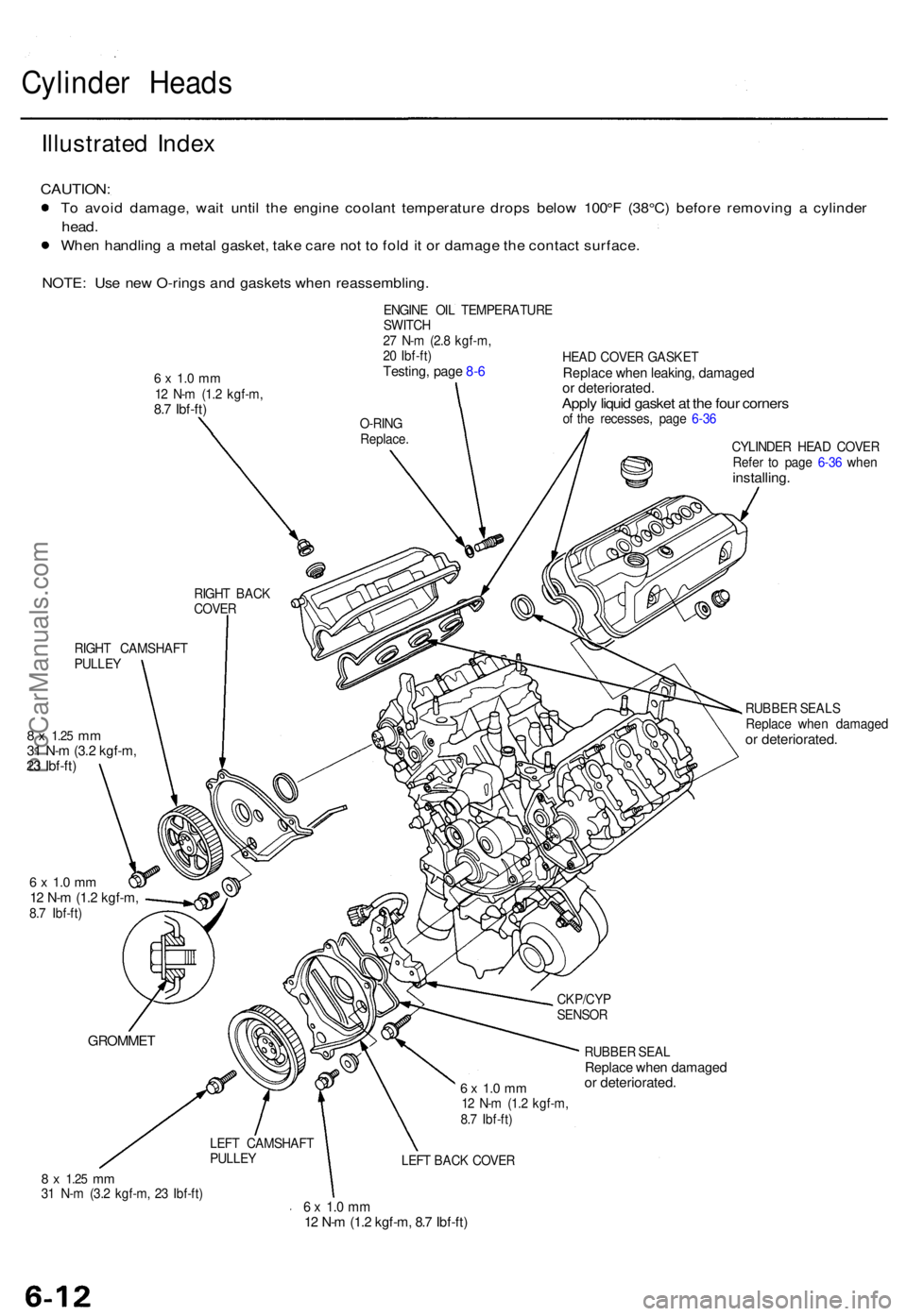
Cylinder Head s
Illustrate d Inde x
CAUTION :
To avoi d damage , wai t unti l th e engin e coolan t temperatur e drop s belo w 100° F (38°C ) befor e removin g a cylinde r
head.
When handlin g a meta l gasket , tak e car e no t t o fol d it o r damag e th e contac t surface .
NOTE: Us e ne w O-ring s an d gasket s whe n reassembling .
6 x 1. 0 m m12 N- m (1. 2 kgf-m ,8.7 Ibf-ft )
RIGHT CAMSHAF T
PULLE Y
8 x 1.2 5 mm31 N- m (3. 2 kgf-m ,23 Ibf-ft )
6 x 1. 0 m m12 N- m (1. 2 kgf-m ,8.7 Ibf-ft ) ENGIN
E OI L TEMPERATUR E
SWITC H
2 7 N- m (2. 8 kgf-m ,
2 0 Ibf-ft )
Testing , pag e 8- 6HEA D COVE R GASKE TReplace whe n leaking , damage dor deteriorated .Apply liqui d gaske t a t th e fou r corner sof th e recesses , pag e 6-3 6
CYLINDE R HEA D COVE R
Refe r t o pag e 6-3 6 whe n
installing .
RUBBER SEAL S
Replac e whe n damage d
or deteriorated .
GROMMET
6 x 1. 0 m m12 N- m (1. 2 kgf-m ,
8. 7 Ibf-ft ) RUBBE
R SEA L
Replac e whe n damage dor deteriorated .
LEFT BAC K COVE R
8 x 1.2 5 mm31 N- m (3. 2 kgf-m , 2 3 Ibf-ft )6 x 1. 0 m m12 N- m (1. 2 kgf-m , 8. 7 Ibf-ft )
LEFT CAMSHAF T
PULLE Y CKP/CY
P
SENSO R
RIGH
T BAC K
COVE R O-RIN
G
Replace .
ProCarManuals.com
Page 130 of 1771
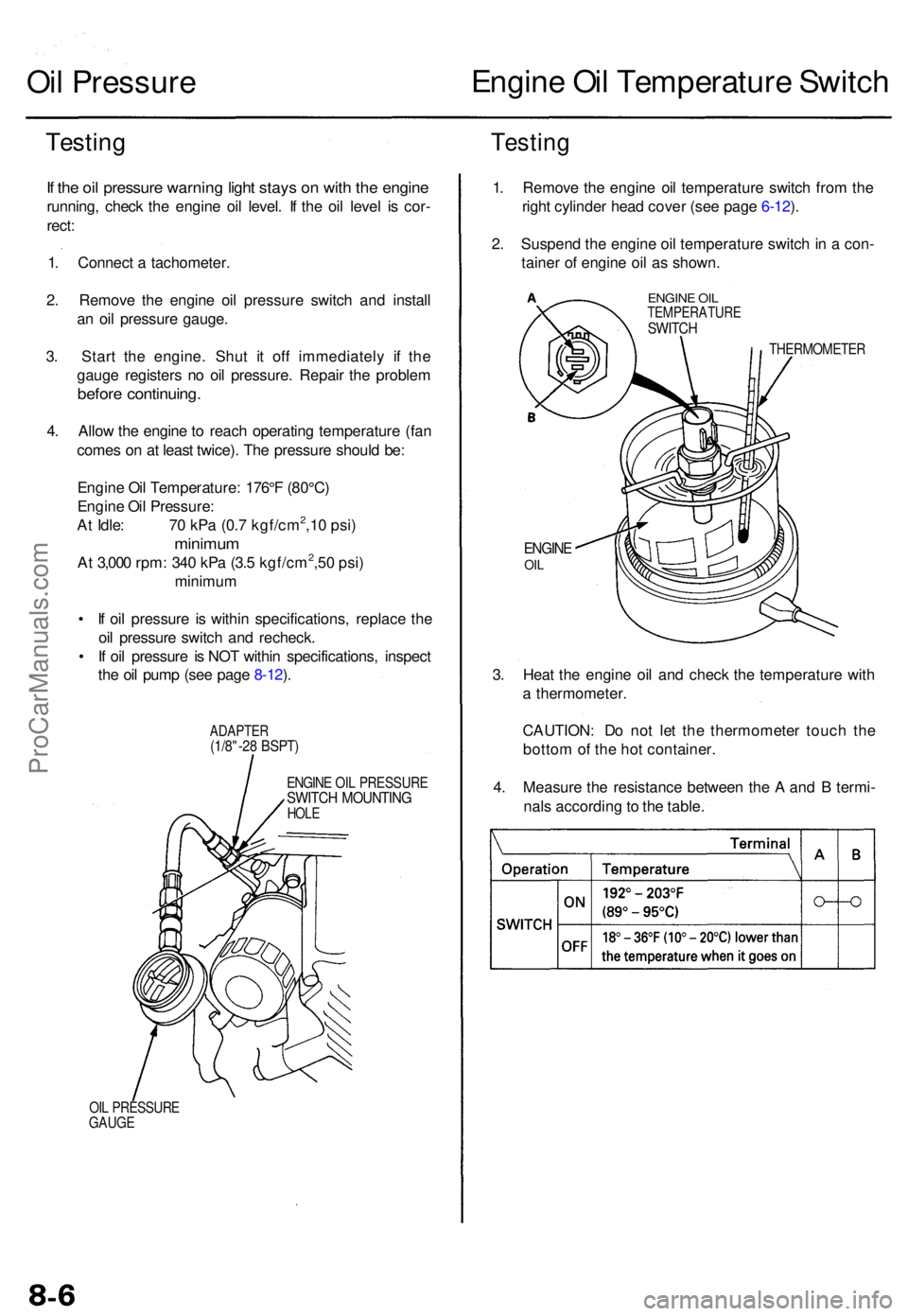
Oil Pressur e Engin
e Oi l Temperatur e Switc h
Testin gTestin g
If th e oi l pressur e warnin g ligh t stay s o n wit h th e engin e
running , chec k th e engin e oi l level . I f th e oi l leve l i s cor -
rect :
1 . Connec t a tachometer .
2 . Remov e th e engin e oi l pressur e switc h an d instal l
a n oi l pressur e gauge .
3 . Star t th e engine . Shu t i t of f immediatel y i f th e
gaug e register s n o oi l pressure . Repai r th e proble m
before continuing .
4. Allo w th e engin e to reac h operatin g temperatur e (fa n
come s o n a t leas t twice) . Th e pressur e shoul d be :
Engin e Oi l Temperature : 176° F (80°C )
Engin e Oi l Pressure :
A t Idle : 7 0 kP a (0. 7 kgf/cm
2,1 0 psi )
minimu m
At 3,00 0 rpm : 34 0 kP a (3. 5 kgf/cm2,5 0 psi )
minimu m
• I f oi l pressur e i s withi n specifications , replac e th e
oi l pressur e switc h an d recheck .
• I f oi l pressur e i s NO T withi n specifications , inspec t
th e oi l pum p (se e pag e 8-12 ).
ADAPTE R(1/8"-28 BSPT )
ENGIN E OI L PRESSUR ESWITCH MOUNTIN GHOLE
OIL PRESSUR E
GAUG E
1. Remov e th e engin e oi l temperatur e switc h fro m th e
righ t cylinde r hea d cove r (se e pag e 6-12 ).
2 . Suspen d th e engin e oi l temperatur e switc h in a con -
taine r o f engin e oi l a s shown .
ENGINE OI LTEMPERATUR ESWITCH
THERMOMETE R
ENGINEOIL
3. Hea t th e engin e oi l an d chec k th e temperatur e wit h
a thermometer .
CAUTION : D o no t le t th e thermomete r touc h th e
botto m of th e ho t container .
4 . Measur e th e resistanc e betwee n th e A an d B termi -
nal s accordin g to th e table .
ProCarManuals.com
Page 141 of 1771
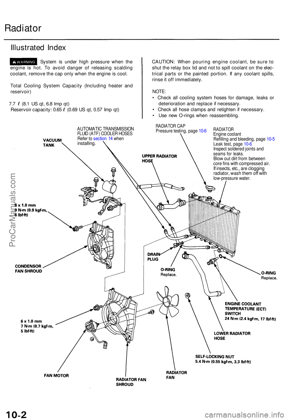
Radiator
Illustrate d Inde x
Syste m is unde r hig h pressur e whe n th e
engin e i s hot . T o avoi d dange r o f releasin g scaldin g
coolant , remov e th e ca p onl y whe n th e engin e is cool .
Tota l Coolin g Syste m Capacit y (Includin g heate r an d
reservoir )
7.7 (8. 1 US qt , 6. 8 Im p qt )
Reservoi r capacity : 0.6 5 (0.6 9 U S qt , 0.5 7 Im p qt ) CAUTION
: Whe n pourin g engin e coolant , b e sur e t o
shu t th e rela y bo x li d an d no t t o spil l coolan t o n th e elec -
trica l part s o r th e painte d portion . I f an y coolan t spills ,
rins e it of f immediately .
NOTE:
• Chec k al l coolin g syste m hose s fo r damage , leak s o r
deterioratio n an d replac e if necessary .
• Chec k al l hos e clamp s an d retighte n if necessary .
• Us e ne w O-ring s whe n reassembling .
RADIATOR CA PPressur e testing , pag e 10- 6RADIATO REngine coolan t
Refillin g an d bleeding , pag e 10- 5
Leak test , pag e 10- 6Inspec t soldere d joint s an dseam s fo r leaks .Blow ou t dir t fro m betwee ncore fin s wit h compresse d air .If insects , etc. , ar e cloggin gradiator , was h the m of f wit hlow-pressur e water .
AUTOMATI C TRANSMISSIO NFLUID (ATF ) COOLE R HOSE SRefer t o sectio n 1 4 whe ninstalling .
ProCarManuals.com
Page 145 of 1771
Radiator
Cap Testing
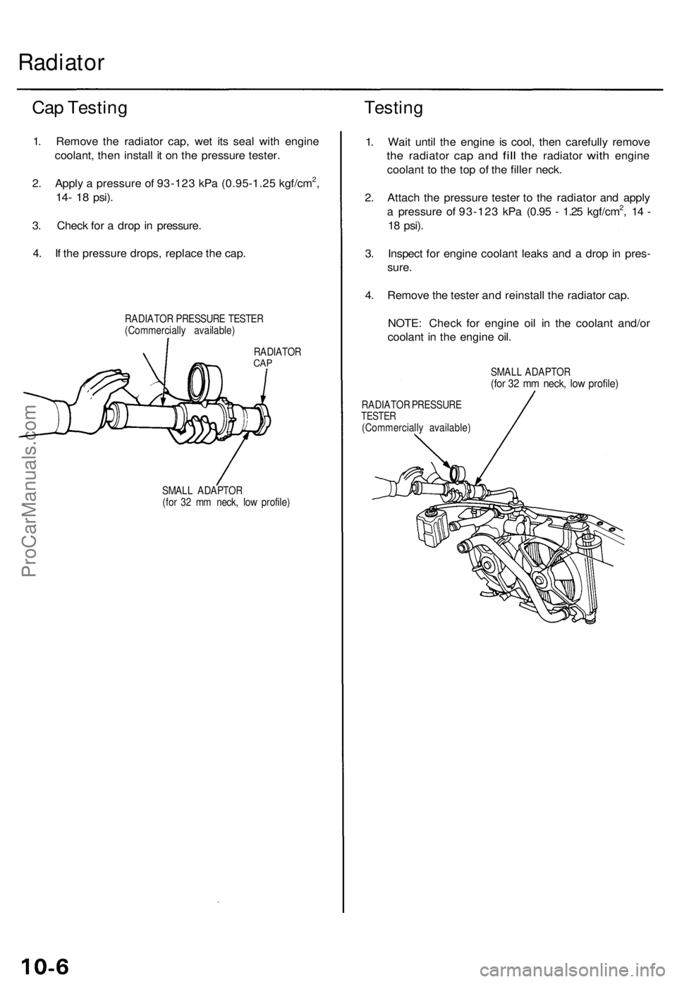
1. Remove the radiator cap, wet its seal with engine
coolant, then install it on the pressure tester.
2. Apply a pressure of 93-123 kPa (0.95-1.25 kgf/cm2,
14- 18
psi).
3. Check for a drop in pressure.
4. If the pressure drops, replace the cap.
RADIATOR PRESSURE TESTER
(Commercially available)
Testing
RADIATOR
CAP
SMALL ADAPTOR
(for 32 mm neck, low profile)
1. Wait until the engine is cool, then carefully remove
the
radiator
cap and
fill
the
radiator
with
engine
coolant to the top of the filler neck.
2. Attach the pressure tester to the radiator and apply
a pressure of 93-123 kPa (0.95 - 1.25 kgf/cm2, 14 -
18
psi).
3. Inspect for engine coolant leaks and a drop in pres-
sure.
4. Remove the tester and reinstall the radiator cap.
NOTE: Check for engine oil in the coolant and/or
coolant in the engine oil.
SMALL ADAPTOR
(for 32 mm neck, low profile)
RADIATOR PRESSURE
TESTER
(Commercially available)ProCarManuals.com
Page 147 of 1771
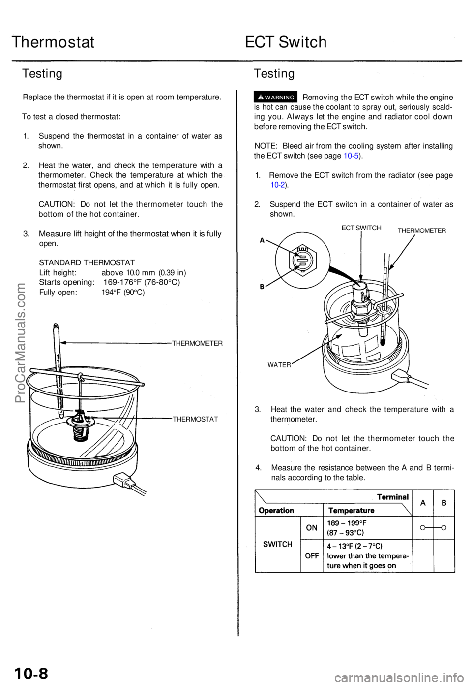
Thermostat ECT Switc h
Testin g
Replac e th e thermosta t i f i t i s ope n a t roo m temperature .
T o tes t a close d thermostat :
1 . Suspen d th e thermosta t i n a containe r o f wate r a s
shown .
2 . Hea t th e water , an d chec k th e temperatur e wit h a
thermometer . Chec k th e temperatur e a t whic h th e
thermosta t firs t opens , an d a t whic h i t i s full y open .
CAUTION : D o no t le t th e thermomete r touc h th e
botto m o f th e ho t container .
3. Measur e lif t heigh t o f th e thermosta t whe n it i s full y
open .
STANDAR D THERMOSTA T
Lif t height : abov e 10. 0 m m (0.3 9 in )
Start s opening : 169-176° F (76-80°C )
Fully open : 194° F (90°C )
THERMOMETE R
THERMOSTAT
Testing
Removin g th e EC T switc h whil e th e engin e
is ho t ca n caus e th e coolan t t o spra y out , seriousl y scald -
ing you . Alway s le t th e engin e an d radiato r coo l dow n
befor e removin g th e EC T switch .
NOTE : Blee d ai r fro m th e coolin g syste m afte r installin g
th e EC T switc h (se e pag e 10-5 ).
1 . Remov e th e EC T switc h fro m th e radiato r (se e pag e
10-2).
2 . Suspen d th e EC T switc h i n a containe r o f wate r a s
shown .
ECT SWITC HTHERMOMETE R
WATER
3. Hea t th e wate r an d chec k th e temperatur e wit h a
thermometer .
CAUTION : D o no t le t th e thermomete r touc h th e
botto m of th e ho t container .
4 . Measur e th e resistanc e betwee n th e A an d B termi -
nal s accordin g t o th e table .
ProCarManuals.com
Page 152 of 1771
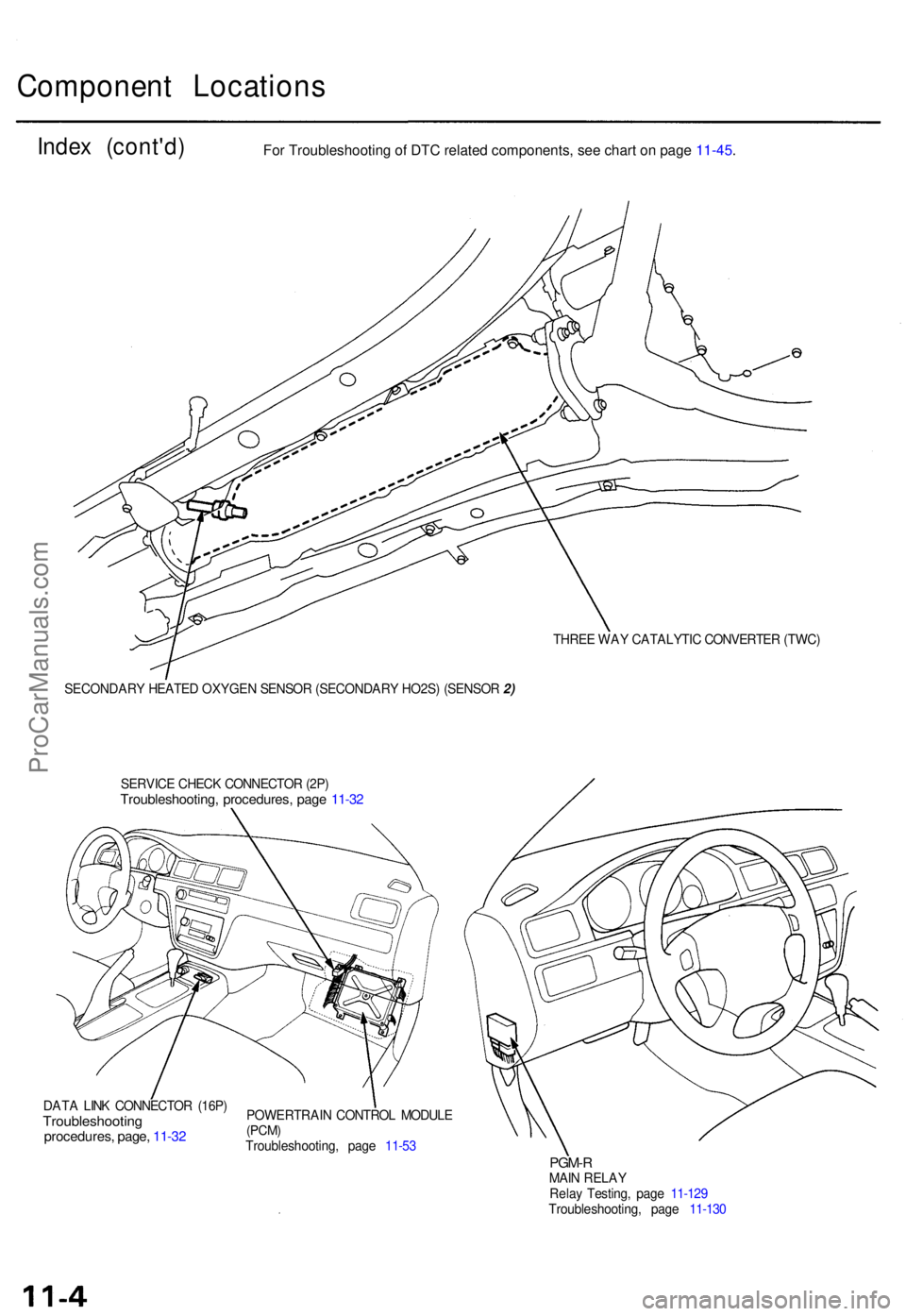
Component Location s
Index (cont'd )
THREE WA Y CATALYTI C CONVERTE R (TWC )
SECONDAR Y HEATE D OXYGE N SENSO R (SECONDAR Y HO2S ) (SENSO R 2)
SERVIC E CHEC K CONNECTO R (2P )
Troubleshooting , procedures , pag e 11-3 2
DAT A LIN K CONNECTO R (16P )Troubleshootin gprocedures, page , 11-3 2
POWERTRAI N CONTRO L MODUL E(PCM)Troubleshooting , pag e 11-5 3
PGM- RMAIN RELA Y
Rela y Testing , pag e 11-12 9
Troubleshooting , pag e 11-13 0
For Troubleshooting of DTC related components, see chart on page 11-45.
ProCarManuals.com
Page 154 of 1771
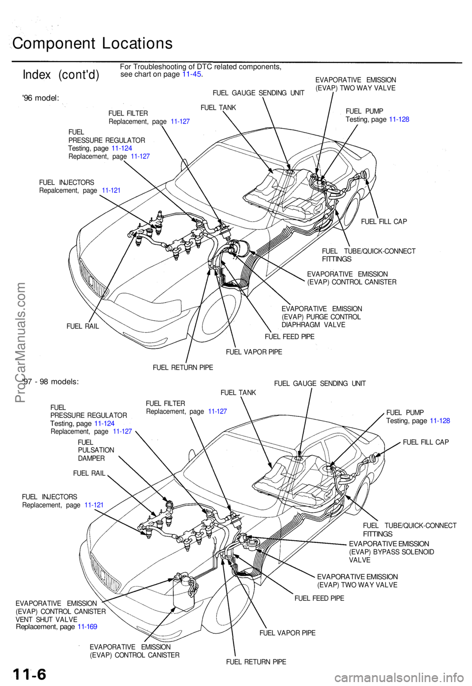
Component Location s
Index (cont'd )
'96 model :
EVAPORATIV E EMISSIO N
(EVAP ) TW O WA Y VALV E
FUE L INJECTOR S
Repalcement , pag e 11-12 1 FUE
L PUM P
Testing , pag e 11-12 8
FUEL FIL L CA P
FUE L RAI L FUE
L TUBE/QUICK-CONNEC T
FITTINGS
EVAPORATIV E EMISSIO N
(EVAP ) CONTRO L CANISTE R
EVAPORATIV E EMISSIO N
(EVAP ) PURG E CONTRO L
DIAPHRAG M VALV E
FUE L FEE D PIP E
FUE L VAPO R PIP E
FUE L RETUR N PIP E
'97 - 9 8 models :FUEL GAUG E SENDIN G UNI T
FUE L TAN K
FUE L
PRESSUR E REGULATO R
Testing, pag e 11-12 4Replacement , pag e 11-12 7
FUE L
PULSATIO N
DAMPE R
FUE L RAI L FUE
L FILTE R
Replacement , pag e 11-12 7
FUE L INJECTOR S
Replacement , pag e 11-12 1
EVAPORATIV E EMISSIO N
(EVAP ) CONTRO L CANISTE R
VEN T SHU T VALV E
Replacement , pag e 11-16 9
FUEL PUM PTesting , pag e 11-12 8
FUEL FIL L CA P
FUE L TUBE/QUICK-CONNEC T
FITTINGS
EVAPORATIV E EMISSIO N(EVAP) BYPAS S SOLENOI D
VALV E
EVAPORATIV E EMISSIO N(EVAP) TW O WA Y VALV E
FUE L FEE D PIP E
FUE L VAPO R PIP E
EVAPORATIV E EMISSIO N
(EVAP ) CONTRO L CANISTE R
FUEL RETUR N PIP E
FUE
L FILTE R
Replacement , pag e 11-12 7FUE
L TAN K
FUE L
PRESSUR E REGULATO R
Testing, pag e 11-12 4Replacement , pag e 11-12 7 FUE
L GAUG E SENDIN G UNI T
For Troubleshooting of DTC related components,
see chart on page 11-45.
ProCarManuals.com
Page 180 of 1771

Troubleshooting
Troubleshooting Procedure s
I. Ho w T o Begi n Troubleshootin g
Whe n th e Malfunctio n Indicato r Lam p (MIL ) ha s bee n reporte d on , o r ther e i s a driveabilit y problem , us e th e appropri -
at e procedur e belo w to diagnos e an d repai r th e problem .
A . Whe n th e MI L ha s com e on :
1 . Connec t th e Hond a PG M Teste r o r a n OB D II sca n too l t o th e 16 P Dat a Lin k Connecto r (DLC ) locate d o n th e cente r
consol e behin d th e ashtray .
2 . Tur n th e ignitio n switc h O N (II) .
3 . Chec k th e DT C an d not e it . Als o chec k an d not e th e
freez e fram e data .
Refe r t o th e Diagnosti c Troubl e Cod e Char t an d
begi n troubleshooting .
MALFUNCTIONINDICATORLAMP(MIL)
NOTE :
See th e OB D II sca n too l o r Hond a PG M Teste r user' s manual s fo r specifi c operatin g instructions .
Th e sca n too l o r teste r ca n rea d th e Diagnosti c Troubl e Code s (DTC) , freez e fram e data , curren t data , an d othe r
Powertrai n Contro l Modul e (PCM ) data .
Freez e fram e dat a indicate s th e engin e condition s whe n th e firs t malfunction , misfir e o r fue l tri m malfunctio n wa s
detected . I t ca n b e usefu l informatio n whe n troubleshooting .
B . Whe n th e MI L ha s no t com e on , bu t ther e is a driveabilit y problem , refe r t o th e Sympto m Char t o n pag e 11-34 .
C . DTC s wil l b e indicate d b y th e blinkin g o f th e Malfunctio n Indicato r Lam p (MIL ) wit h th e SC S servic e connecto r
connected .
• Connec t th e SC S servic e connecto r t o Servic e Chec k Connecto r a s shown . (Th e 2 P Servic e Chec k Connecto r
i s locate d unde r th e das h o n th e passenger' s sid e o f th e car. ) Tur n th e ignitio n switc h O N (II) .
DAT A LIN K CONNECTO R (16P )SERVIC E CHEC KCONNECTO R (2P )
OBD II SCA N TOO L o rHOND A PG M TESTE R
SCS SERVIC E CONNECTO R07PAZ-001010 0
ProCarManuals.com