Page 271 of 1771
Position, 4th gear
1. The hydraulic pressure is applied to the 4th clutch, which rotates together with the mainshaft, and the mainshaft 4th
gear rotates.
2. Power is transmitted to the countershaft 4th gear, which drives the countershaft.
3. Power is transmitted to the secondary drive gear, which drives the secondary driven gear.
NOTE: In
position, 4th gear, hydraulic pressure is also applied to the 1st clutch and to the 2nd clutch, but since the
rotation speed of 4th gear exceeds that of 2nd gear, power from 2nd gear is cut off at the 2nd gear one-way clutch.
MAINSHAFT
2ND GEAR
2ND CLUTCH
MAINSHAFT
TORQUE CONVERTER
MAINSHAFT
4TH GEAR
1ST CLUTCH
4TH CLUTCH
COUNTERSHAFT
4TH GEAR
COUNTERSHAFT
2ND GEAR
2ND GEAR
ONE-WAY CLUTCH
COUNTERSHAFT
SECONDARY
DRIVE GEAR
SECONDARY DRIVEN GEAR
(cont'd)ProCarManuals.com
Page 272 of 1771
Description
Power Flow (cont'd)
Position
1. The hydraulic pressure is applied to the reverse clutch. Power is transmitted from the mainshaft reverse gear via the
reverse idler gear to the countershaft reverse gear.
2. The rotation direction of the countershaft reverse gear is changed via the reverse idler gear in the rear cover.
3. Power is transmitted to the secondary drive gear, which drives the secondary driven gear.
REVERSE IDLER
GEAR
TORQUE CONVERTER
MAINSHAFT REVERSE
GEAR
COUNTERSHAFT
REVERSE GEAR
MAINSHAFT
REVERSE GEAR
REVERSE
IDLER GEAR
MAINSHAFT
COUNTERSHAFT
COUNTERSHAFT
REVERSE GEAR
REVERSE CLUTCH
SECONDARY DRIVEN GEAR
SECONDARY
DRIVE GEARProCarManuals.com
Page 277 of 1771
Description
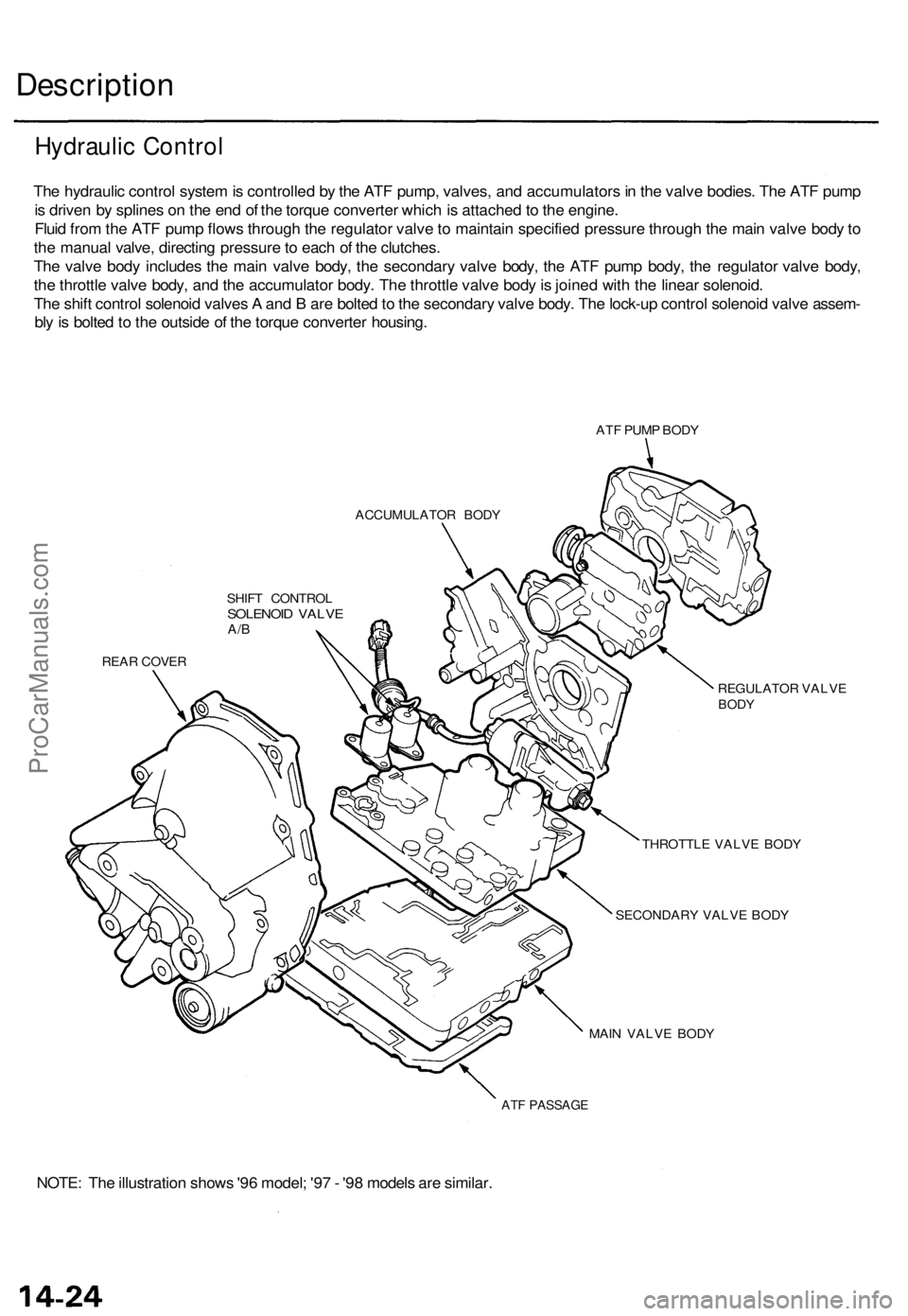
The hydraulic control system is controlled by the ATF pump, valves, and accumulators in the valve bodies. The ATF pump
is driven by splines on the end of the torque converter which is attached to the engine.
Fluid from the ATF pump flows through the regulator valve to maintain specified pressure through the main valve body to
the manual valve, directing pressure to each of the clutches.
The valve body includes the main valve body, the secondary valve body, the ATF pump body, the regulator valve body,
the throttle valve body, and the accumulator body. The throttle valve body is joined with the linear solenoid.
The shift control solenoid valves A and B are bolted to the secondary valve body. The lock-up control solenoid valve assem-
bly is bolted to the outside of the torque converter housing.
ATF PUMP BODY
ACCUMULATOR BODY
SHIFT CONTROL
SOLENOID VALVE
A/B
REAR COVER
REGULATOR VALVE
BODY
THROTTLE VALVE BODY
SECONDARY VALVE BODY
MAIN VALVE BODY
ATF PASSAGE
NOTE: The illustration shows '96 model; '97 - '98 models are similar.
Hydraulic ControlProCarManuals.com
Page 278 of 1771
Hydraulic Control/Lower Valve Body Assembly — '96 Model
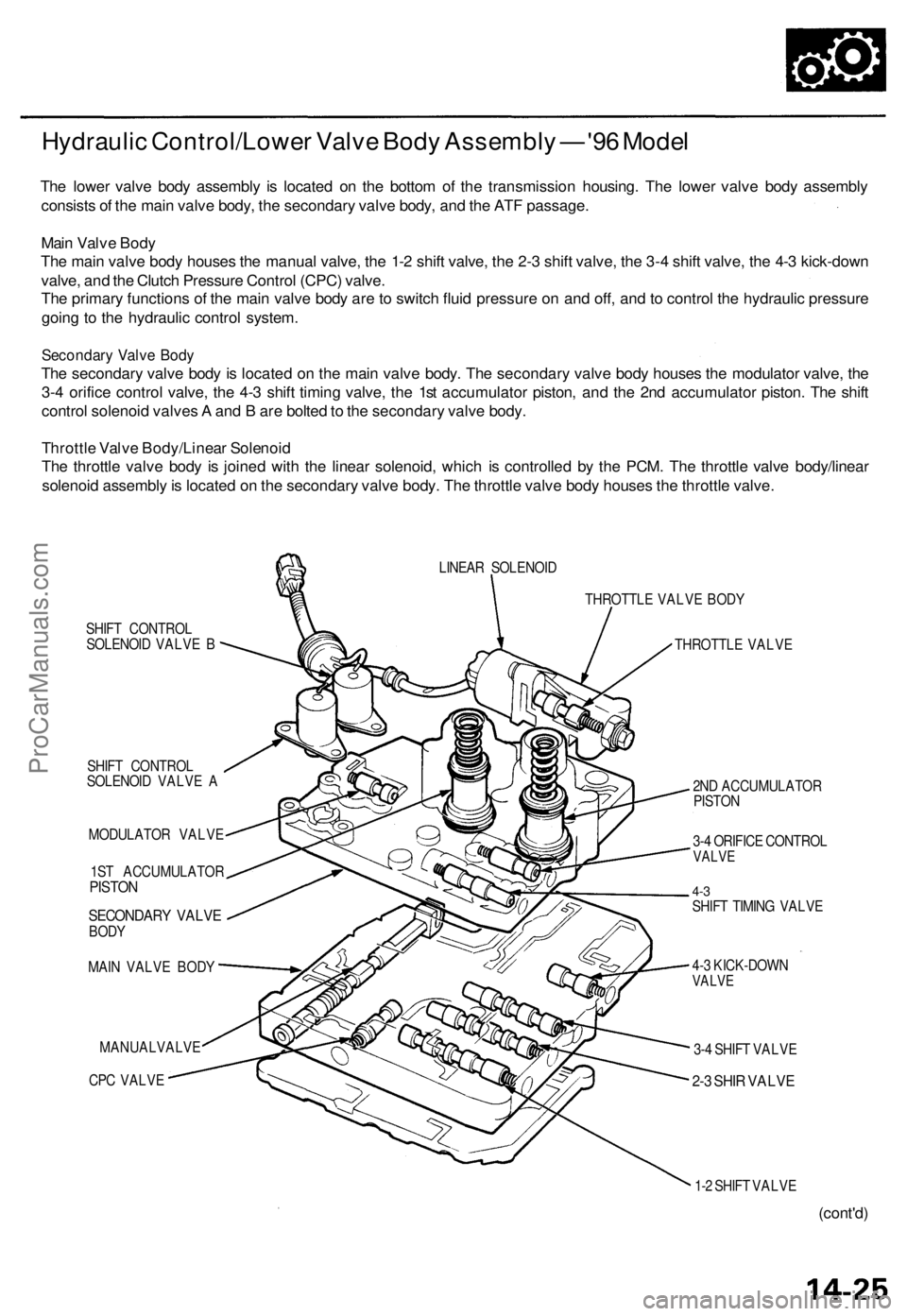
The lower valve body assembly is located on the bottom of the transmission housing. The lower valve body assembly
consists of the main valve body, the secondary valve body, and the ATF passage.
Main Valve Body
The main valve body houses the manual valve, the 1-2 shift valve, the 2-3 shift valve, the 3-4 shift valve, the 4-3 kick-down
valve, and the Clutch Pressure Control (CPC) valve.
The primary functions of the main valve body are to switch fluid pressure on and off, and to control the hydraulic pressure
going to the hydraulic control system.
Secondary Valve Body
The secondary valve body is located on the main valve body. The secondary valve body houses the modulator valve, the
3-4 orifice control valve, the 4-3 shift timing valve, the 1st accumulator piston, and the 2nd accumulator piston. The shift
control solenoid valves A and B are bolted to the secondary valve body.
Throttle Valve Body/Linear Solenoid
The throttle valve body is joined with the linear solenoid, which is controlled by the PCM. The throttle valve body/linear
solenoid assembly is located on the secondary valve body. The throttle valve body houses the throttle valve.
SHIFT CONTROL
SOLENOID VALVE B
SHIFT CONTROL
SOLENOID VALVE A
MODULATOR VALVE
1ST ACCUMULATOR
PISTON
SECONDARY VALVE
BODY
MAIN VALVE BODY
MANUALVALVE
CPC VALVE
LINEAR SOLENOID
THROTTLE VALVE BODY
THROTTLE VALVE
2ND ACCUMULATOR
PISTON
3-4 ORIFICE CONTROL
VALVE
4-3
SHIFT TIMING VALVE
4-3 KICK-DOWN
VALVE
3-4 SHIFT VALVE
2-3 SHIR VALVE
1-2 SHIFT VALVE
(cont'd)ProCarManuals.com
Page 284 of 1771
Position
(cont'd)
As the engine turns, the ATF pump also starts to operate. Automatic transmission fluid (ATF) is drawn from (99) and dis-
charged into (1). Then, ATF flowing from the ATF pump becomes the line pressure (1). The line pressure (1) is regulated
by the regulator valve. The torque converter inlet pressure (92) enters (94) of the torque converter through the lock-up
shift valve and discharges into (90).
The torque converter check valve prevents the torque converter pressure from rising.
Under this condition, the hydraulic pressure is not applied to the clutches as the manual valve stops line pressure (1).
NOTE: When used, "left" or "right" indicates direction on the hydraulic circuit.ProCarManuals.com
Page 285 of 1771
Description
Hydraulic Flo w — '9 6 Mode l (cont'd )
Position
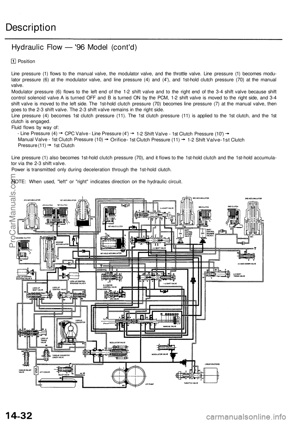
Lin e pressur e (1 ) flow s t o th e manua l valve , th e modulato r valve , an d th e throttl e valve . Lin e pressur e (1 ) become s modu -
lato r pressur e (6 ) a t th e modulato r valve , an d lin e pressur e (4 ) an d
(4') , and 1st-hol d clutc h pressur e (70 ) a t th e manua l
valve .
Modulato r pressur e (6 ) flow s t o th e lef t en d o f th e 1- 2 shif t valv e an d t o th e righ t en d o f th e 3- 4 shif t valv e becaus e shif t
contro l solenoi d valv e A is turne d OF F an d B is turne d O N b y th e PCM , 1- 2 shif t valv e i s move d t o th e righ t side , an d 3- 4
shif t valv e i s move d t o th e lef t side . Th e 1st-hol d clutc h pressur e (70 ) become s lin e pressur e (7 ) a t th e manua l valve , the n
goe s t o th e 2- 3 shif t valve . Th e 2- 3 shif t valv e remain s i n th e righ t side .
Lin e pressur e (4 ) become s 1s t clutc h pressur e (11) . Th e 1s t clutc h pressur e (11 ) i s applie d t o th e 1s t clutch , an d th e 1s t
clutc h i s engaged .
Flui d flow s b y wa y of :
Lin e pressur e (1 ) als o become s 1st-hol d clutc h pressur e (70) , an d it flow s t o th e 1st-hol d clutc h an d th e 1st-hol d accumula -
to r vi a th e 2- 3 shif t valve .
Powe r i s transmitte d onl y durin g deceleratio n throug h th e 1st-hol d clutch .
NOTE : Whe n used , "left " o r "right " indicate s directio n o n th e hydrauli c circuit .
-
Lin e Pressur e (4 )
CPC Valv e - Lin e Pressur e
(4')
Manua l Valv e - 1s t Clutc h Pressur e (10 )
Pressur e
(11) 1s t Clutc h
Orifice - 1st Clutc h Pressur e (11 )
1-
2 Shif t Valv e - 1s t Clutc h Pressur e
(10')
1-2 Shif t Valve-1s t Clutch
ProCarManuals.com
Page 286 of 1771
Position
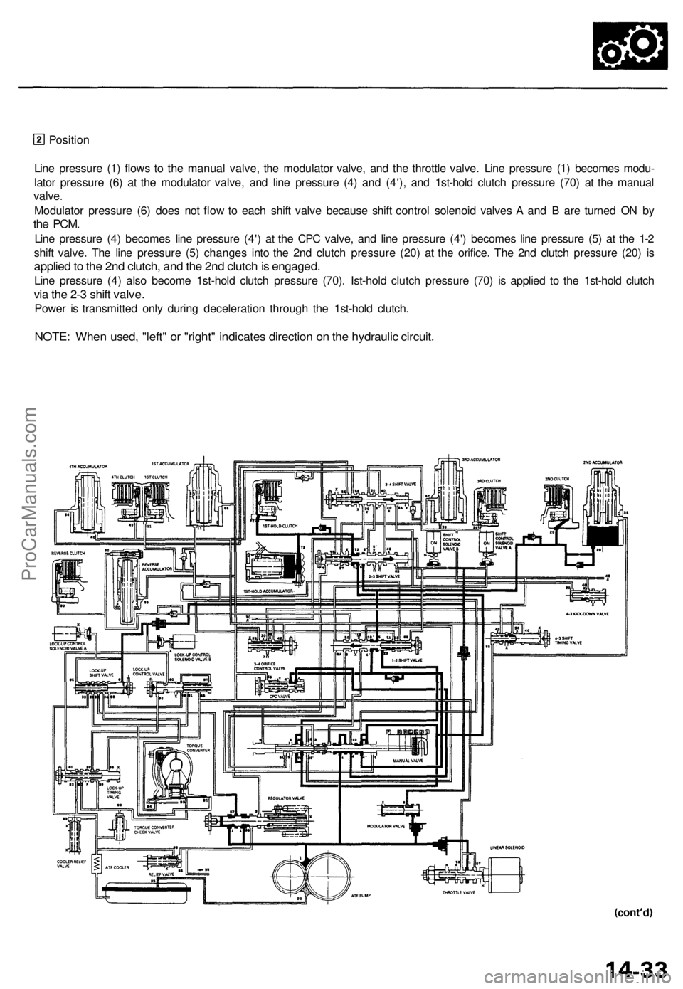
Line pressure (1) flows to the manual valve, the modulator valve, and the throttle valve. Line pressure (1) becomes modu-
lator pressure (6) at the modulator valve, and line pressure (4) and (4'), and 1st-hold clutch pressure (70) at the manual
valve.
Modulator pressure (6) does not flow to each shift valve because shift control solenoid valves A and B are turned ON by
the
PCM.
Line pressure (4) becomes line pressure (4') at the CPC valve, and line pressure (4') becomes line pressure (5) at the 1-2
shift valve. The line pressure (5) changes into the 2nd clutch pressure (20) at the orifice. The 2nd clutch pressure (20) is
applied to the 2nd clutch, and the 2nd clutch is engaged.
Line pressure (4) also become 1st-hold clutch pressure (70). Ist-hold clutch pressure (70) is applied to the 1st-hold clutch
via the 2-3 shift valve.
Power is transmitted only during deceleration through the 1st-hold clutch.
NOTE: When used, "left" or "right" indicates direction on the hydraulic circuit.ProCarManuals.com
Page 287 of 1771
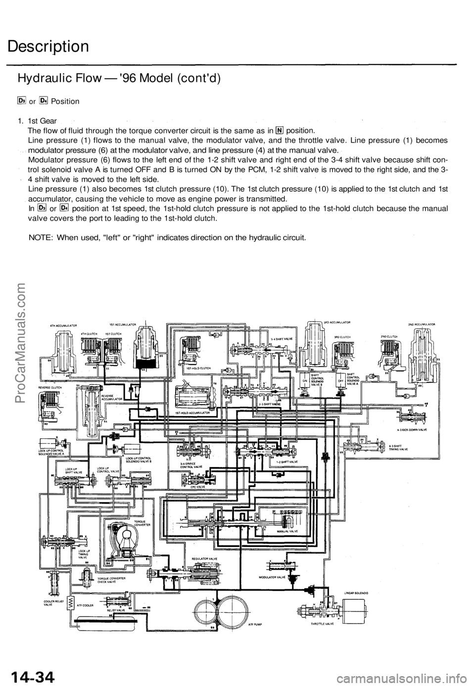
Description
Hydraulic Flow — '96 Model (cont'd)
or
Position
NOTE: When used, "left" or "right" indicates direction on the hydraulic circuit.
1. 1st Gear
Line pressure (1) flows to the manual valve, the modulator valve, and the throttle valve. Line pressure (1) becomes
modulator pressure (6) at the modulator valve, and line pressure (4) at the manual valve.
Modulator pressure (6) flows to the left end of the 1-2 shift valve and right end of the 3-4 shift valve because shift con-
trol solenoid valve A is turned OFF and B is turned ON by the PCM, 1-2 shift valve is moved to the right side, and the 3-
4 shift valve is moved to the left side.
Line pressure (1) also becomes 1st clutch pressure (10). The 1st clutch pressure (10) is applied to the 1st clutch and 1st
accumulator, causing the vehicle to move as engine power is transmitted.
valve covers the port to leading to the 1st-hold clutch.
position.
The flow of fluid through the torque converter circuit is the same as in
In
or
position at 1st speed, the 1st-hold clutch pressure is not applied to the 1st-hold clutch because the manualProCarManuals.com