Page 727 of 1771

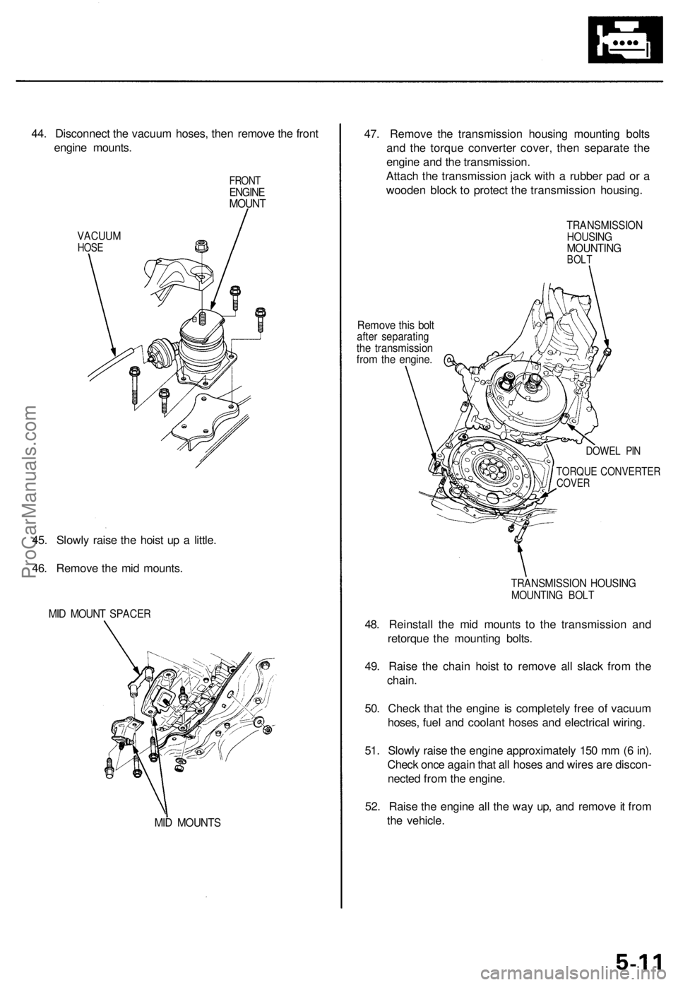
44. Disconnect the vacuum hoses, then remove the front
engine mounts.
VACUUM
HOSE
FRONT
ENGINE
MOUNT
45. Slowly raise the hoist up a little.
46. Remove the mid mounts.
MID MOUNT SPACER
MID MOUNTS
47. Remove the transmission housing mounting bolts
and the torque converter cover, then separate the
engine and the transmission.
Attach the transmission jack with a rubber pad or a
wooden block to protect the transmission housing.
Remove this bolt
after separating
the transmission
from the engine.
TRANSMISSION
HOUSING
MOUNTING
BOLT
DOWEL PIN
TORQUE CONVERTER
COVER
TRANSMISSION HOUSING
MOUNTING BOLT
48. Reinstall the mid mounts to the transmission and
retorque the mounting bolts.
49. Raise the chain hoist to remove all slack from the
chain.
50. Check that the engine is completely free of vacuum
hoses, fuel and coolant hoses and electrical wiring.
51. Slowly raise the engine approximately 150 mm (6 in).
Check once again that all hoses and wires are discon-
nected from the engine.
52. Raise the engine all the way up, and remove it from
the vehicle.ProCarManuals.com
Page 1491 of 1771

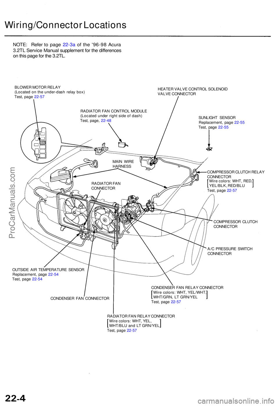
Wiring/Connector Location s
BLOWER MOTO R RELA Y
(Locate d o n th e under-das h rela y box )
Test , pag e 22-5 7 HEATE
R VALV E CONTRO L SOLENOI D
VALV E CONNECTO R
SUNLIGH T SENSO R
Replacement , pag e 22-5 5
Test , pag e 22-5 5
COMPRESSO R CLUTC H RELA Y
CONNECTO R
Wir e colors : WHT , RED ,
YEL/BLK , RED/BL U
Test , pag e 22-5 7
COMPRESSO R CLUTC H
CONNECTO R
A/ C PRESSUR E SWITC H
CONNECTO R
OUTSID E AI R TEMPERATUR E SENSO R
Replacement , pag e 22-5 4
Test , pag e 22-5 4
CONDENSE R FA N CONNECTO R CONDENSE
R FA N RELA Y CONNECTO R
Wir e colors : WHT , YEL/WHT ,
WHT/GRN, L T GRN/YE L
Test , pag e 22-5 7
RADIATO R FA N RELA Y CONNECTO R
Wir e colors : WHT , YEL ,
WHT/BL U an d L T GRN/YE L
Test , pag e 22-5 7
RADIATO
R FA N
CONNECTO RMAI
N WIR E
HARNES S
RADIATO R FA N CONTRO L MODUL E
(Locate d unde r righ t sid e o f dash )
Test , page , 22-4 8
NOTE : Refe r t o page 22-3a of the '96-9 8 Acura
3.2TL Servic e Manual supplement for the differences
on this page for the 3.2TL.
ProCarManuals.com
Page 1536 of 1771

Troubleshooting
Tips and Precautions
Before Troubleshooting
Check applicable fuses in the appropriate fuse/relay
box.
Check the battery for damage, state of charge, and
clean and tight connections.
Check the alternator belt tension.
CAUTION:
Do not quick-charge a battery unless the battery
ground cable has been disconnected, otherwise you
will damage the alternator diodes.
Do not attempt to crank the engine with the battery
ground cable loosely connected or you will severely
damage the wiring.
Handling Connectors
Make sure the connectors are clean and have no loose
wire terminals.
Make sure multiple cavity connectors are packed with
grease (except waterproof connectors).
All connectors have push-down release type locks.
LOCKING TAB
Some connectors have a clip on their side used to
attach them to a mount bracket on the body or on
another component. This clip has a pull type lock.
Some mounted connectors cannot be disconnected
unless you first release the lock and remove the con-
nector from its mount bracket.
LOCKING
PAWL ON
OTHER
HALF OF
CONNECTOR
Pull to
disengage
BRACKET
Never try to disconnect connectors by pulling on
their wires; pull on the connector halves instead.
Always reinstall plastic covers.
Before connecting connectors, make sure the termi-
nals are in place and not bent.
BENT TERMINAL
Check for loose retainer and rubber seals.
RETAINER
RUBBER SEAL RETAINER
The backs of some connectors are packed with
grease. Add grease if necessary. If the grease is con-
taminated, replace it.
LOCKING TABProCarManuals.com
Page 1738 of 1771

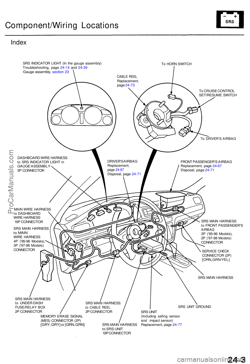
Component/Wiring Location s
Index
SRS INDICATO R LIGH T (I n th e gaug e assembly )
Troubleshooting , pag e 24-1 4 an d 24-3 9
Gaug e assembly , sectio n 2 3
To HOR N SWITC H
DASHBOAR D WIR E HARNES S
t o SR S INDICATO R LIGH T in
GAUG E ASSEMBL Y
5 P CONNECTO R
To DRIVER' S AIRBA G
FRONT PASSENGER' S AIRBA G
Replacement , pag e 24-6 7
Disposal , pag e 24-7 1
T
o CRUIS E CONTRO L
SET/RESUM E SWITC H
MAI N WIR E HARNES S
t o DASHBOAR D
WIR E HARNES S
16 P CONNECTO R
SR S MAI N HARNES S
to MAI NWIRE HARNES S
4 P ('95-9 6 Models) ,
3 P ('97-9 8 Models )
CONNECTO R SR
S MAI N HARNES S
t o FRON T PASSENGER' S
AIRBAG3P ('95-9 6 Models) ,
2 P ('97-9 8 Models )
CONNECTO R
SERVICE CHEC KCONNECTO R (2P )
[ORN , GRN/YEL ]
SR S MAI N HARNES S
SR S MAI N HARNES S
t o UNDER-DAS H
FUSE/RELAY BO X2P CONNECTO R
MEMOR Y ERAS E SIGNA L
(MES ) CONNECTO R (2P )
[GRY , GRY ] or [GRN , GRN ]SRS MAI N HARNES Sto SR S UNI T18P CONNECTO R SR
S UNI T GROUN D
SRS UNI T(Includin g safin g senso r
an d impac t sensor )
Replacement , pag e 24-7 7
CABL E REE LReplacement ,
pag e 24-7 3
DRIVER' S AIRBA G
Replacement ,
page 24-67Disposal , pag e 24-7 1
SR S MAI N HARNES S
to CABL E REE L2P CONNECTO R
ProCarManuals.com
Page 1742 of 1771
Wiring Precaution s
• Neve r attemp t t o modify , splic e o r repai r SR S wiring .
NOTE : SR S wirin g ca n b e identifie d b y specia l yello w
oute r covering .
• B e sur e to instal l th e harnes s wire s s o tha t the y ar e no t
pinche d o r interferin g wit h othe r parts .
• Mak e sur e al l SR S groun d location s ar e clea n an d
ground s ar e securel y fastene d fo r optimu m metal-to -
meta l contact . Poo r groundin g ca n caus e intermitten t
problem s tha t ar e difficul t t o diagnose . Disconnectin
g th e SR S Connecto r a t th e Under-das h
Fuse/Relay Box :
CAUTION : Avoi d breakin g th e connector ; it' s double -
locked.
1. Firs t lif t th e connecto r li d wit h a thi n screwdriver , the n
pres s th e connecto r ta b down , an d pul l th e connecto r
out.
2. T o reinstal l th e connector , pus h it int o positio n unti l i t
clicks , the n clos e it s lid .
ProCarManuals.com
Page 1771 of 1771

SUPPLEMENTAL RESTRAINT SYSTEMThe Acura TL SRS includes a driver's airbag located in the steering wheel hub and a passenger's airbag located in the dashboard above
the glove box. Information necessary to safely service the SRS is included in this Service Manual. Items marked with an asterisk (*) on
the contents page include, or are located near, SRS components. Servicing, disassembling or replacing these items will require special
precautions and tools, and should therefore be done by an authorized Honda dealer.
WARNING
�To avoid rendering the SRS inoperative, which could lead to personal injury or death in the event of a severe frontal
collision, all SRS service work must be performed by an authorized Honda dealer.
�Improper service procedures, including incorrect removal and installation of the SRS, could lead to personal injury
caused by unintentional activation of the front airbags, seat belt tensioners, and side airbags ('99-01 models).
�Do not bump the SRS unit. Otherwise, the system may fail in a collision, or the airbags may deploy when the ignition
switch in ON (II).
�All SRS electrical wiring harnesses are covered with yellow insulation. Related components are located in the steering
column, front console, dashboard, dashboard lower panel, in the dashboard above the glove box. Do not use electrical
test equipment on these circuits.
NOTE: The original radio has a coded theft protection circuit. Be sure to get the customer's code number before
± disconnecting the battery.
± removing the No. 39 (10A) fuse from the under±hood fuse/relay box.
± removing the radio.
After service, reconnect power to the radio and turn it on. When the word ºCODEº is displayed, enter the customer's 5-digit code to restore
radio operation.
ProCarManuals.com