1995 ACURA TL radiator
[x] Cancel search: radiatorPage 610 of 1771
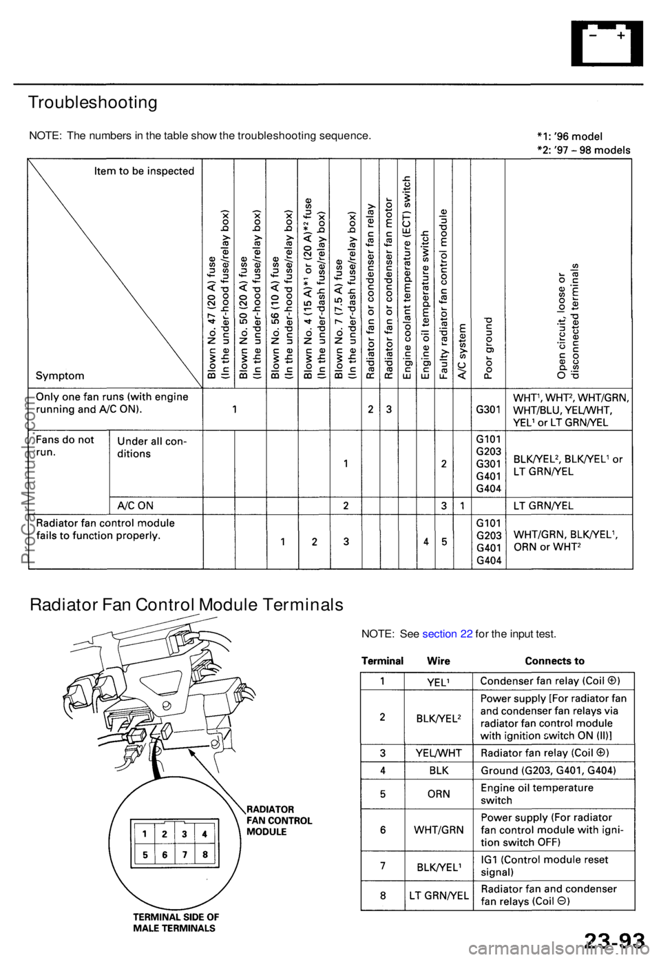
Troubleshooting
NOTE: Th e number s in th e tabl e sho w th e troubleshootin g sequence .
Radiator Fa n Contro l Modul e Terminal s
NOTE: Se e sectio n 2 2 fo r th e inpu t test .
ProCarManuals.com
Page 822 of 1771
Radiator
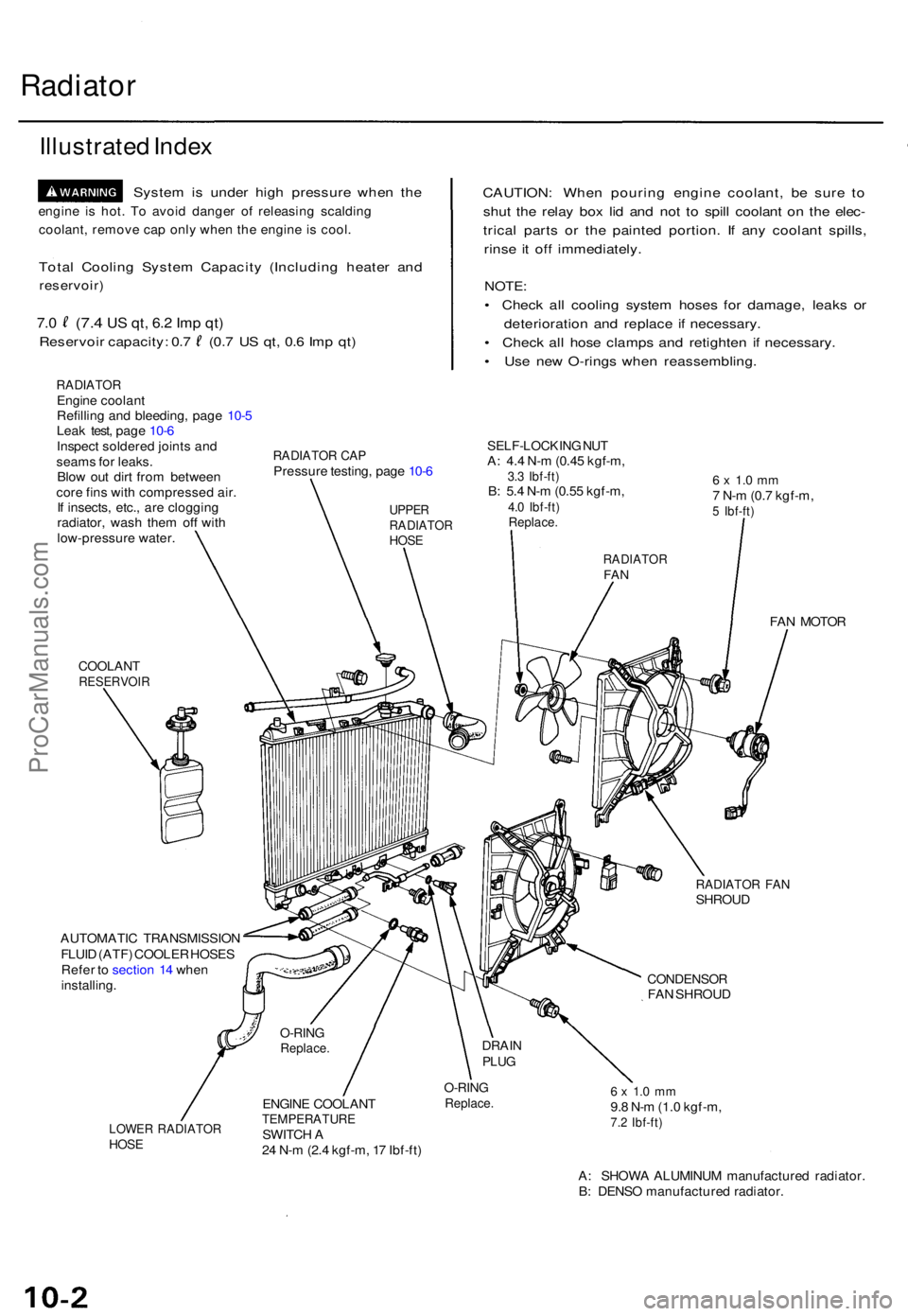
Illustrate d Inde x
Syste m is unde r hig h pressur e whe n th e
engin e i s hot . T o avoi d dange r o f releasin g scaldin g
coolant , remov e ca p onl y whe n th e engin e i s cool .
Total Coolin g Syste m Capacit y (Includin g heate r an d
reservoir )
7.0 (7. 4 US qt , 6. 2 Im p qt )
Reservoi r capacity : 0. 7 (0. 7 U S qt , 0. 6 Im p qt )
RADIATO REngine coolan t
Refillin g an d bleeding , pag e 10- 5
Lea k test , pag e 10- 6
Inspec t soldere d joint s an d
seam s fo r leaks .
Blo w ou t dir t fro m betwee n
cor e fin s wit h compresse d air .
I f insects , etc. , ar e cloggin g
radiator , was h the m of f wit h
low-pressur e water .
CAUTION : Whe n pourin g engin e coolant , b e sur e t o
shu t th e rela y bo x li d an d no t t o spil l coolan t o n th e elec -
trica l part s o r th e painte d portion . I f an y coolan t spills ,
rins e i t of f immediately .
NOTE:
• Chec k al l coolin g syste m hose s fo r damage , leak s o r
deterioratio n an d replac e i f necessary .
• Chec k al l hos e clamp s an d retighte n i f necessary .
• Us e ne w O-ring s whe n reassembling .
RADIATOR CA PPressur e testing , pag e 10- 6
SELF-LOCKIN G NU TA: 4. 4 N- m (0.4 5 kgf-m ,3.3 Ibf-ft )B: 5. 4 N- m (0.5 5 kgf-m ,4.0 Ibf-ft )Replace .
6 x 1. 0 m m7 N- m (0. 7 kgf-m ,5 Ibf-ft )
COOLAN TRESERVOI R
FAN MOTO R
RADIATO R FA NSHROU D
AUTOMATI C TRANSMISSIO N
FLUI D (ATF ) COOLE R HOSE S
Refe r t o sectio n 1 4 whe n
installing .
CONDENSO RFAN SHROU D
LOWER RADIATO RHOSE
ENGIN E COOLAN TTEMPERATUR ESWITCH A
2 4 N- m (2. 4 kgf-m , 1 7 Ibf-ft )
O-RIN GReplace .6 x 1. 0 m m9.8 N- m (1. 0 kgf-m ,7.2 Ibf-ft )
A: SHOW A ALUMINU M manufacture d radiator .
B : DENS O manufacture d radiator .
O-RINGReplace .DRAINPLUG
UPPE RRADIATO RHOSE
RADIATO RFAN
ProCarManuals.com
Page 824 of 1771
Radiator
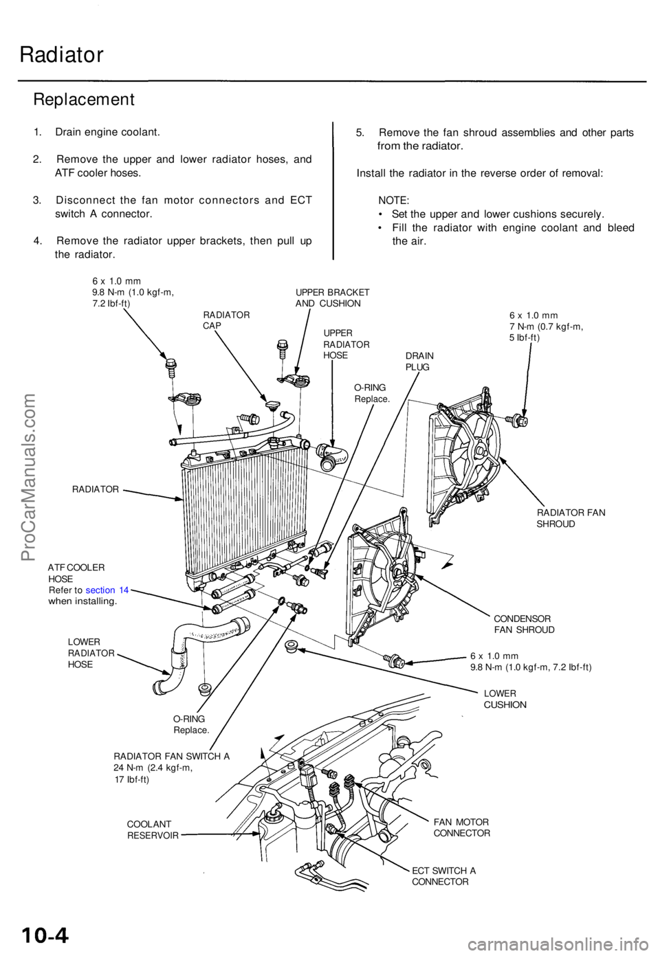
Replacemen t
1. Drai n engin e coolant .
2 . Remov e th e uppe r an d lowe r radiato r hoses , an d
AT F coole r hoses .
3 . Disconnec t th e fa n moto r connector s an d EC T
switc h A connector .
4 . Remov e th e radiato r uppe r brackets , the n pul l u p
th e radiator . 5
. Remov e th e fa n shrou d assemblie s an d othe r part s
from th e radiator .
Install th e radiato r i n th e revers e orde r o f removal :
NOTE:
• Se t th e uppe r an d lowe r cushion s securely .
• Fil l th e radiato r wit h engin e coolan t an d blee d
the air .
6 x 1. 0 m m9.8 N- m (1. 0 kgf-m ,
7. 2 Ibf-ft )UPPE R BRACKE TAND CUSHIO N
RADIATO R
ATF COOLE R
HOS E
Refe r t o sectio n 1 4
whe n installing .
LOWERRADIATO RHOSE
RADIATO R FA N SWITC H A
2 4 N- m (2. 4 kgf-m ,
1 7 Ibf-ft )
COOLAN T
RESERVOI R
6 x 1. 0 m m7 N- m (0. 7 kgf-m ,
5 Ibf-ft )
RADIATO R FA N
SHROU D
CONDENSO R
FA N SHROU D
6 x 1. 0 m m9.8 N- m (1. 0 kgf-m , 7. 2 Ibf-ft )
LOWE RCUSHIO N
FAN MOTO R
CONNECTO R
EC T SWITC H A
CONNECTO R
O-RIN
G
Replace .
DRAIN
PLU G
O-RIN G
Replace .
UPPERRADIATO RHOSE
RADIATO RCAP
ProCarManuals.com
Page 826 of 1771
Radiator
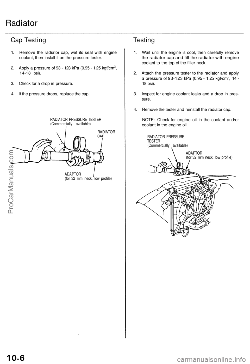
Cap Testin g
1. Remov e th e radiato r cap , we t it s sea l wit h engin e
coolant , the n instal l i t o n th e pressur e tester .
2 . Appl y a pressur e o f 9 3 - 12 3 kP a (0.9 5 - 1.2 5 kgf/cm
2,
14-1 8 psi) .
3. Chec k fo r a dro p in pressure .
4 . I f th e pressur e drops , replac e th e cap .
RADIATO R PRESSUR E TESTE R
(Commerciall y available )
RADIATO R
CAP
ADAPTO R
(fo r 3 2 m m neck , lo w profile )
Testing
1. Wai t unti l th e engin e i s cool , the n carefull y remov e
the radiato r ca p an d fil l th e radiato r wit h engin e
coolan t t o th e to p o f th e fille r neck .
2 . Attac h th e pressur e teste r t o th e radiato r an d appl y
a pressur e o f 93-12 3 kP a (0.9 5 - 1.2 5 kgf/cm
2, 1 4 -
18 psi) .
3. Inspec t fo r engin e coolan t leak s an d a dro p i n pres -
sure.
4. Remov e th e teste r an d reinstal l th e radiato r cap .
NOTE : Chec k fo r engin e oi l i n th e coolan t and/o r
coolan t i n th e engine oil.
RADIATO R PRESSUR ETESTER(Commerciall y available )
ADAPTO R
(for 3 2 m m neck , lo w profile )
ProCarManuals.com
Page 828 of 1771
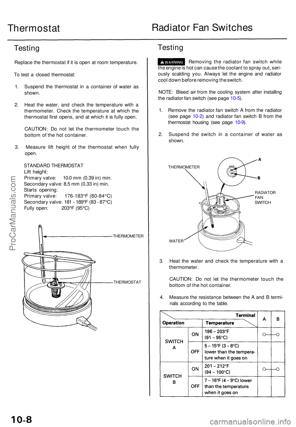
Thermostat Radiato
r Fa n Switche s
Testing
Replac e th e thermosta t i f i t i s ope n a t roo m temperature .
T o tes t a close d thermostat :
1 . Suspen d th e thermosta t i n a containe r o f wate r a s
shown .
2 . Hea t th e water , an d chec k th e temperatur e wit h a
thermometer . Chec k th e temperatur e a t whic h th e
thermosta t firs t opens , an d a t whic h i t i s full y open .
CAUTION : D o no t le t th e thermomete r touc h th e
botto m of th e ho t container .
3 . Measur e lif t heigh t of the thermosta t whe n full y
open .
STANDAR D THERMOSTA T
Lift height :
Primar y valve : 10. 0 m m (0.3 9 in ) min .
Secondar y valve : 8. 5 m m (0.3 3 in ) min .
Start s opening :
Primar y valve : 176-183° F (80-84°C )
Secondar y valve : 18 1 - 189° F (8 3 - 87°C )
Full y open : 203° F (95°C )
THERMOMETE R
THERMOSTA T
Testing
Removin g th e radiato r fa n switc h whil e
th e engin e is ho t ca n caus e th e coolan t t o spra y out , seri -
ousl y scaldin g you . Alway s le t th e engin e an d radiato r
coo l dow n befor e removin g th e switch .
NOTE : Blee d ai r fro m th e coolin g syste m afte r installin g
th e radiato r fa n switc h (se e pag e 10-5 ).
1 . Remov e th e radiato r fa n switc h A fro m th e radiato r
(se e pag e 10-2 ) an d radiato r fa n switc h B fro m th e
thermosta t housin g (se e pag e 10-9 ).
2 . Suspen d th e switc h i n a containe r of wate r a s
shown .
THERMOMETE R
RADIATORFANSWITC H
WATER
3. Hea t th e wate r an d chec k th e temperatur e wit h a
thermometer .
CAUTION : D o no t le t th e thermomete r touc h th e
botto m of th e ho t container .
4 . Measur e th e resistanc e betwee n th e A an d B termi -
nal s accordin g t o th e table .
ProCarManuals.com
Page 877 of 1771
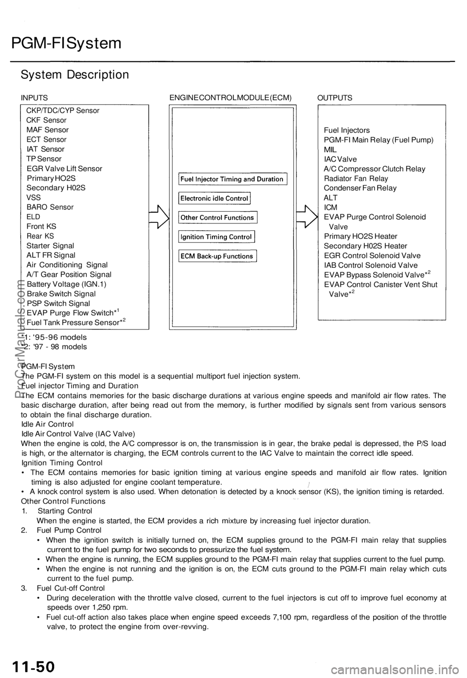
PGM-FI System
System Description
INPUTS
ENGINE CONTROL MODULE (ECM)
OUTPUTS
Fuel Injectors
PGM-FI Main Relay (Fuel Pump)
MIL
IAC Valve
A/C Compressor Clutch Relay
Radiator Fan Relay
Condenser Fan Relay
ALT
ICM
EVAP Purge Control Solenoid
Valve
Primary HO2S Heater
Secondary H02S Heater
EGR Control Solenoid Valve
IAB Control Solenoid Valve
EVAP Bypass Solenoid Valve*2
EVAP Control Canister Vent Shut
Valve*2
*1: '95-96 models
*2: '97 - 98 models
PGM-FI System
The PGM-FI system on this model is a sequential multiport fuel injection system.
Fuel injector Timing and Duration
The ECM contains memories for the basic discharge durations at various engine speeds and manifold air flow rates. The
basic discharge duration, after being read out from the memory, is further modified by signals sent from various sensors
to obtain the final discharge duration.
Idle Air Control
Idle Air Control Valve (IAC Valve)
When the engine is cold, the A/C compressor is on, the transmission is in gear, the brake pedal is depressed, the P/S load
is high, or the alternator is charging, the ECM controls current to the IAC Valve to maintain the correct idle speed.
Ignition Timing Control
• The ECM contains memories for basic ignition timing at various engine speeds and manifold air flow rates. Ignition
timing is also adjusted for engine coolant temperature.
• A knock control system is also used. When detonation is detected by a knock sensor (KS), the ignition timing is retarded.
Other Control Functions
1. Starting Control
When the engine is started, the ECM provides a rich mixture by increasing fuel injector duration.
2. Fuel Pump Control
• When the ignition switch is initially turned on, the ECM supplies ground to the PGM-FI main relay that supplies
current to the fuel pump for two seconds to pressurize the fuel system.
• When the engine is running, the ECM supplies ground to the PGM-FI main relay that supplies current to the fuel pump.
• When the engine is not running and the ignition is on, the ECM cuts ground to the PGM-FI main relay which cuts
current to the fuel pump.
3. Fuel Cut-off Control
• During deceleration with the throttle valve closed, current to the fuel injectors is cut off to improve fuel economy at
speeds over 1,250 rpm.
• Fuel cut-off action also takes place when engine speed exceeds 7,100 rpm, regardless of the position of the throttle
valve, to protect the engine from over-revving.
CKP/TDC/CYP Sensor
CKF Sensor
MAF Sensor
ECT Sensor
IAT Sensor
TP Sensor
EGR Valve Lift Sensor
Primary HO2S
Secondary H02S
VSS
BARO Sensor
ELD
Front KS
Rear KS
Starter Signal
ALT FR Signal
Air Conditioning Signal
A/T Gear Position Signal
Battery Voltage (IGN.1)
Brake Switch Signal
PSP Switch Signal
EVAP Purge Flow Switch*1
Fuel Tank Pressure Sensor*2ProCarManuals.com
Page 919 of 1771
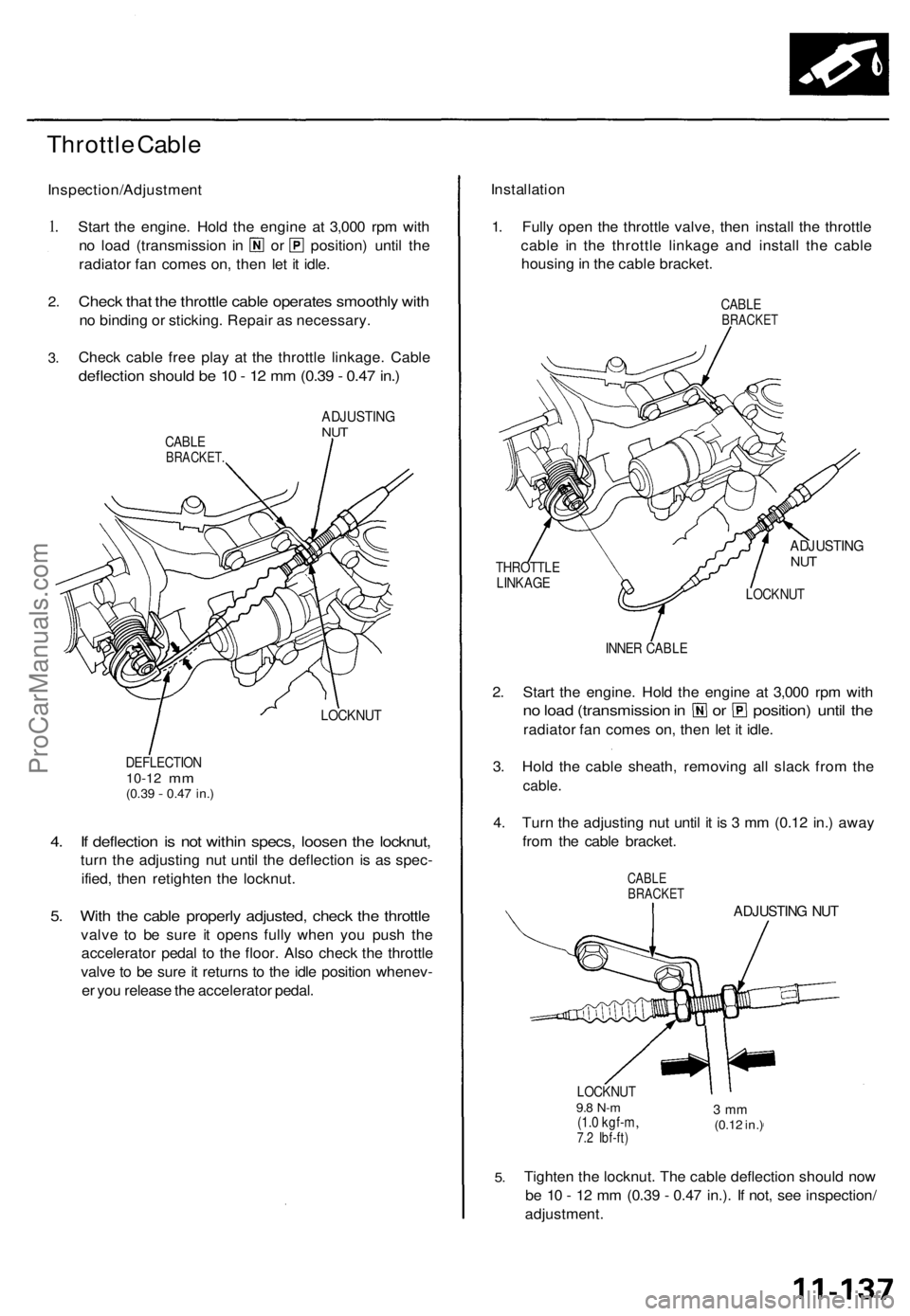
Throttle Cable
Inspection/Adjustment
1.
2.
3.
Start the engine. Hold the engine at 3,000 rpm with
no load (transmission in or position) until the
radiator fan comes on, then let it idle.
Check that the throttle cable operates smoothly with
no binding or sticking. Repair as necessary.
Check cable free play at the throttle linkage. Cable
deflection should be 10 - 12 mm (0.39 - 0.47 in.)
CABLE
BRACKET.
ADJUSTING
NUT
LOCKNUT
DEFLECTION
10-12
mm
(0.39
-
0.47 in.)
4. If deflection is not within specs, loosen the locknut,
turn the adjusting nut until the deflection is as spec-
ified, then retighten the locknut.
5. With the cable properly adjusted, check the throttle
valve to be sure it opens fully when you push the
accelerator pedal to the floor. Also check the throttle
valve to be sure it returns to the idle position whenev-
er you release the accelerator pedal.
Installation
1. Fully open the throttle valve, then install the throttle
cable in the throttle linkage and install the cable
housing in the cable bracket.
CABLE
BRACKET
THROTTLE
LINKAGE
ADJUSTING
NUT
LOCKNUT
INNER CABLE
2. Start the engine. Hold the engine at 3,000 rpm with
no load (transmission in or position) until the
radiator fan comes on, then let it idle.
3. Hold the cable sheath, removing all slack from the
cable.
4. Turn the adjusting nut until it is 3 mm (0.12 in.) away
from the cable bracket.
CABLE
BRACKET
ADJUSTING NUT
LOCKNUT
9.8 N-m
(1.0 kgf-m,
7.2 Ibf-ft)
3 mm
(0.12 in.)
5.
Tighten the locknut. The cable deflection should now
be 10 - 12 mm (0.39 - 0.47 in.). If not, see inspection/
adjustment.ProCarManuals.com
Page 1087 of 1771
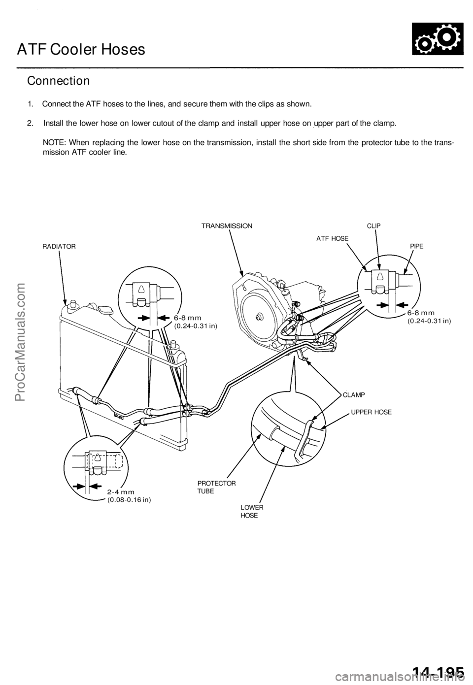
ATF Cooler Hoses
Connection
1. Connect the ATF hoses to the lines, and secure them with the clips as shown.
2. Install the lower hose on lower cutout of the clamp and install upper hose on upper part of the clamp.
NOTE: When replacing the lower hose on the transmission, install the short side from the protector tube to the trans-
mission ATF cooler line.
TRANSMISSION
CLIP
RADIATOR
PIPE
6-8 mm
(0.24-0.31 in)
CLAMP
UPPER HOSE
LOWER
HOSE
PROTECTOR
TUBE
2-4 mm
(0.08-0.16 in)
ATF HOSE
6-8 mm
(0.24-0.31 in)ProCarManuals.com