Page 1494 of 1771

Troubleshooting
Symptom Char t
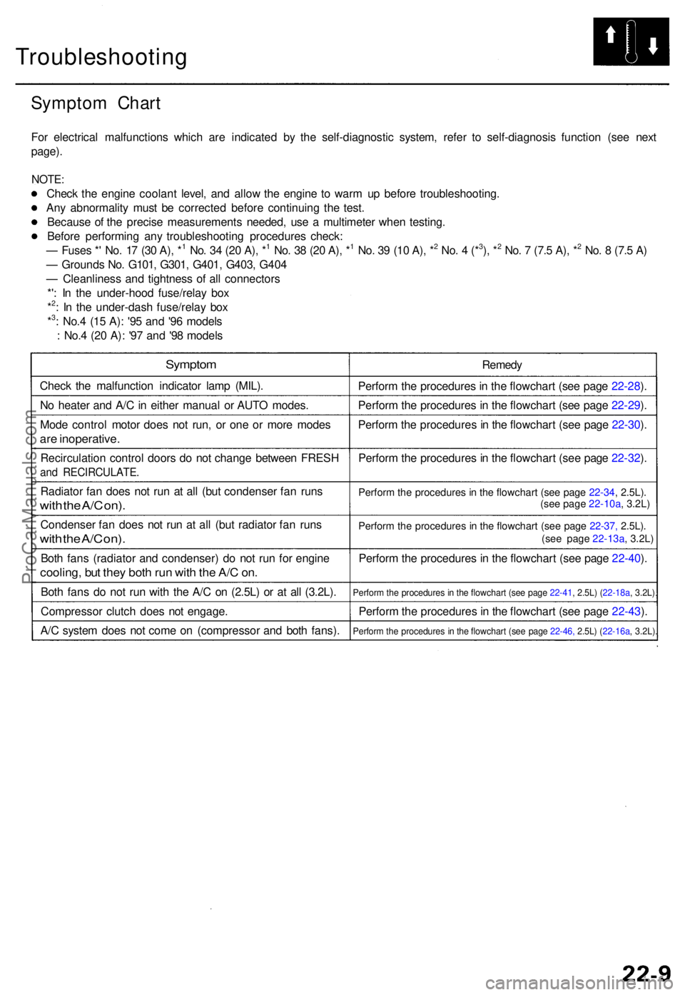
For electrica l malfunction s whic h ar e indicate d b y th e self-diagnosti c system , refe r t o self-diagnosi s functio n (se e nex t
page) .
NOTE :
Check th e engin e coolan t level , an d allo w th e engin e t o war m u p befor e troubleshooting .
An y abnormalit y mus t b e correcte d befor e continuin g th e test .
Becaus e o f th e precis e measurement s needed , us e a multimete r whe n testing .
Befor e performin g an y troubleshootin g procedure s check :
— Fuse s * ' No . 1 7 (3 0 A) , *
1 No . 3 4 (2 0 A) , *1 No . 3 8 (2 0 A) , *1 No . 3 9 (1 0 A) , *2 No . 4 (*3), *2 No . 7 (7. 5 A) , *2 No . 8 (7. 5 A )
— Ground s No . G101 , G301 , G401 , G403 , G40 4
— Cleanlines s an d tightnes s o f al l connector s
*' : I n th e under-hoo d fuse/rela y bo x
*
2: I n th e under-das h fuse/rela y bo x
*3: No. 4 (1 5 A) : '9 5 an d '9 6 model s
: No. 4 (2 0 A) : '9 7 an d '9 8 model s
Sympto m
Check th e malfunctio n indicato r lam p (MIL) .
N o heate r an d A/ C in eithe r manual or AUT O modes .
Mod e contro l moto r doe s no t run , o r on e o r mor e mode s
are inoperative .
Recirculatio n contro l door s d o no t chang e betwee n FRES H
and RECIRCULATE .
Radiator fa n doe s no t ru n a t al l (bu t condense r fa n run s
with th e A/ C on) .
Condense r fa n doe s no t ru n a t al l (bu t radiato r fa n run s
with th e A/ C on) .
Both fan s (radiato r an d condenser ) d o no t ru n fo r engin e
cooling , bu t the y bot h ru n wit h th e A/ C on .
Bot h fan s d o no t ru n wit h th e A/ C on (2.5L) or at all (3.2L) .
Compresso r clutc h doe s no t engage .
A/ C syste m doe s no t com e o n (compresso r an d bot h fans) . Remed
y
Perfor m th e procedure s in th e flowchar t (se e pag e 22-28 ).
Perfor m th e procedure s in th e flowchar t (se e pag e 22-29 ).
Perfor m th e procedure s in th e flowchar t (se e pag e 22-30 ).
Perfor m th e procedure s in th e flowchar t (se e pag e 22-32 ).
Perfor m th e procedure s in th e flowchar t (se e pag e 22-34 , 2.5L) .
Perfor m th e procedure s i n th e flowchar t (se e pag e 22-37, 2.5L).
Perfor m th e procedure s in th e flowchar t (se e pag e 22-40 ).
Perfor m th e procedure s in th e flowchar t (se e pag e 22-41 , 2.5L) ( 22-18a, 3.2L).
Perfor m th e procedure s in th e flowchar t (se e pag e 22-43 ).
Perfor m th e procedure s i n th e flowchar t (se e pag e 22-46, 2.5L) (22-16a , 3.2L).
(see page 22-10a, 3.2L)
(see page 22-13a , 3.2L)
ProCarManuals.com
Page 1497 of 1771

Troubleshooting
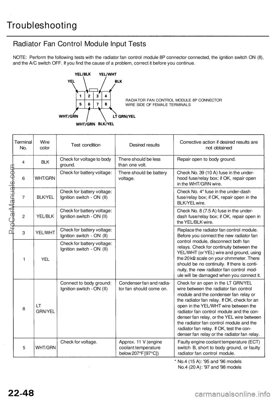
Radiator Fan Control Module Input Tests
NOTE: Perform the following tests with the radiator fan control module 8P connector connected, the ignition switch ON (II),
and the A/C switch OFF. If you find the cause of a problem, correct it before you continue.
RADIATOR FAN CONTROL MODULE 8P CONNECTOR
WIRE SIDE OF FEMALE TERMINALS
Terminal
No.
4
6
7
2
3
1
8
5
Wire
color
BLK
WHT/GRN
BLK/YEL
YEL/BLK
YEL/WHT
YEL
LT
GRN/YEL
WHT/GRN
Test condition
Check for voltage to body
ground.
Check for battery voltage:
Check for battery voltage:
Ignition switch - ON (II)
Check for battery voltage:
Ignition switch - ON (II)
Check for battery voltage:
Ignition switch - ON (II)
Check for battery voltage:
Ignition switch - ON (II)
Connect to body ground:
Ignition switch - ON (II)
Check for voltage.
Desired results
There should be less
than one volt.
There should be battery
voltage.
Condenser fan and radia-
tor fan should come on.
Approx. 11 V (engine
coolant temperature
below 207°F [97°C])
Corrective action if desired results are
not obtained
Repair open to body ground.
Check No. 39 (10 A) fuse in the under-
hood fuse/relay box; if OK, repair open
in the WHT/GRN wire.
Check No. 4* fuse in the under-dash
fuse/relay box; if OK, repair open in the
BLK/YEL wire.
Check No. 8 (7.5 A) fuse in the under-
dash fuse/relay box; if OK, repair open in
the YEL/BLK wire.
Replace the radiator fan control module.
Before you connect the new radiator fan
control module, disconnect both fan
relays. Check for continuity between the
YEL/WHT (or YEL) wire and ground, using
the 20 k scale on your ohmmeter. There
should be no continuity. If there is conti-
nuity, the new radiator fan control mod-
ule will be damaged when you connect it.
Check for an open in the LT GRN/YEL
wire between the radiator fan control
module and the condenser fan relay or
the radiator fan relay. If OK, check for an
open in the YEL/WHT wire between the
radiator fan control module and the con-
denser fan relay, or the YEL wire between
the radiator fan control module and the
radiator fan relay. If OK, test the con-
denser fan relay or the radiator fan relay.
Faulty engine coolant temperature (ECT)
switch B, short to body ground, or faulty
radiator fan control module.
* No.4 (15 A): '95 and '96 models
No.4 (20 A): '97 and '98 modelsProCarManuals.com
Page 1530 of 1771

Condenser
Replacemen t
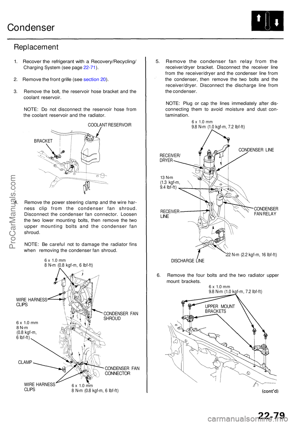
1. Recove r th e refrigeran t wit h a Recovery/Recycling /
Charging Syste m (se e pag e 22-71 ).
2 . Remov e th e fron t grill e (se e sectio n 20 ).
3 . Remov e th e bolt , th e reservoi r hos e bracke t an d th e
coolan t reservoir .
NOTE : D o no t disconnec t th e reservoi r hos e fro m
th e coolan t reservoi r an d th e radiator .
COOLAN T RESERVOI R
BRACKET
4. Remov e th e powe r steerin g clam p an d th e wir e har -
nes s cli p fro m th e condense r fa n shroud .
Disconnec t th e condense r fa n connector . Loose n
th e tw o lowe r mountin g bolts , the n remov e th e tw o
uppe r mountin g bolt s an d th e condense r fa n
shroud .
NOTE : B e carefu l no t t o damag e th e radiato r fin s
whe n removin g th e condense r fa n shroud .
6 x 1. 0 m m8 N- m (0. 8 kgf-m , 6 Ibf-ft )
WIR E HARNES S
CLIPS
6 x 1. 0 m m8 N- m(0.8 kgf-m ,
6 Ibf-ft )
CLAM P
WIR E HARNES S
CLIP S CONDENSE
R FA N
SHROU D
CONDENSE R FA N
CONNECTO R
6 x 1. 0 m m8 N- m (0. 8 kgf-m , 6 Ibf-ft )
5. Remov e th e condense r fa n rela y fro m th e
receiver/drye r bracket . Disconnec t th e receive r lin e
fro m th e receiver/drye r an d th e condense r lin e fro m
th e condenser , the n remov e th e tw o bolt s an d th e
receiver/dryer . Disconnec t th e discharg e lin e fro m
th e condenser .
NOTE : Plu g o r ca p th e line s immediatel y afte r dis -
connectin g the m to avoi d moistur e an d dus t con -
tamination .
6 x 1. 0 m m9.8 N- m (1. 0 kgf-m , 7. 2 Ibf-ft )
RECEIVER /DRYER
13 N- m(1.3 kgf-m ,
9. 4 Ibf-ft )
RECEIVE RLINE
CONDENSE R LIN E
CONDENSE R
FA N RELA Y
2 2 N- m (2. 2 kgf-m , 1 6 Ibf-ft )
DISCHARG E LIN E
6. Remov e th e fou r bolt s an d th e tw o radiato r uppe r
moun t brackets .
6 x 1. 0 m m9.8 N- m (1. 0 kgf-m , 7. 2 Ibf-ft )
UPPE R MOUN T
BRACKET S
ProCarManuals.com
Page 1540 of 1771
Relay and Control Unit Locations
Engine Compartment (cont'd)
INTERMITTENT WIPER
RELAY
Wire colors: BLU/YEL, GRN/YEL,
BLK, GRN/BLK and BLU/WHT
A/C COMPRESSOR CLUTCH RELAY
Wire colors: RED/BLU, RED,
YEL/BLK and WHT
CONDENSER FAN RELAY
Wire colors: LT GRN/YEL,
WHT/GRN, YEL/WHT and WHT
RADIATOR FAN RELAY
Wire colors: LT GRN/YEL,
WHT/BLU, YEL and WHTProCarManuals.com
Page 1543 of 1771
CLIMATE CONTROL UNIT
RADIATOR
FAN CONTROL
MODULE
ABS CONTROL UNIT
('95 -97 models)
KEYLESS DOOR LOCK CONTROL
UNIT ('98 model)
SECURITY CONTROL
UNIT
ABS CONTROL UNIT
('98 model)
MOONROOF OPEN RELAY
Wire colors: GRY, GRN/YEL,
GRN,
YEL and BLK
MOONROOF CLOSE RELAY
Wire colors: GRY/RED, GRN/RED,
GRN,
YEL and BLK
TRANSMISSION
CONTROL
MODULE (TCM)ProCarManuals.com
Page 1589 of 1771

Fan Control s
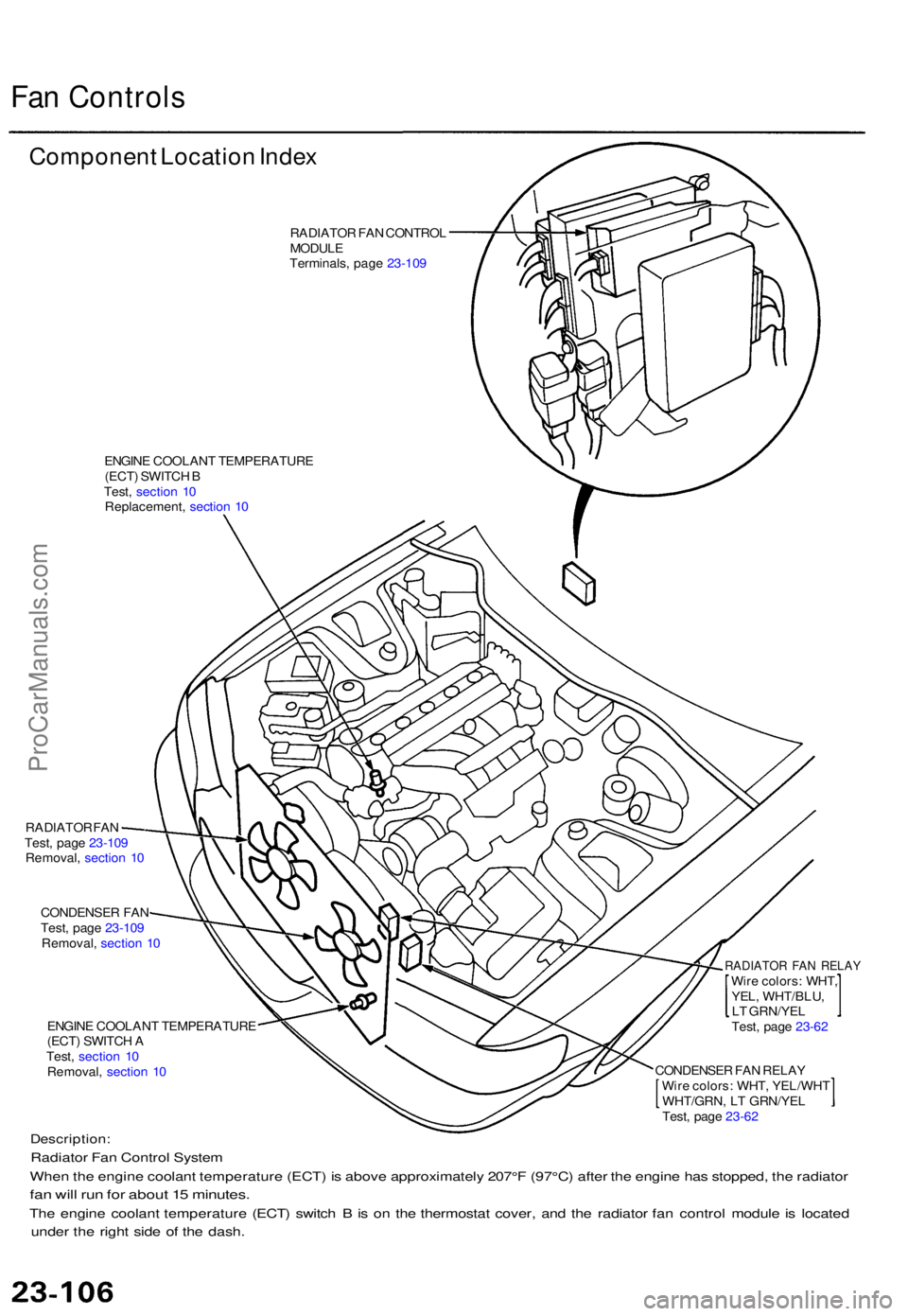
Componen t Locatio n Inde x
RADIATO R FA N CONTRO L
MODUL E
Terminals , pag e 23-10 9
ENGIN E COOLAN T TEMPERATUR E
(ECT ) SWITC H B
Test , sectio n 1 0
Replacement , sectio n 1 0
RADIATO R FA N
Test , pag e 23-10 9
Removal , sectio n 1 0
CONDENSE R FA N
Test , pag e 23-10 9
Removal , sectio n 1 0
ENGIN E COOLAN T TEMPERATUR E
(ECT ) SWITC H A
Test , sectio n 1 0
Removal , sectio n 1 0
RADIATO R FA N RELA YWire colors : WHT ,
YEL , WHT/BLU ,
L T GRN/YE L
Test , pag e 23-6 2
Description :
Radiator Fa n Contro l Syste m
Whe n th e engin e coolan t temperatur e (ECT ) i s abov e approximatel y 207° F (97°C ) afte r th e engin e ha s stopped , th e radiato r
fan wil l ru n fo r abou t 1 5 minutes .
The engin e coolan t temperatur e (ECT ) switc h B is o n th e thermosta t cover , an d th e radiato r fa n contro l modul e is locate d
unde r th e righ t sid e o f th e dash .
CONDENSE R FA N RELA Y
Wir e colors : WHT , YEL/WH T
WHT/GRN , L T GRN/YE L
Test , pag e 23-6 2
ProCarManuals.com
Page 1591 of 1771
Radiator Fa n Contro l Modul e
Terminal s
TERMINA L SID E O F
MAL E TERMINALS ,
Fan Moto r Tes t
RADIATO R FA NCONTRO LMODULE
NOTE: Se e sectio n 2 2 fo r th e inpu t test .
Termina lWire Connects to
1. Disconnec t th e 2 P connecto r fro m eac h fa n motor .
CONDENSE R FA N MOTO R RADIATO R FA N MOTO R
TERMINA L SID E O FMAL E TERMINAL S
2. Tes t th e moto r b y connectin g batter y powe r t o th e
No . 2 termina l an d groun d t o th e No . 1 terminal .
3 . I f th e moto r fail s t o ru n o r doe s no t ru n smoothly ,
replac e it .
ProCarManuals.com
Page:
< prev 1-8 9-16 17-24