Page 205 of 1771
Idle Control System
System Description
The idle speed of the engine is controlled by the Idle Air Control (IAC) Valve.
The valve changes the amount of air bypassing into the intake manifold in response to electric current controlled by the
PCM. When the IAC Valve is activated, the valve opens to maintain the proper idle speed.
ENGINE
COOLANT
IAC VALVE
INTAKE
MANIFOLD
PCM
From
PGM-FI
MAIN
RELAY
FAST
IDLE
THERMO
VALVE
IDLE
ADJUSTING
SCREW
VARIOUS
SENSORS
ENGINE
COOLANTProCarManuals.com
Page 239 of 1771
Intake Air System
System Description
The system supplies air for all engine needs. It consists of the intake air pipe, Air Cleaner (ACL), intake air duct, Throttle
Body (TB), Idle Air Control (IAC) Valve, fast idle thermo valve, and intake manifold.
A resonator in the intake air pipe provides additional silencing as air is drawn into the system.
IAB LOW
CONTROL
SOLENOID
VALVE
IAB HIGH
CONTROL SOLENOID VALVE
IAB LOW
CONTROL
DIAPHRAGM
VALVE
From PGM-FI
MAIN RELAY
From No. 4 ECU
(PCM)
(15 A)
FUSE
(in the under-dash
fuse/relay box)
VARIOUS
SENSORS
INTAKE
AIR
DUCT
FAST
IDLE
THERMO
VALVE
IDLE
ADJUSTING
SCREW
ENGINE
COOLANT
INTAKE
MANIFOLD
PCM
IAB
VACUUM
TANK
IAB
CHECK
VALVE
IAB HIGH
CONTROL
DIAPHRAGM
VALVEProCarManuals.com
Page 253 of 1771
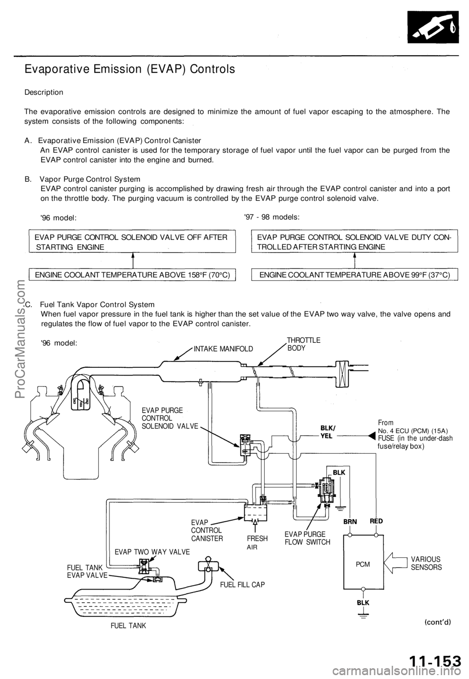
Evaporative Emission (EVAP) Controls
Description
The evaporative emission controls are designed to minimize the amount of fuel vapor escaping to the atmosphere. The
system consists of the following components:
A. Evaporative Emission (EVAP) Control Canister
An EVAP control canister is used for the temporary storage of fuel vapor until the fuel vapor can be purged from the
EVAP control canister into the engine and burned.
B. Vapor Purge Control System
EVAP control canister purging is accomplished by drawing fresh air through the EVAP control canister and into a port
on the throttle body. The purging vacuum is controlled by the EVAP purge control solenoid valve.
'96 model:
'97 - 98 models:
C. Fuel Tank Vapor Control System
When fuel vapor pressure in the fuel tank is higher than the set value of the EVAP two way valve, the valve opens and
regulates the flow of fuel vapor to the EVAP control canister.
'96 model:
INTAKE MANIFOLD
THROTTLE
BODY
EVAP PURGE
CONTROL
SOLENOID VALVE
FUEL TANK
EVAP VALVE
EVAP TWO WAY VALVE
From
No. 4 ECU
(PCM) (15A)
FUSE (in the under-dash
fuse/relay box)
EVAP
CONTROL
CANISTER FRESH
AIR
EVAP PURGE
FLOW SWITCH
FUEL FILL CAP
PCM
VARIOUS
SENSORS
FUEL TANK
ENGINE COOLANT TEMPERATURE ABOVE 158°F (70°C)
ENGINE COOLANT TEMPERATURE ABOVE 99°F (37°C)
EVAP PURGE CONTROL SOLENOID VALVE DUTY CON-
TROLLED AFTER STARTING ENGINE
EVAP PURGE CONTROL SOLENOID VALVE OFF AFTER
STARTING ENGINEProCarManuals.com
Page 275 of 1771
Grade Logic Control System
How it works:
The PCM compares actual driving conditions with driving conditions memorized in the PCM, based on the input from the
vehicle speed sensor, throttle position sensor, engine coolant temperature sensor, barometric pressure sensor, brake
switch signal and shift lever position signal, to control shifting while a vehicle is ascending or descending a slope, or
reducing speed.
(cont'd)ProCarManuals.com
Page 727 of 1771
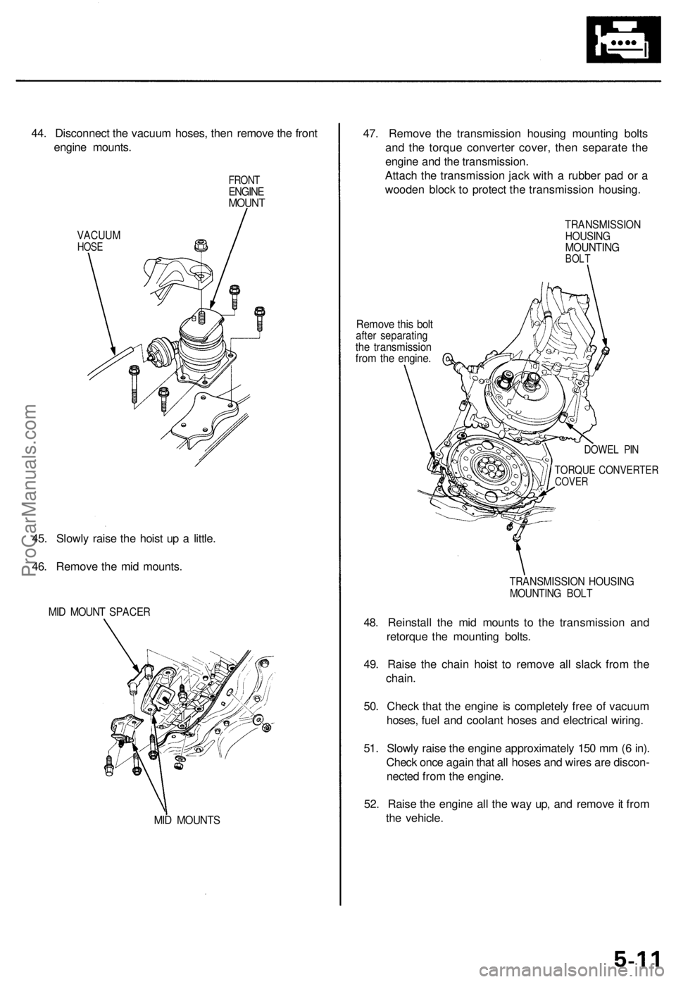
44. Disconnect the vacuum hoses, then remove the front
engine mounts.
VACUUM
HOSE
FRONT
ENGINE
MOUNT
45. Slowly raise the hoist up a little.
46. Remove the mid mounts.
MID MOUNT SPACER
MID MOUNTS
47. Remove the transmission housing mounting bolts
and the torque converter cover, then separate the
engine and the transmission.
Attach the transmission jack with a rubber pad or a
wooden block to protect the transmission housing.
Remove this bolt
after separating
the transmission
from the engine.
TRANSMISSION
HOUSING
MOUNTING
BOLT
DOWEL PIN
TORQUE CONVERTER
COVER
TRANSMISSION HOUSING
MOUNTING BOLT
48. Reinstall the mid mounts to the transmission and
retorque the mounting bolts.
49. Raise the chain hoist to remove all slack from the
chain.
50. Check that the engine is completely free of vacuum
hoses, fuel and coolant hoses and electrical wiring.
51. Slowly raise the engine approximately 150 mm (6 in).
Check once again that all hoses and wires are discon-
nected from the engine.
52. Raise the engine all the way up, and remove it from
the vehicle.ProCarManuals.com
Page 752 of 1771
Cylinder Head
Removal (cont'd)
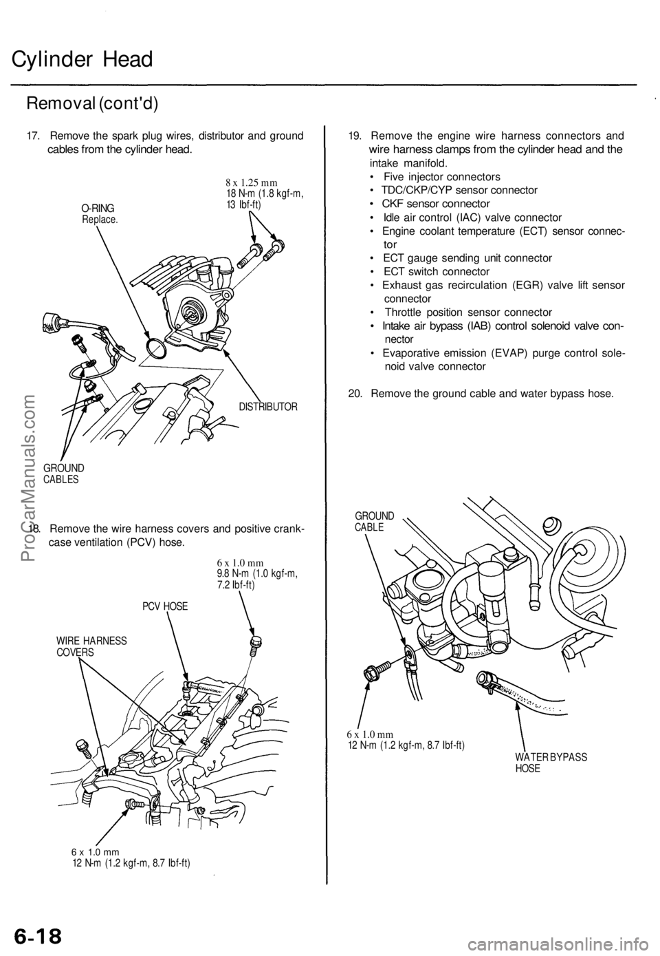
17. Remove the spark plug wires, distributor and ground
cables from the cylinder head.
O-RING
Replace.
8 x
1.25
mm
18 N-m (1.8 kgf-m,
13 Ibf-ft)
DISTRIBUTOR
GROUND
CABLES
18. Remove the wire harness covers and positive crank-
case ventilation (PCV) hose.
6 x 1.0 mm
9.8 N-m (1.0 kgf-m,
7.2 Ibf-ft)
PCV HOSE
WIRE HARNESS
COVERS
6 x 1.0 mm
12 N-m (1.2 kgf-m, 8.7 Ibf-ft)
19. Remove the engine wire harness connectors and
wire harness clamps from the cylinder head and the
intake manifold.
• Five injector connectors
• TDC/CKP/CYP sensor connector
• CKF sensor connector
• Idle air control (IAC) valve connector
• Engine coolant temperature (ECT) sensor connec-
tor
• ECT gauge sending unit connector
• ECT switch connector
• Exhaust gas recirculation (EGR) valve lift sensor
connector
• Throttle position sensor connector
• Intake air bypass (IAB) control solenoid valve con-
nector
• Evaporative emission (EVAP) purge control sole-
noid valve connector
20. Remove the ground cable and water bypass hose.
GROUND
CABLE
6 x 1.0 mm
12 N-m (1.2 kgf-m, 8.7 Ibf-ft)
WATER BYPASS
HOSEProCarManuals.com
Page 822 of 1771
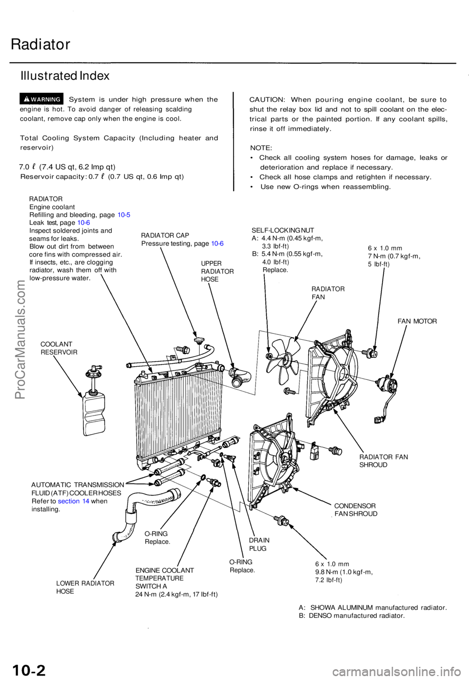
Radiator
Illustrate d Inde x
Syste m is unde r hig h pressur e whe n th e
engin e i s hot . T o avoi d dange r o f releasin g scaldin g
coolant , remov e ca p onl y whe n th e engin e i s cool .
Total Coolin g Syste m Capacit y (Includin g heate r an d
reservoir )
7.0 (7. 4 US qt , 6. 2 Im p qt )
Reservoi r capacity : 0. 7 (0. 7 U S qt , 0. 6 Im p qt )
RADIATO REngine coolan t
Refillin g an d bleeding , pag e 10- 5
Lea k test , pag e 10- 6
Inspec t soldere d joint s an d
seam s fo r leaks .
Blo w ou t dir t fro m betwee n
cor e fin s wit h compresse d air .
I f insects , etc. , ar e cloggin g
radiator , was h the m of f wit h
low-pressur e water .
CAUTION : Whe n pourin g engin e coolant , b e sur e t o
shu t th e rela y bo x li d an d no t t o spil l coolan t o n th e elec -
trica l part s o r th e painte d portion . I f an y coolan t spills ,
rins e i t of f immediately .
NOTE:
• Chec k al l coolin g syste m hose s fo r damage , leak s o r
deterioratio n an d replac e i f necessary .
• Chec k al l hos e clamp s an d retighte n i f necessary .
• Us e ne w O-ring s whe n reassembling .
RADIATOR CA PPressur e testing , pag e 10- 6
SELF-LOCKIN G NU TA: 4. 4 N- m (0.4 5 kgf-m ,3.3 Ibf-ft )B: 5. 4 N- m (0.5 5 kgf-m ,4.0 Ibf-ft )Replace .
6 x 1. 0 m m7 N- m (0. 7 kgf-m ,5 Ibf-ft )
COOLAN TRESERVOI R
FAN MOTO R
RADIATO R FA NSHROU D
AUTOMATI C TRANSMISSIO N
FLUI D (ATF ) COOLE R HOSE S
Refe r t o sectio n 1 4 whe n
installing .
CONDENSO RFAN SHROU D
LOWER RADIATO RHOSE
ENGIN E COOLAN TTEMPERATUR ESWITCH A
2 4 N- m (2. 4 kgf-m , 1 7 Ibf-ft )
O-RIN GReplace .6 x 1. 0 m m9.8 N- m (1. 0 kgf-m ,7.2 Ibf-ft )
A: SHOW A ALUMINU M manufacture d radiator .
B : DENS O manufacture d radiator .
O-RINGReplace .DRAINPLUG
UPPE RRADIATO RHOSE
RADIATO RFAN
ProCarManuals.com
Page 825 of 1771
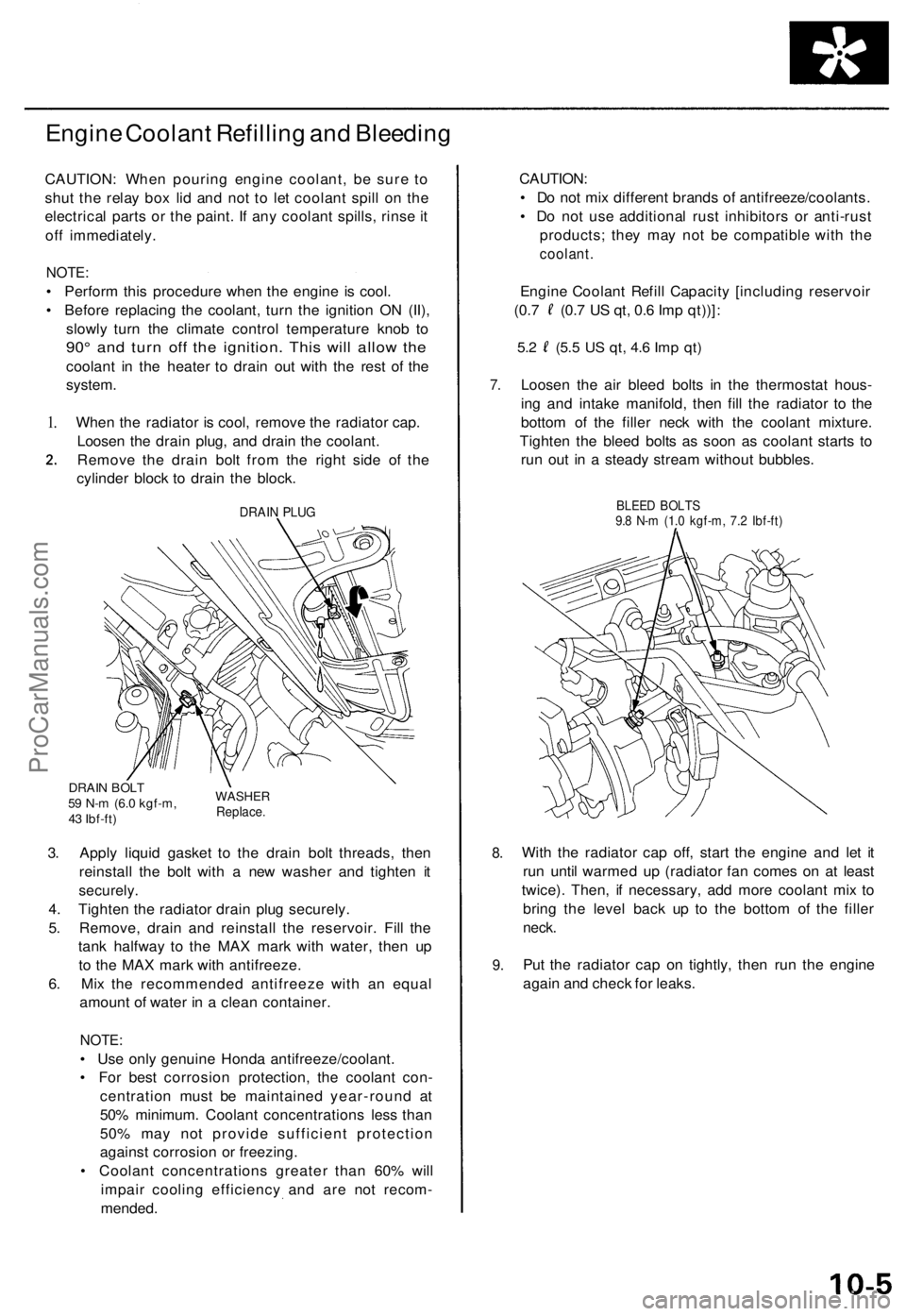
Engine Coolan t Refillin g an d Bleedin g
CAUTION : Whe n pourin g engin e coolant , b e sur e t o
shu t th e rela y bo x li d an d no t t o le t coolan t spil l o n th e
electrica l part s o r th e paint . I f an y coolan t spills , rins e it
of f immediately .
NOTE:
• Perfor m thi s procedur e whe n th e engin e i s cool .
• Befor e replacin g th e coolant , tur n th e ignitio n O N (II) ,
slowl y tur n th e climat e contro l temperatur e kno b t o
90 ° an d tur n of f th e ignition . Thi s wil l allo w th e
coolan t i n th e heate r t o drai n ou t wit h th e res t o f th e
system .
1.Whe n th e radiato r i s cool , remov e th e radiato r cap .
Loose n th e drai n plug , an d drai n th e coolant .
Remov e th e drai n bol t fro m th e righ t sid e o f th e
cylinde r bloc k t o drai n th e block .
DRAIN PLU G
DRAI N BOL T59 N- m (6. 0 kgf-m ,
4 3 Ibf-ft )WASHE RReplace.
3. Appl y liqui d gaske t t o th e drai n bol t threads , the n
reinstal l th e bol t wit h a ne w washe r an d tighte n i t
securely .
4. Tighte n th e radiato r drai n plu g securely .
5 . Remove , drai n an d reinstal l th e reservoir . Fil l th e
tan k halfwa y t o th e MA X mar k wit h water , the n u p
t o th e MA X mar k wit h antifreeze .
6 . Mi x th e recommende d antifreez e wit h a n equa l
amoun t o f wate r i n a clea n container .
NOTE:
• Us e onl y genuin e Hond a antifreeze/coolant .
• Fo r bes t corrosio n protection , th e coolan t con -
centratio n mus t b e maintaine d year-roun d a t
50 % minimum . Coolan t concentration s les s tha n
50 % ma y no t provid e sufficien t protectio n
agains t corrosio n o r freezing .
• Coolan t concentration s greate r tha n 60 % wil l
impai r coolin g efficienc y an d ar e no t recom -
mended .
7.
8.
9 .
CAUTION :
• D o no t mi x differen t brand s o f antifreeze/coolants .
• D o no t us e additiona l rus t inhibitor s o r anti-rus t
products ; the y ma y no t b e compatibl e wit h th e
coolant.
Engin e Coolan t Refil l Capacit y [includin g reservoi r
(0.7 (0. 7 U S qt , 0. 6 Im p qt))] :
5.2 (5. 5 US qt , 4. 6 Im p qt )
Loose n th e ai r blee d bolt s i n th e thermosta t hous -
in g an d intak e manifold , the n fil l th e radiato r t o th e
botto m o f th e fille r nec k wit h th e coolan t mixture .
Tighte n th e blee d bolt s a s soo n a s coolan t start s t o
ru n ou t i n a stead y strea m withou t bubbles .
BLEED BOLT S9.8 N- m (1. 0 kgf-m , 7. 2 Ibf-ft )
With th e radiato r ca p off , star t th e engin e an d le t i t
ru n unti l warme d u p (radiato r fa n come s o n a t leas t
twice) . Then , i f necessary , ad d mor e coolan t mi x t o
brin g th e leve l bac k u p t o th e botto m o f th e fille r
neck.
Put th e radiato r ca p o n tightly , the n ru n th e engin e
agai n an d chec k fo r leaks .
ProCarManuals.com