1995 ACURA TL engine coolant
[x] Cancel search: engine coolantPage 826 of 1771
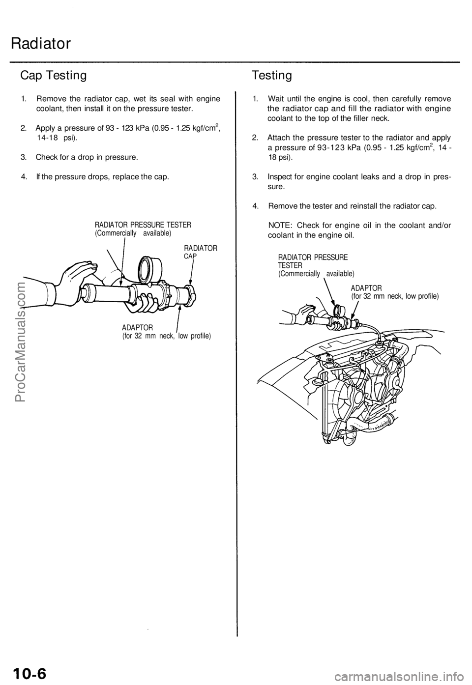
Radiator
Cap Testin g
1. Remov e th e radiato r cap , we t it s sea l wit h engin e
coolant , the n instal l i t o n th e pressur e tester .
2 . Appl y a pressur e o f 9 3 - 12 3 kP a (0.9 5 - 1.2 5 kgf/cm
2,
14-1 8 psi) .
3. Chec k fo r a dro p in pressure .
4 . I f th e pressur e drops , replac e th e cap .
RADIATO R PRESSUR E TESTE R
(Commerciall y available )
RADIATO R
CAP
ADAPTO R
(fo r 3 2 m m neck , lo w profile )
Testing
1. Wai t unti l th e engin e i s cool , the n carefull y remov e
the radiato r ca p an d fil l th e radiato r wit h engin e
coolan t t o th e to p o f th e fille r neck .
2 . Attac h th e pressur e teste r t o th e radiato r an d appl y
a pressur e o f 93-12 3 kP a (0.9 5 - 1.2 5 kgf/cm
2, 1 4 -
18 psi) .
3. Inspec t fo r engin e coolan t leak s an d a dro p i n pres -
sure.
4. Remov e th e teste r an d reinstal l th e radiato r cap .
NOTE : Chec k fo r engin e oi l i n th e coolan t and/o r
coolan t i n th e engine oil.
RADIATO R PRESSUR ETESTER(Commerciall y available )
ADAPTO R
(for 3 2 m m neck , lo w profile )
ProCarManuals.com
Page 839 of 1771
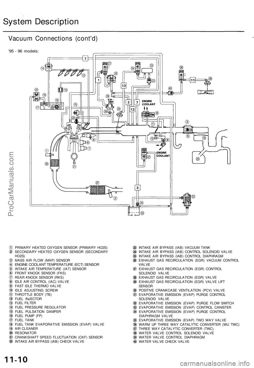
System Description
Vacuum Connections (cont'd)
'95 - 96 models:
PRIMARY HEATED OXYGEN SENSOR (PRIMARY HO2S)
SECONDARY HEATED OXYGEN SENSOR (SECONDARY
HO2S)
MASS AIR FLOW (MAP) SENSOR
ENGINE COOLANT TEMPERATURE (ECT) SENSOR
INTAKE AIR TEMPERATURE (IAT) SENSOR
FRONT KNOCK SENSOR (FKS)
REAR KNOCK SENSOR (RKS)
IDLE AIR CONTROL (IAC) VALVE
FAST IDLE THERMO VALVE
IDLE ADJUSTING SCREW
THROTTLE BODY (TB)
FUEL INJECTOR
FUEL FILTER
FUEL PRESSURE REGULATOR
FUEL PULSATION DAMPER
FUEL PUMP (FP)
FUEL TANK
FUEL TANK EVAPORATIVE EMISSION (EVAP) VALVE
AIR CLEANER
RESONATOR
CRANKSHAFT SPEED FLUCTUATION (CKF) SENSOR
INTAKE AIR BYPASS (IAB) CHECK VALVE
INTAKE AIR BYPASS (IAB) VACUUM TANK
INTAKE AIR BYPASS (IAB) CONTROL SOLENOID VALVE
INTAKE AIR BYPASS (IAB) CONTROL DIAPHRAGM
EXHAUST GAS RECIRCULATION (EGR) VACUUM CONTROL
VALVE
EXHAUST GAS RECIRCULATION (EGR) CONTROL
SOLENOID VALVE
EXHAUST GAS RECIRCULATION (EGR) VALVE
EXHAUST GAS RECIRCULATION (EGR) VALVE LIFT
SENSOR
POSITIVE CRANKCASE VENTILATION (PCV) VALVE
EVAPORATIVE EMISSION (EVAP) PURGE CONTROL
SOLENOID VALVE
EVAPORATIVE EMISSION (EVAP) PURGE FLOW SWITCH
EVAPORATIVE EMISSION (EVAP) CONTROL CANISTER
EVAPORATIVE EMISSION (EVAP) PURGE CONTROL
DIAPHRAGM VALVE
EVAPORATIVE EMISSION (EVAP) TWO WAY VALVE
WARM UP THREE WAY CATALYTIC CONVERTER (WU TWC)
THREE WAY CATALYTIC CONVERTER (TWC)
WATER VALVE CONTROL SOLENOID VALVE
WATER VALVE CONTROL DIAPHRAGM
WATER VALVE CHECK VALVEProCarManuals.com
Page 840 of 1771
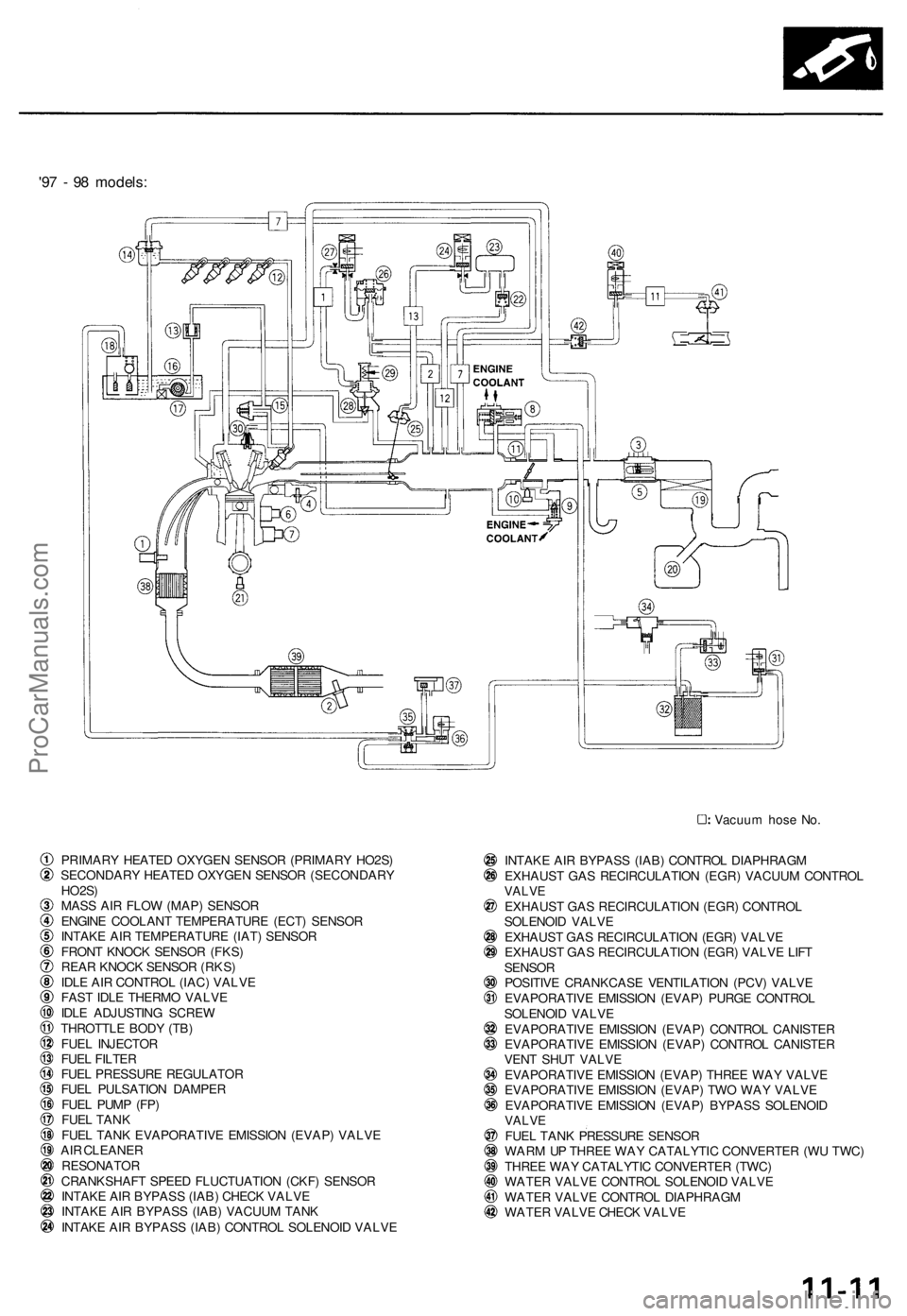
'97 - 98 models:
Vacuum hose No.
PRIMARY HEATED OXYGEN SENSOR (PRIMARY HO2S)
SECONDARY HEATED OXYGEN SENSOR (SECONDARY
HO2S)
MASS AIR FLOW (MAP) SENSOR
ENGINE COOLANT TEMPERATURE (ECT) SENSOR
INTAKE AIR TEMPERATURE (IAT) SENSOR
FRONT KNOCK SENSOR (FKS)
REAR KNOCK SENSOR (RKS)
IDLE AIR CONTROL (IAC) VALVE
FAST IDLE THERMO VALVE
IDLE ADJUSTING SCREW
THROTTLE BODY (TB)
FUEL INJECTOR
FUEL FILTER
FUEL PRESSURE REGULATOR
FUEL PULSATION DAMPER
FUEL PUMP (FP)
FUEL TANK
FUEL TANK EVAPORATIVE EMISSION (EVAP) VALVE
AIR CLEANER
RESONATOR
CRANKSHAFT SPEED FLUCTUATION (CKF) SENSOR
INTAKE AIR BYPASS (IAB) CHECK VALVE
INTAKE AIR BYPASS (IAB) VACUUM TANK
INTAKE AIR BYPASS (IAB) CONTROL SOLENOID VALVE
INTAKE AIR BYPASS (IAB) CONTROL DIAPHRAGM
EXHAUST GAS RECIRCULATION (EGR) VACUUM CONTROL
VALVE
EXHAUST GAS RECIRCULATION (EGR) CONTROL
SOLENOID VALVE
EXHAUST GAS RECIRCULATION (EGR) VALVE
EXHAUST GAS RECIRCULATION (EGR) VALVE LIFT
SENSOR
POSITIVE CRANKCASE VENTILATION (PCV) VALVE
EVAPORATIVE EMISSION (EVAP) PURGE CONTROL
SOLENOID VALVE
EVAPORATIVE EMISSION (EVAP) CONTROL CANISTER
EVAPORATIVE EMISSION (EVAP) CONTROL CANISTER
VENT SHUT VALVE
EVAPORATIVE EMISSION (EVAP) THREE WAY VALVE
EVAPORATIVE EMISSION (EVAP) TWO WAY VALVE
EVAPORATIVE EMISSION (EVAP) BYPASS SOLENOID
VALVE
FUEL TANK PRESSURE SENSOR
WARM UP THREE WAY CATALYTIC CONVERTER (WU TWC)
THREE WAY CATALYTIC CONVERTER (TWC)
WATER VALVE CONTROL SOLENOID VALVE
WATER VALVE CONTROL DIAPHRAGM
WATER VALVE CHECK VALVEProCarManuals.com
Page 867 of 1771
Troubleshooting
Troubleshooting Procedures (cont'd)
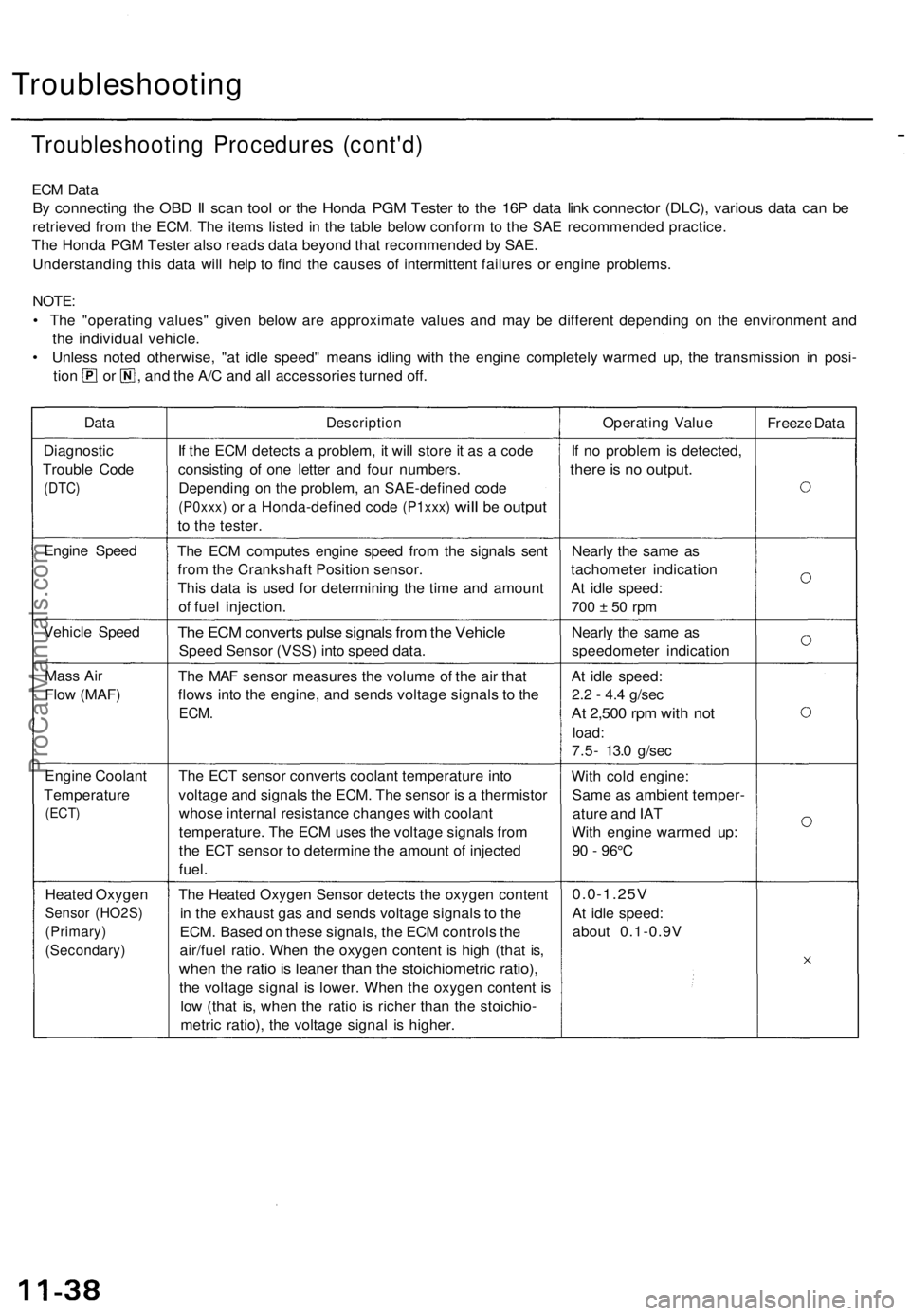
ECM Data
By connecting the OBD II scan tool or the Honda PGM Tester to the 16P data link connector (DLC), various data can be
retrieved from the ECM. The items listed in the table below conform to the SAE recommended practice.
The Honda PGM Tester also reads data beyond that recommended by SAE.
Understanding this data will help to find the causes of intermittent failures or engine problems.
NOTE:
• The "operating values" given below are approximate values and may be different depending on the environment and
the individual vehicle.
• Unless noted otherwise, "at idle speed" means idling with the engine completely warmed up, the transmission in posi-
tion or , and the A/C and all accessories turned off.
Data
Description
Operating Value
Freeze Data
Diagnostic
Trouble Code
(DTC)
If the ECM detects a problem, it will store it as a code
consisting of one letter and four numbers.
Depending on the problem, an SAE-defined code
(P0xxx)
or a
Honda-defined code
(P1xxx)
will
be
output
to the tester.
If no problem is detected,
there is no output.
Engine Speed
The ECM computes engine speed from the signals sent
from the Crankshaft Position sensor.
This data is used for determining the time and amount
of fuel injection.
Nearly the same as
tachometer indication
At idle speed:
700 ± 50 rpm
Vehicle Speed
The ECM converts pulse signals from the Vehicle
Speed Sensor (VSS) into speed data.
Nearly the same as
speedometer indication
Mass Air
Flow (MAF)
The MAF sensor measures the volume of the air that
flows into the engine, and sends voltage signals to the
ECM.
At idle speed:
2.2 - 4.4 g/sec
At 2,500 rpm with not
load:
7.5- 13.0 g/sec
Engine Coolant
Temperature
(ECT)
The ECT sensor converts coolant temperature into
voltage and signals the ECM. The sensor is a thermistor
whose internal resistance changes with coolant
temperature. The ECM uses the voltage signals from
the ECT sensor to determine the amount of injected
fuel.
With cold engine:
Same as ambient temper-
ature and IAT
With engine warmed up:
90 - 96°C
Heated Oxygen
Sensor (HO2S)
(Primary)
(Secondary)
The Heated Oxygen Sensor detects the oxygen content
in the exhaust gas and sends voltage signals to the
ECM. Based on these signals, the ECM controls the
air/fuel ratio. When the oxygen content is high (that is,
when the ratio is leaner than the stoichiometric ratio),
the voltage signal is lower. When the oxygen content is
low (that is, when the ratio is richer than the stoichio-
metric ratio), the voltage signal is higher.
0.0-1.25V
At idle speed:
about 0.1-0.9VProCarManuals.com
Page 877 of 1771
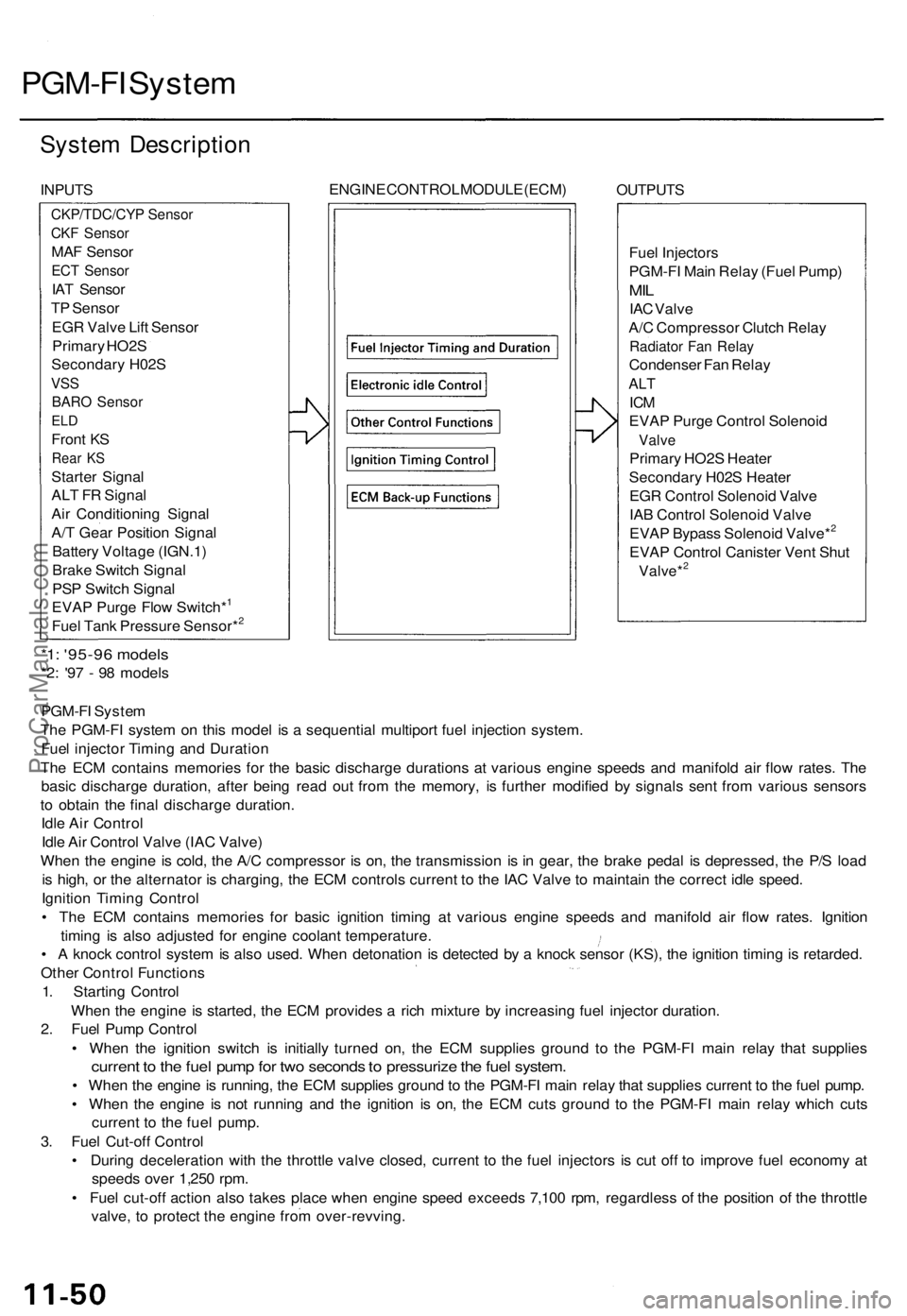
PGM-FI System
System Description
INPUTS
ENGINE CONTROL MODULE (ECM)
OUTPUTS
Fuel Injectors
PGM-FI Main Relay (Fuel Pump)
MIL
IAC Valve
A/C Compressor Clutch Relay
Radiator Fan Relay
Condenser Fan Relay
ALT
ICM
EVAP Purge Control Solenoid
Valve
Primary HO2S Heater
Secondary H02S Heater
EGR Control Solenoid Valve
IAB Control Solenoid Valve
EVAP Bypass Solenoid Valve*2
EVAP Control Canister Vent Shut
Valve*2
*1: '95-96 models
*2: '97 - 98 models
PGM-FI System
The PGM-FI system on this model is a sequential multiport fuel injection system.
Fuel injector Timing and Duration
The ECM contains memories for the basic discharge durations at various engine speeds and manifold air flow rates. The
basic discharge duration, after being read out from the memory, is further modified by signals sent from various sensors
to obtain the final discharge duration.
Idle Air Control
Idle Air Control Valve (IAC Valve)
When the engine is cold, the A/C compressor is on, the transmission is in gear, the brake pedal is depressed, the P/S load
is high, or the alternator is charging, the ECM controls current to the IAC Valve to maintain the correct idle speed.
Ignition Timing Control
• The ECM contains memories for basic ignition timing at various engine speeds and manifold air flow rates. Ignition
timing is also adjusted for engine coolant temperature.
• A knock control system is also used. When detonation is detected by a knock sensor (KS), the ignition timing is retarded.
Other Control Functions
1. Starting Control
When the engine is started, the ECM provides a rich mixture by increasing fuel injector duration.
2. Fuel Pump Control
• When the ignition switch is initially turned on, the ECM supplies ground to the PGM-FI main relay that supplies
current to the fuel pump for two seconds to pressurize the fuel system.
• When the engine is running, the ECM supplies ground to the PGM-FI main relay that supplies current to the fuel pump.
• When the engine is not running and the ignition is on, the ECM cuts ground to the PGM-FI main relay which cuts
current to the fuel pump.
3. Fuel Cut-off Control
• During deceleration with the throttle valve closed, current to the fuel injectors is cut off to improve fuel economy at
speeds over 1,250 rpm.
• Fuel cut-off action also takes place when engine speed exceeds 7,100 rpm, regardless of the position of the throttle
valve, to protect the engine from over-revving.
CKP/TDC/CYP Sensor
CKF Sensor
MAF Sensor
ECT Sensor
IAT Sensor
TP Sensor
EGR Valve Lift Sensor
Primary HO2S
Secondary H02S
VSS
BARO Sensor
ELD
Front KS
Rear KS
Starter Signal
ALT FR Signal
Air Conditioning Signal
A/T Gear Position Signal
Battery Voltage (IGN.1)
Brake Switch Signal
PSP Switch Signal
EVAP Purge Flow Switch*1
Fuel Tank Pressure Sensor*2ProCarManuals.com
Page 883 of 1771
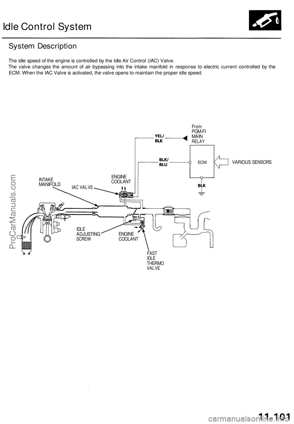
Idle Control System
System Description
The idle speed of the engine is controlled by the Idle Air Control (IAC) Valve.
The valve changes the amount of air bypassing into the intake manifold in response to electric current controlled by the
ECM. When the IAC Valve is activated, the valve opens to maintain the proper idle speed.
From
PGM-FI
MAIN
RELAY
INTAKE
MANIFOLD
VARIOUS SENSORS
FAST
IDLE
THERMO
VALVE
IDLE
ADJUSTING
SCREW
ENGINE
COOLANT
ENGINE
COOLANT
IAC VALVE
ECMProCarManuals.com
Page 917 of 1771
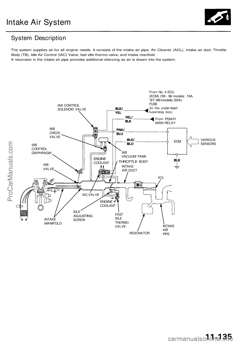
Intake Air System
System Description
The system supplies air for all engine needs. It consists of the intake air pipe, Air Cleaner (ACL), intake air duct. Throttle
Body (TB), Idle Air Control (IAC) Valve, fast idle thermo valve, and intake manifold.
A resonator in the intake air pipe provides additional silencing as air is drawn into the system.
IAB CONTROL
SOLENOID VALVE
IAB
CHECK
VALVE
IAB
CONTROL
DIAPHRAGM
From No. 4 ECU
(ECM) ('95 - 96 models: 15A,
'97-98 models: 20A)
FUSE
(in the under-dash
fuse/relay box)
From PGM-FI
MAIN RELAY
VARIOUS
SENSORS
IAB
VACUUM TANK
THROTTLE
BODY
INTAKE
AIR DUCT
ACL
INTAKE
MANIFOLD
IDLE
ADJUSTING
SCREW
FAST
IDLE
THERMO
VALVE
RESONATOR
INTAKE
AIR
PIPE
IAC VALVE
ENGINE
COOLANT
ENGINE
COOLANT
IAB
VALVE
ECMProCarManuals.com
Page 930 of 1771
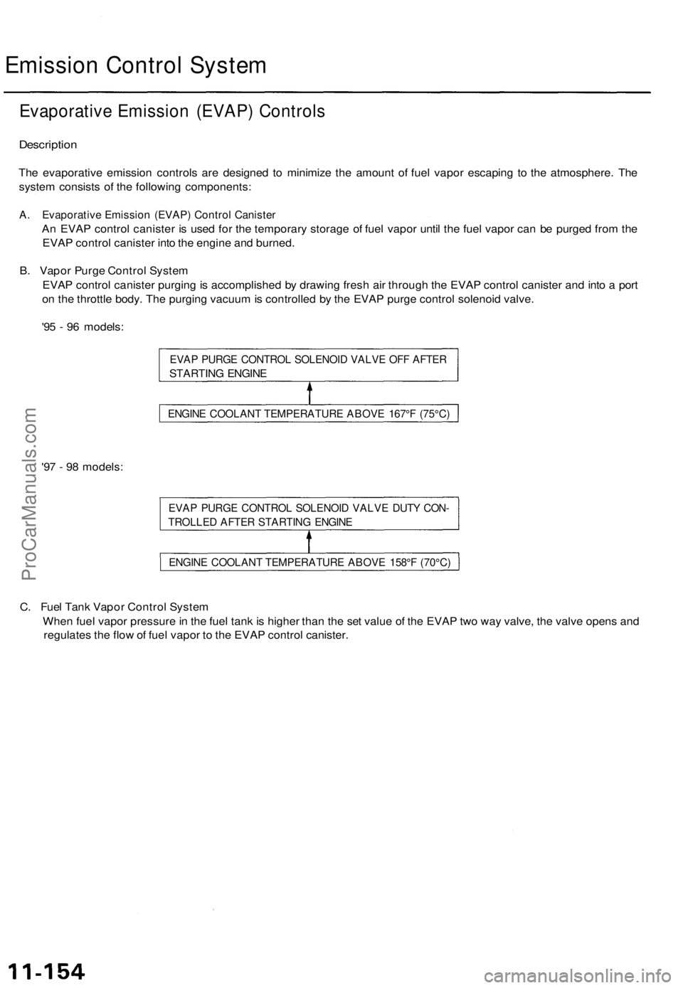
Emission Control System
Evaporative Emission (EVAP) Controls
Description
The evaporative emission controls are designed to minimize the amount of fuel vapor escaping to the atmosphere. The
system consists of the following components:
A. Evaporative Emission (EVAP) Control Canister
An EVAP control canister is used for the temporary storage of fuel vapor until the fuel vapor can be purged from the
EVAP control canister into the engine and burned.
B. Vapor Purge Control System
EVAP control canister purging is accomplished by drawing fresh air through the EVAP control canister and into a port
on the throttle body. The purging vacuum is controlled by the EVAP purge control solenoid valve.
'95 - 96 models:
EVAP PURGE CONTROL SOLENOID VALVE OFF AFTER
STARTING ENGINE
'97 - 98 models:
EVAP PURGE CONTROL SOLENOID VALVE DUTY CON-
TROLLED AFTER STARTING ENGINE
C. Fuel Tank Vapor Control System
When fuel vapor pressure in the fuel tank is higher than the set value of the EVAP two way valve, the valve opens and
regulates the flow of fuel vapor to the EVAP control canister.
ENGINE COOLANT TEMPERATURE ABOVE 167°F (75°C)
ENGINE COOLANT TEMPERATURE ABOVE 158°F (70°C)ProCarManuals.com