Page 951 of 1771
Description
The electronic control system consists of the Transmission Control Module (TCM), sensors, a linear solenoid, and four
solenoid valves.
Shift and lock-up are electronically controlled for comfortable driving under all conditions.
The TCM is located below the dashboard, behind the glove box on the passenger's side.
TCM
Linear Solenoid
Shift Control
Solenoid Valve A
Shift Control
Solenoid Valve B
Lock-up Control
Solenoid Valve A
Lock-up Control
Solenoid Valve B
Engine Speed Signal
Brake Switch Signal
Mainshaft Speed Sensor
Signal
Countershaft Speed
Sensor Signal
Vehicle Speed Sensor
Signal
Indicator Light
Self-Diagnosis Signal
Electronic Control System
Shift Control
Lock-up Control
Throttle Position
Sensor Signal
Engine Coolant
Temperature
Sensor Signal
Service Check
Connector
Barometric
Pressure Sensor
INTERLOCK
CONTROL UNIT
Self-Diagnosis
FunctionProCarManuals.com
Page 953 of 1771
Description
GRADE LOGIC CONTROL SYSTEM
How it works:
The TCM compares actual driving conditions with driving conditions memorized in the TCM, based on the input from the
vehicle speed sensor, throttle position sensor, engine coolant temperature sensor, barometric pressure sensor, brake
switch signal and shift lever position signal, to control shifting while a vehicle is ascending or descending a slope, or
reducing speed.
SENSORS
SIGNALS DETECTED
TCM
Electronic Control System (cont'd)ProCarManuals.com
Page 972 of 1771
Component Locations
BRAKE SWITCH
TRANSMISSION CONTROL
MODULE (TCM)
ENGINE CONTROL
MODULE (ECM)
THROTTLE POSITION (TP)
SENSOR
ENGINE COOLANT
TEMPERATURE (ECT)
SENSOR
LOCK-UP CONTROL SOLENOID
VALVE ASSEMBLY
MAINSHAFT SPEED SENSOR
COUNTERSHAFT SPEED
SENSOR
VEHICLE SPEED
SENSOR (VSS)
AUTOMATIC TRANSAXLE (A/T)
GEAR POSITION SWITCH
SHIFT CONTROL SOLENOID
VALVE ASSEMBLY*
LINEAR SOLENOID*
*: Located in transmission.ProCarManuals.com
Page 1497 of 1771

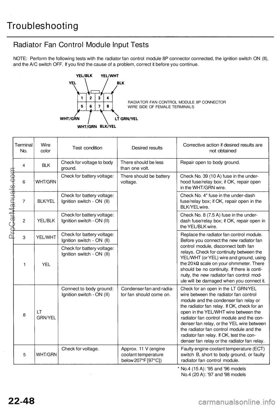
Troubleshooting
Radiator Fan Control Module Input Tests
NOTE: Perform the following tests with the radiator fan control module 8P connector connected, the ignition switch ON (II),
and the A/C switch OFF. If you find the cause of a problem, correct it before you continue.
RADIATOR FAN CONTROL MODULE 8P CONNECTOR
WIRE SIDE OF FEMALE TERMINALS
Terminal
No.
4
6
7
2
3
1
8
5
Wire
color
BLK
WHT/GRN
BLK/YEL
YEL/BLK
YEL/WHT
YEL
LT
GRN/YEL
WHT/GRN
Test condition
Check for voltage to body
ground.
Check for battery voltage:
Check for battery voltage:
Ignition switch - ON (II)
Check for battery voltage:
Ignition switch - ON (II)
Check for battery voltage:
Ignition switch - ON (II)
Check for battery voltage:
Ignition switch - ON (II)
Connect to body ground:
Ignition switch - ON (II)
Check for voltage.
Desired results
There should be less
than one volt.
There should be battery
voltage.
Condenser fan and radia-
tor fan should come on.
Approx. 11 V (engine
coolant temperature
below 207°F [97°C])
Corrective action if desired results are
not obtained
Repair open to body ground.
Check No. 39 (10 A) fuse in the under-
hood fuse/relay box; if OK, repair open
in the WHT/GRN wire.
Check No. 4* fuse in the under-dash
fuse/relay box; if OK, repair open in the
BLK/YEL wire.
Check No. 8 (7.5 A) fuse in the under-
dash fuse/relay box; if OK, repair open in
the YEL/BLK wire.
Replace the radiator fan control module.
Before you connect the new radiator fan
control module, disconnect both fan
relays. Check for continuity between the
YEL/WHT (or YEL) wire and ground, using
the 20 k scale on your ohmmeter. There
should be no continuity. If there is conti-
nuity, the new radiator fan control mod-
ule will be damaged when you connect it.
Check for an open in the LT GRN/YEL
wire between the radiator fan control
module and the condenser fan relay or
the radiator fan relay. If OK, check for an
open in the YEL/WHT wire between the
radiator fan control module and the con-
denser fan relay, or the YEL wire between
the radiator fan control module and the
radiator fan relay. If OK, test the con-
denser fan relay or the radiator fan relay.
Faulty engine coolant temperature (ECT)
switch B, short to body ground, or faulty
radiator fan control module.
* No.4 (15 A): '95 and '96 models
No.4 (20 A): '97 and '98 modelsProCarManuals.com
Page 1567 of 1771

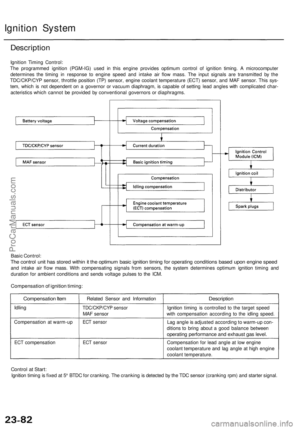
Ignition Syste m
Descriptio n
Ignition Timin g Control :
Th e programme d ignitio n (PGM-IG ) use d i n thi s engin e provide s optimu m contro l o f ignitio n timing . A microcompute r
determine s th e timin g i n respons e t o engin e spee d an d intak e ai r flo w mass . Th e inpu t signal s ar e transmitte d b y th e
TDC/CKP/CY P sensor , throttl e positio n (TP ) sensor , engine coolant temperatur e (ECT ) sensor , an d MA F sensor . Thi s sys -
tem , whic h i s no t dependen t o n a governo r o r vacuu m diaphragm , i s capabl e o f settin g lea d angle s wit h complicate d char -
acteristic s whic h canno t b e provide d b y conventiona l governor s o r diaphragms .
Basi c Control :
The contro l uni t ha s store d withi n it th e optimu m basi c ignitio n timin g fo r operatin g condition s base d upo n engin e spee d
and intak e ai r flo w mass . Wit h compensatin g signal s fro m sensors , th e syste m determine s optimu m ignitio n timin g an d
duratio n fo r ambien t condition s an d send s voltag e pulse s t o th e ICM .
Compensatio n of ignitio n timing :
Compensatio n Ite m
Idlin g
Compensatio n a t warm-u p
ECT compensatio n Relate
d Senso r an d Informatio n
TDC/CKP/CY P senso r
MAF senso r
ECT senso r
ECT senso r
Descriptio n
Ignition timin g i s controlle d t o th e targe t spee d
wit h compensatio n accordin g t o th e idlin g speed .
La g angl e is adjuste d accordin g t o warm-u p con -
dition s t o brin g abou t a goo d balanc e betwee n
operating performanc e an d exhaus t ga s level .
Compensatio n fo r lea d angl e a t lo w engin e
coolan t temperatur e an d la g angl e a t hig h engin e
coolan t temperature .
Control a t Start :
Ignitio n timin g is fixe d a t 5 ° BTD C fo r cranking . Th e crankin g is detecte d b y th e TD C senso r (crankin g rpm ) an d starte r signal .
ProCarManuals.com
Page 1578 of 1771
Charging System
Description
To improve fuel economy, the alternator control system within the ECM changes the voltage generated at the alternator in
accordance with driving conditions.
Throttle position (TP) sensor
Engine coolant temperature
(ECT) sensor
Intake air temperature (IAT)
sensor
TDC/CKP/CYP sensor
Vehicle speed sensor (VSS)
ELD
Air conditioning signal
ECM
Alternator
STARTER SWITCH ON
Generated voltage decreases from 14.0 V to 12.5 V
AND
ELECTRICAL LOAD below 15 A
and
VEHICLE SPEED between 9 mph (15 km/h) and
44 mph (70
km/h)
and
ENGINE SPEED between 1,100 rpm and 3,000 rpm
and
ENGINE COOLANT TEMPERATURE above 176°F
(80°C)
and
A/C SWITCH OFF
and
INTAKE AIR TEMPERATURE above 65°F (18°C)
AND
FUEL CUT-OFF CON-
TROL function is not
engaged.ProCarManuals.com