Page 368 of 1771
CHECK BALL
CHECK BALLS
CHECK BALL
FILTERS
CHOKE
MAIN VALVE BODY
(Sectional View)
SPRING SPECIFICATIONS
Unit: mm (in)
No.
Spring
4-3 kick-down valve spring
3-4 shift valve spring
2-3 shift valve spring
1-2 shift valve spring
CPC valve spring
Standard (New)
Wire Dia.
1.1 (0.043)
0.8(0.031)
0.8(0.031)
0.9 (0.035)
1.0(0.039)
O.D.
7.1 (0.280)
6.6 (0.260)
6.6 (0.260)
7.6 (0.299)
6.8 (0.268)
Free Length
51.3(2.020)
42.1 (1.657)
42.1 (1.657)
55.5(2.185)
34.3(1.350)
No. of Coils
22.5
22.0
22.0
24.0
14.2
CHECK BALLSProCarManuals.com
Page 390 of 1771

Countershaft
Inspection (cont'd )
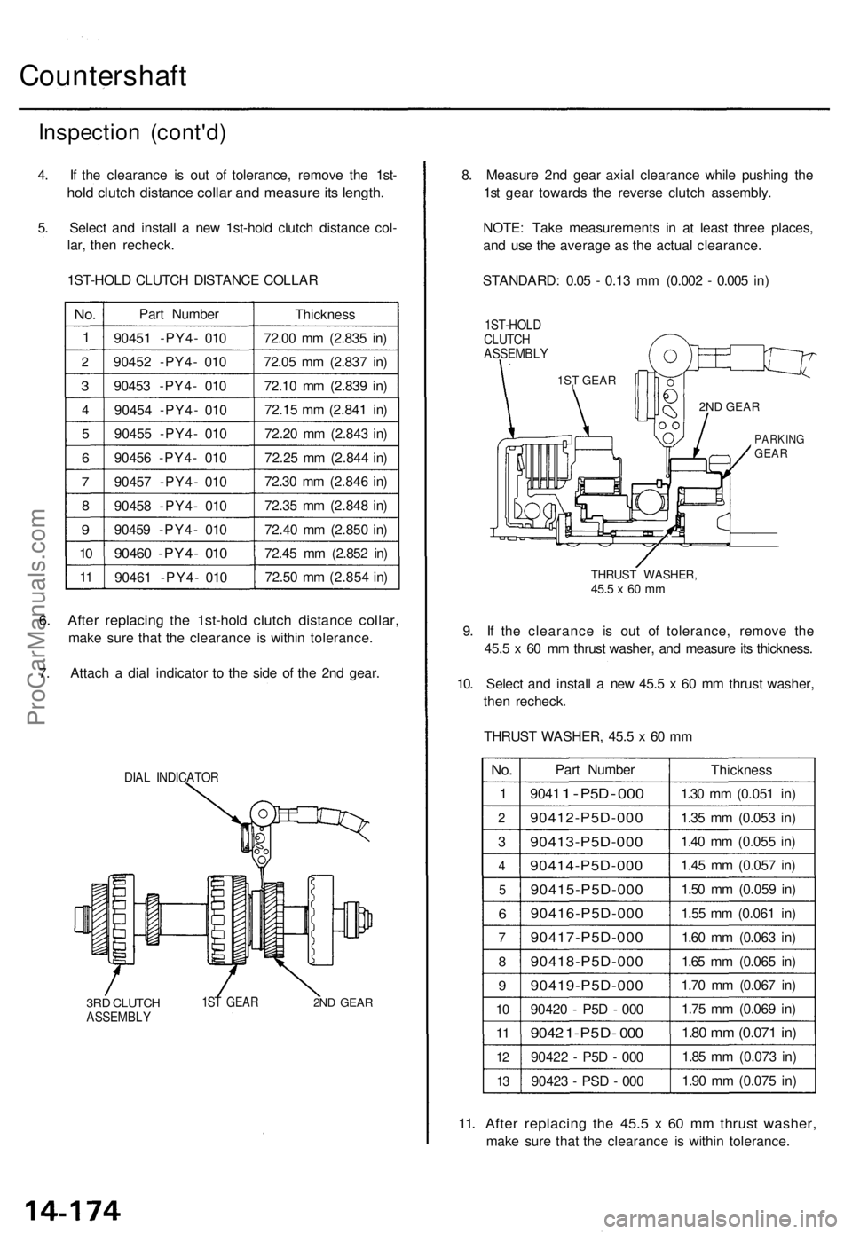
4. I f th e clearanc e i s ou t o f tolerance , remov e th e 1st -
hold clutc h distanc e colla r an d measur e it s length .
5. Selec t an d instal l a ne w 1st-hol d clutc h distanc e col -
lar , the n recheck .
1ST-HOL D CLUTC H DISTANC E COLLA R
No.
1
2
3
4
5
6
7
8
9
10
1 1
Par t Numbe r
9045 1 -PY4 - 01 0
9045 2 -PY4 - 01 0
9045 3 -PY4 - 01 0
9045 4 -PY4 - 01 0
9045 5 -PY4 - 01 0
9045 6 -PY4 - 01 0
9045 7 -PY4 - 01 0
9045 8 -PY4 - 01 0
9045 9 -PY4 - 01 0
9046 0 -PY4 - 01 0
9046 1 -PY4 - 01 0 Thicknes
s
72.0 0 m m (2.83 5 in )
72.0 5 m m (2.83 7 in )
72.1 0 m m (2.83 9 in )
72.1 5 m m (2.84 1 in )
72.2 0 m m (2.84 3 in )
72.2 5 m m (2.84 4 in )
72.3 0 m m (2.84 6 in )
72.3 5 m m (2.84 8 in )
72.4 0 m m (2.85 0 in )
72.4 5 m m (2.85 2 in )
72.5 0 m m (2.85 4 in )
6. Afte r replacin g th e 1st-hol d clutc h distanc e collar ,
make sur e tha t th e clearanc e i s withi n tolerance .
7 . Attac h a dia l indicato r t o th e sid e o f th e 2n d gear .
DIAL INDICATO R
3RD CLUTC HASSEMBL Y1ST GEA R2ND GEA R
8. Measur e 2n d gea r axia l clearanc e whil e pushin g th e
1s t gea r toward s th e revers e clutc h assembly .
NOTE : Tak e measurement s i n a t leas t thre e places ,
an d us e th e averag e a s th e actua l clearance .
STANDARD : 0.0 5 - 0.1 3 m m (0.00 2 - 0.00 5 in )
1ST-HOL D
CLUTC H
ASSEMBL Y
THRUST WASHER ,45.5 x 60 m m
9. I f th e clearanc e i s ou t of tolerance , remov e th e
45. 5 x 6 0 m m thrus t washer , an d measur e it s thickness .
10 . Selec t an d instal l a ne w 45. 5 x 6 0 m m thrus t washer ,
the n recheck .
THRUS T WASHER , 45. 5 x 60 m m
No .
1
2
3
4
5
6
7
8
9
10
11
1 2
13
Par t Numbe r
9041 1 - P5 D - 000
90412-P5D-00 0
90413-P5D-000
90414-P5D-00 0
90415-P5D-00 0
90416-P5D-000
90417-P5D-000
90418-P5D-00 0
90419-P5D-000
90420 - P5 D - 00 0
904 2 1-P5D - 00 0
9042 2 - P5 D - 00 0
9042 3 - PS D - 00 0 Thicknes
s
1.3 0 m m (0.05 1 in )
1.3 5 m m (0.05 3 in )
1.4 0 m m (0.05 5 in )
1.4 5 m m (0.05 7 in )
1.5 0 m m (0.05 9 in )
1.5 5 m m (0.06 1 in )
1.6 0 m m (0.06 3 in )
1.6 5 m m (0.06 5 in )
1.7 0 m m (0.06 7 in )
1.7 5 m m (0.06 9 in )
1.80 m m (0.07 1 in )
1.8 5 m m (0.07 3 in )
1.9 0 m m (0.07 5 in )
11. Afte r replacin g th e 45. 5 x 6 0 m m thrus t washer ,
make sur e tha t th e clearanc e i s withi n tolerance .
PARKINGGEAR
2ND GEAR
1ST GEAR
I
ProCarManuals.com
Page 485 of 1771

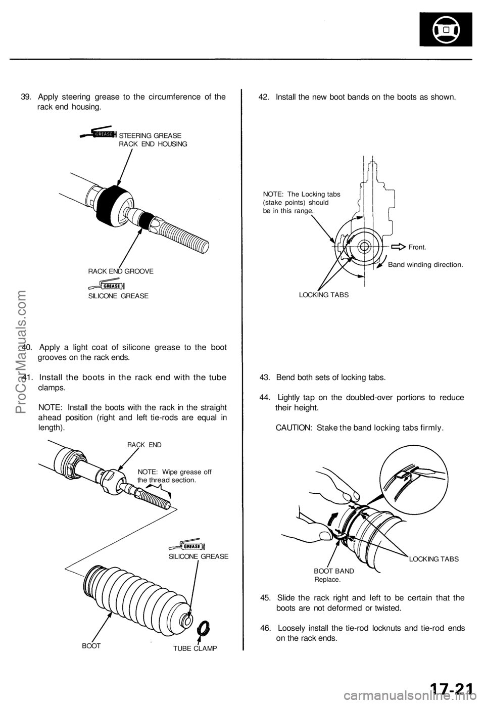
39. Appl y steerin g greas e t o th e circumferenc e o f th e
rac k en d housing .
STEERIN G GREAS E
RAC K EN D HOUSIN G
RAC K EN D GROOV E
40. Appl y a ligh t coa t o f silicon e greas e t o th e boo t
groove s o n th e rac k ends .
41. Instal l th e boot s i n th e rac k en d wit h th e tub e
clamps .
NOTE : Instal l th e boot s wit h th e rac k i n th e straigh t
ahea d positio n (righ t an d lef t tie-rod s ar e equa l i n
length) .
NOTE: Wip e greas e of fthe threa d section .
SILICON E GREAS E
BOO T
TUBE CLAM P
42. Instal l th e ne w boo t band s o n th e boot s a s shown .
NOTE: Th e Lockin g tab s
(stak e points ) shoul d
b e i n thi s range .
LOCKIN G TAB S
43. Ben d bot h set s o f lockin g tabs .
44 . Lightl y ta p o n th e doubled-ove r portion s t o reduc e
their height .
CAUTION : Stak e th e ban d lockin g tab s firmly .
LOCKIN G TAB S
BOO T BAN D
Replace .
45. Slid e th e rac k righ t an d lef t t o b e certai n tha t th e
boot s ar e no t deforme d o r twisted .
46 . Loosel y instal l th e tie-ro d locknut s an d tie-ro d end s
o n th e rac k ends .
SILICON E GREAS E
Band windin g direction .
Front.
RACK EN D
ProCarManuals.com
Page 591 of 1771
NOTE: T o sea t ne w brushe s afte r installin g the m in thei r
holders , sli p a stri p o f #50 0 o r #60 0 sandpaper , wit h th e
gri t sid e up , ove r th e commutator , an d smoothl y rotat e
th e armature . Th e contac t surfac e o f th e brushe s wil l b e
sande d t o th e sam e contou r a s th e commutator .
2
. Inser t th e brus h int o th e brus h holder , an d brin g th e
brus h int o contac t wit h th e commutator , the n attac h
a sprin g scal e to th e spring . Measur e th e sprin g ten -
sio n a t th e momen t th e sprin g lift s of f th e brush .
Startin g Syste m
Starter Brus h Holde r Tes t
1. Chec k tha t ther e is n o continuit y betwee n th e an d
brush holders . I f ther e i s continuity , replac e th e
brus h holde r assembly .
Starter Brus h Inspectio n
Measure th e brus h length . I f i t i s no t withi n th e servic e
limit, replac e th e brus h holde r assembly .
Brush Lengt h
ProCarManuals.com
Page 1045 of 1771
5. If the clearance is out of tolerance, remove the dis-
tance collar and measure its length.
Length
6. Select and install a new distance collar, then recheck.
DISTANCE COLLAR, 35mm
No.
1
2
3
4
5
6
7
8
9
10
Part Number
90501 - PW7 - 000
90502 - PW7 - 000
90503 - PW7 - 000
90504 - PW7 - 000
90505 - PW7 - 000
90506 - PW7 - 000
90507 - PW7 - 000
90508 - PW7 - 000
90509 - PW7 - 000
90510-PW7- 000
Thickness
65.65 mm (2.585 in)
65.70 mm (2.587 in)
65.75 mm (2.589 in)
65.80 mm (2.591 in)
65.85 mm (2.593 in)
65.90 mm (2.594 in)
65.95 mm (2.596 in)
66.00 mm (2.598 in)
66.05 mm (2.600 in)
66.10 mm (2.602 in)
7. After replacing the distance collar, make sure that
the clearance is within tolerance.ProCarManuals.com
Page 1067 of 1771
Parking Brake Roller Rod
Adjustment
1. Move the detent lever to the position.
2. Measure the clearance between the parking brake
roller rod and the transmission housing as shown.
STANDARD: 3.8 - 4.3 mm (0.15 - 0.17 in)
Measuring Clearance
ROLLER
TRANSMISSION
HOUSING
DETENT LEVER
ROLLER ROD
3. If the clearance is out of tolerance, select and install
a new parking brake roller rod.
PARKING BRAKE ROLLER ROD
Mark
L Length
PARKING BRAKE ROLLER ROD
Mark
1 or None
2
0
3
Part Number
24550 -PW4- 010
24560 -PW4- 010
24580 -PW4- 010
24590 - PW4 - 000
Length "L"
36.0 mm (1.417 in)
35.6 mm (1.402 in)
36.4 mm (1.433 in)
36.2 mm (1.425 in)
4. After replacing the parking brake roller rod, make
sure that the clearance is within tolerance.ProCarManuals.com
Page 1080 of 1771
Transmission
Installation (cont'd)
8. Install the mid mount spacer and transmission mid
mounts while raising the transmission with a jack.
TRANSMISSION
MID MOUNT
SPACER
Install in this
direction.
MID MOUNT
10 x
1.25
mm
38 N-m (3.9 kgf-m,
28 Ibf-ft)
9. Tighten the bolts using an offset wrench and a torque
wrench as shown.
MID MOUNTS
OFFSET WRENCH
(Commercially available)
TORQUE WRENCH
NOTE: When tightening the bolts using an offset wrench
and a torque wrench, the tightening torque value differs
from torque specification according to a torque wrench.
Before tightening the bolts, calculate actual torque value
by following formula.
TORQUE
WRENCH
OFFSET WRENCH
Example:
Torque Specification: 38 N-m (3.9 kgf-m, 28 Ibf-ft)
Effective Length of Torque Wrench: 0.345 (m)
Effective Length of Offset Wrench: 0.13 (m)
WASHER
MID MOUNT NUTS
10 x
1.25
mm
43 N-m (4.4 kgf-m, 32 Ibf-ft)
10. Install the mid mount nuts.ProCarManuals.com
Page 1209 of 1771

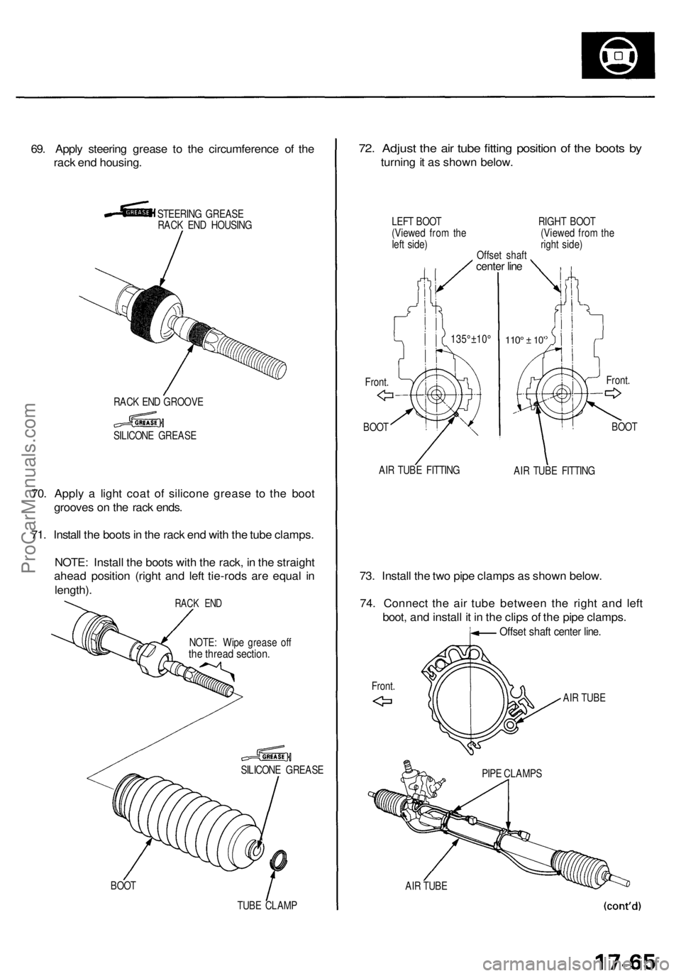
69. Appl y steerin g greas e t o th e circumferenc e o f th e
rac k en d housing .
STEERIN G GREAS E
RAC K EN D HOUSIN G
RAC K EN D GROOV E
SILICON E GREAS E
70. Appl y a ligh t coa t of silicon e greas e t o th e boo t
groove s o n th e rac k ends .
71 . Instal l th e boot s in th e rac k en d wit h th e tub e clamps .
NOTE : Instal l th e boot s wit h th e rack , i n th e straigh t
ahea d positio n (righ t an d lef t tie-rod s ar e equa l i n
length) .
NOTE: Wip e greas e of fthe threa d section .
SILICON E GREAS E
BOO T
TUBE CLAM P
72. Adjus t th e ai r tub e fittin g positio n o f th e boot s b y
turnin g it a s show n below .
LEFT BOO T RIGH T BOO T
(Viewe d fro m th e (Viewe d fro m th e
lef t side ) righ t side )
Offse t shaf t
center lin e
135°±10 °
BOO T110° ± 10 '
BOO T
AI R TUB E FITTIN G
AIR TUB E FITTIN G
73. Instal l th e tw o pip e clamp s a s show n below .
74 . Connec t th e ai r tub e betwee n th e righ t an d lef t
boot , an d instal l i t i n th e clip s o f th e pip e clamps .
Offset shaf t cente r line .
AIR TUB E
AI R TUB E PIP
E CLAMP S
Front
. Front
.
Front .
RACK EN D
ProCarManuals.com