1994 JEEP CHEROKEE wheel bolt torque
[x] Cancel search: wheel bolt torquePage 1055 of 1784
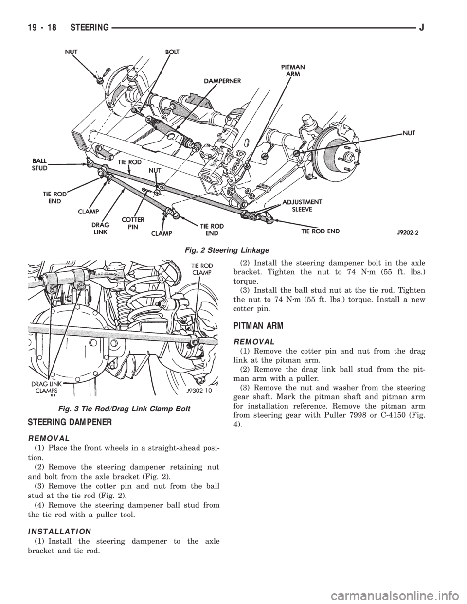
STEERING DAMPENER
REMOVAL
(1) Place the front wheels in a straight-ahead posi-
tion.
(2) Remove the steering dampener retaining nut
and bolt from the axle bracket (Fig. 2).
(3) Remove the cotter pin and nut from the ball
stud at the tie rod (Fig. 2).
(4) Remove the steering dampener ball stud from
the tie rod with a puller tool.
INSTALLATION
(1) Install the steering dampener to the axle
bracket and tie rod.(2) Install the steering dampener bolt in the axle
bracket. Tighten the nut to 74 Nzm (55 ft. lbs.)
torque.
(3) Install the ball stud nut at the tie rod. Tighten
the nut to 74 Nzm (55 ft. lbs.) torque. Install a new
cotter pin.
PITMAN ARM
REMOVAL
(1) Remove the cotter pin and nut from the drag
link at the pitman arm.
(2) Remove the drag link ball stud from the pit-
man arm with a puller.
(3) Remove the nut and washer from the steering
gear shaft. Mark the pitman shaft and pitman arm
for installation reference. Remove the pitman arm
from steering gear with Puller 7998 or C-4150 (Fig.
4).
Fig. 2 Steering Linkage
Fig. 3 Tie Rod/Drag Link Clamp Bolt
19 - 18 STEERINGJ
Page 1058 of 1784
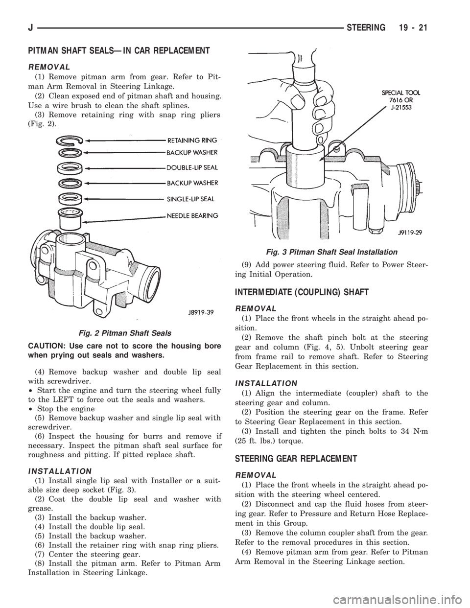
PITMAN SHAFT SEALSÐIN CAR REPLACEMENT
REMOVAL
(1) Remove pitman arm from gear. Refer to Pit-
man Arm Removal in Steering Linkage.
(2) Clean exposed end of pitman shaft and housing.
Use a wire brush to clean the shaft splines.
(3) Remove retaining ring with snap ring pliers
(Fig. 2).
CAUTION: Use care not to score the housing bore
when prying out seals and washers.
(4) Remove backup washer and double lip seal
with screwdriver.
²Start the engine and turn the steering wheel fully
to the LEFT to force out the seals and washers.
²Stop the engine
(5) Remove backup washer and single lip seal with
screwdriver.
(6) Inspect the housing for burrs and remove if
necessary. Inspect the pitman shaft seal surface for
roughness and pitting. If pitted replace shaft.
INSTALLATION
(1) Install single lip seal with Installer or a suit-
able size deep socket (Fig. 3).
(2) Coat the double lip seal and washer with
grease.
(3) Install the backup washer.
(4) Install the double lip seal.
(5) Install the backup washer.
(6) Install the retainer ring with snap ring pliers.
(7) Center the steering gear.
(8) Install the pitman arm. Refer to Pitman Arm
Installation in Steering Linkage.(9) Add power steering fluid. Refer to Power Steer-
ing Initial Operation.
INTERMEDIATE (COUPLING) SHAFT
REMOVAL
(1) Place the front wheels in the straight ahead po-
sition.
(2) Remove the shaft pinch bolt at the steering
gear and column (Fig. 4, 5). Unbolt steering gear
from frame rail to remove shaft. Refer to Steering
Gear Replacement in this section.
INSTALLATION
(1) Align the intermediate (coupler) shaft to the
steering gear and column.
(2) Position the steering gear on the frame. Refer
to Steering Gear Replacement in this section.
(3) Install and tighten the pinch bolts to 34 Nzm
(25 ft. lbs.) torque.
STEERING GEAR REPLACEMENT
REMOVAL
(1) Place the front wheels in the straight ahead po-
sition with the steering wheel centered.
(2) Disconnect and cap the fluid hoses from steer-
ing gear. Refer to Pressure and Return Hose Replace-
ment in this Group.
(3) Remove the column coupler shaft from the gear.
Refer to the removal procedures in this section.
(4) Remove pitman arm from gear. Refer to Pitman
Arm Removal in the Steering Linkage section.
Fig. 2 Pitman Shaft Seals
Fig. 3 Pitman Shaft Seal Installation
JSTEERING 19 - 21
Page 1074 of 1784
(2) Wrap a single layer of plastic tape around the
pitman shaft threads and splines. This will protect
the replacement seals during installation.
(3) Install the seal with a suitable size socket.
(4) Remove the tape from the shaft.
(5) Center the steering gear.
(6) Align and install the pitman arm.
(7) Install the washer and retaining nut on the pit-
man shaft. Tighten the nut to 251 Nb1m (185 ft. lbs.)
torque.
GEAR ADJUSTMENTS IN VEHICLE
REMOVE
(1) Raise and support the vehicle.
(2) Mark the pitman shaft and pitman arm for in-
stallation reference. Remove the pitman arm from
the shaft.
(3) Loosen the adjuster lock nut then back the ad-
juster plug off 1/4 turn.
(4) Remove the steering wheel horn pad.
(5) Turn the steering wheel in one direction until
stopped by the gear. Then turn back 1/2 turn.
CAUTION: Do not turn the steering wheel hard
against the internal stops when the linkage is re-
moved. This could result in damage to the recircu-
lating ball guides.
MEASURE
Place a low calibration (50 in. lbs.) torque wrench
and socket on the steering wheel nut. Rotate the
wrench and nut through a 90 degree arc (1/4 turn).
This will measure the worm shaft bearing preload.
ADJUST WORMSHAFT BEARING PRELOAD
TORQUE
(1) Adjust the preload by tightening the adjuster
plug. The preload should be 0.6 to 1 Nzm(5to8in.
lbs.) torque.
Steering column/shaft misalignment or damage will
increase the amount of torque required to rotate the
steering wheel. If the rotating torque is exceptionally
high, inspect the steering column/shaft alignment. If
the alignment is correct, remove the steering gear,
determine the cause of the high preload torque, and
repair as necessary.
(2) Tighten the adjuster locknut to 68 Nzm (50 ft.
lbs.) torque. Measure the preload torque. If neces-
sary, adjust the preload torque again.
ADJUST OVERCENTER DRAG TORQUE
(1) Turn the steering wheel from one stop to the
other and count the total numbers of turns. Turn the
wheel back in reverse direction 1/2 the total number
of turns to center the steering gear.
(2) Turn the over center adjusting screw in to re-
move all lash between the ball nut and pitman shaftsector teeth. Hold the adjustment screw and tighten
the lock nut to 34 Nzm (25 ft. lbs.) torque.
(3) Check the torque at the steering wheel by tak-
ing the highest reading as the wheel is turned
through the center position.
(4) The overcenter drag torque should be 0.5 to 1
Nzm (4 to 10 in. lbs.).
(5) If necessary, loosen the lock nut and adjust the
over center adjuster screw to obtain the proper
torque. Re-tighten the lock nut to the lock nut.
(6) After tightening the locknut, measure the over-
center drag torque again and readjust the torque, if
necessary.
INSTALL
(1) Align the installation reference marks and in-
stall the pitman arm.
(2) Install and tighten the pitman shaft nut and
washer to 251 Nzm (185 ft. lbs.) torque.
(3) Install the horn button.
GEAR DISASSEMBLY
(1) Rotate the wormshaft from stop-to-stop and
count the number of rotations. Rotate the wormshaft
in the reverse direction 1/2 of the total number of ro-
tations to center it and the ball nut.
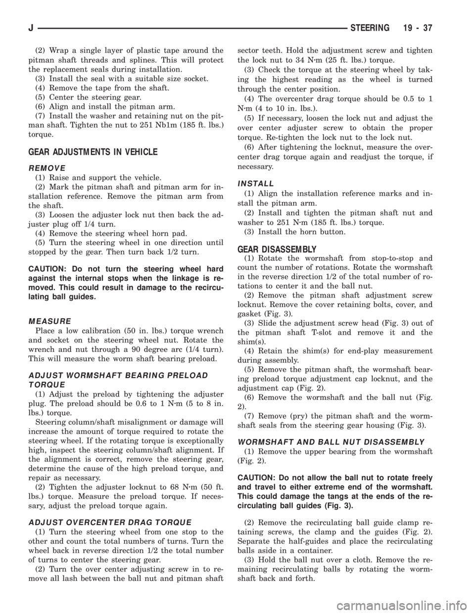
(2) Remove the pitman shaft adjustment screw
locknut. Remove the cover retaining bolts, cover, and
gasket (Fig. 3).
(3) Slide the adjustment screw head (Fig. 3) out of
the pitman shaft T-slot and remove it and the
shim(s).
(4) Retain the shim(s) for end-play measurement
during assembly.
(5) Remove the pitman shaft, the wormshaft bear-
ing preload torque adjustment cap locknut, and the
adjustment cap (Fig. 2).
(6) Remove the wormshaft and the ball nut (Fig.
2).
(7) Remove (pry) the pitman shaft and the worm-
shaft seals from the steering gear housing (Fig. 3).
WORMSHAFT AND BALL NUT DISASSEMBLY
(1) Remove the upper bearing from the wormshaft
(Fig. 2).
CAUTION: Do not allow the ball nut to rotate freely
and travel to either extreme end of the wormshaft.
This could damage the tangs at the ends of the re-
circulating ball guides (Fig. 3).
(2) Remove the recirculating ball guide clamp re-
taining screws, the clamp and the guides (Fig. 2).
Separate the half-guides and place the recirculating
balls aside in a container.
(3) Hold the ball nut over a cloth. Remove the re-
maining recirculating balls by rotating the worm-
shaft back and forth.
JSTEERING 19 - 37
Page 1080 of 1784
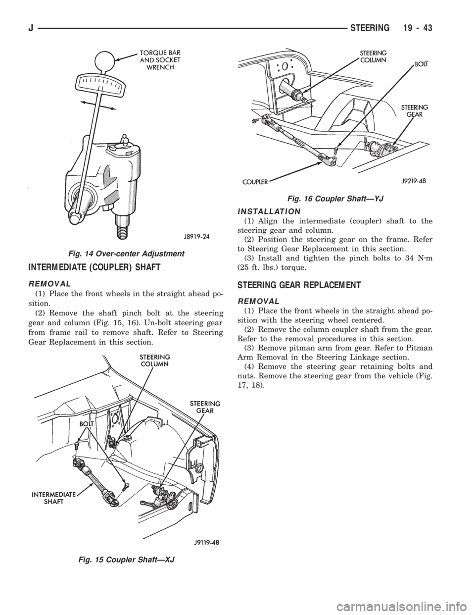
INTERMEDIATE (COUPLER) SHAFT
REMOVAL
(1) Place the front wheels in the straight ahead po-
sition.
(2) Remove the shaft pinch bolt at the steering
gear and column (Fig. 15, 16). Un-bolt steering gear
from frame rail to remove shaft. Refer to Steering
Gear Replacement in this section.
INSTALLATION
(1) Align the intermediate (coupler) shaft to the
steering gear and column.
(2) Position the steering gear on the frame. Refer
to Steering Gear Replacement in this section.
(3) Install and tighten the pinch bolts to 34 Nzm
(25 ft. lbs.) torque.
STEERING GEAR REPLACEMENT
REMOVAL
(1) Place the front wheels in the straight ahead po-
sition with the steering wheel centered.
(2) Remove the column coupler shaft from the gear.
Refer to the removal procedures in this section.
(3) Remove pitman arm from gear. Refer to Pitman
Arm Removal in the Steering Linkage section.
(4) Remove the steering gear retaining bolts and
nuts. Remove the steering gear from the vehicle (Fig.
17, 18).
Fig. 14 Over-center Adjustment
Fig. 15 Coupler ShaftÐXJ
Fig. 16 Coupler ShaftÐYJ
JSTEERING 19 - 43
Page 1085 of 1784
(11) Disconnect the following items from the steer-
ing column connectors:
²Ignition switch wire harness
²Dimmer switch wire harness
²Turn signal switch wire harness
²Windshield wiper wire harness
²Cruise control wire harness (if equipped)
²Park-lock cable (if equipped)
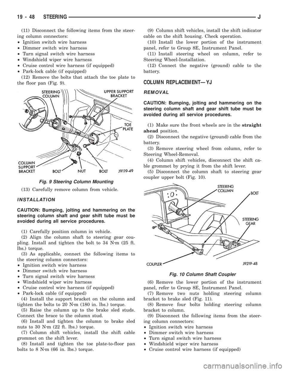
(12) Remove the bolts that attach the toe plate to
the floor pan (Fig. 9).
(13) Carefully remove column from vehicle.
INSTALLATION
CAUTION: Bumping, jolting and hammering on the
steering column shaft and gear shift tube must be
avoided during all service procedures.
(1) Carefully position column in vehicle.
(2) Align the column shaft to steering gear cou-
pling. Install and tighten the bolt to 34 Nzm (25 ft.
lbs.) torque.
(3) As applicable, connect the following items to
the steering column connectors:
²Ignition switch wire harness
²Dimmer switch wire harness
²Turn signal switch wire harness
²Windshield wiper wire harness
²Cruise control wire harness (if equipped)
²Park-lock cable (if equipped)
(4) Install the support bracket on the column and
tighten the bolts to 20 Nzm (180 in. lbs.) torque.
(5) Raise the column up to the brake sled studs.
Connect the brace to the column stud.
(6) Install and tighten the column to brake sled
nuts to 30 Nzm (22 ft. lbs.) torque.
(7) Column shift vehicles, install the shift cable
grommet on the shift lever.
(8) Install and tighten the toe plate-to-floor pan
bolts to 8 Nzm (66 in. lbs.) torque.(9) Column shift vehicles, install the shift indicator
cable on the shift housing. Check operation.
(10) Install the lower portion of the instrument
panel, refer to Group 8E, Instrument Panel.
(11) Install steering wheel on column, refer to
Steering Wheel-Installation.
(12) Connect the negative (ground) cable to the
battery.
COLUMN REPLACEMENTÐYJ
REMOVAL
CAUTION: Bumping, jolting and hammering on the
steering column shaft and gear shift tube must be
avoided during all service procedures.
(1) Make sure the front wheels are in thestraight
aheadposition.
(2) Disconnect the negative (ground) cable from the
battery.
(3) Remove steering wheel from column, refer to
Steering Wheel-Removal.
(4) Column shift vehicles, disconnect the shift ca-
ble grommet by prying it from the shift lever.
(5) Disconnect the column shaft to steering gear
coupler upper bolt (Fig. 10).
(6) Remove the lower portion of the instrument
panel, refer to Group 8E, Instrument Panel.
(7) Remove two nuts holding steering column
bracket to brake sled (Fig. 11).
(8) Remove four bolts holding steering column
bracket to column.
(9) Disconnect the following items from the steer-
ing column connectors:
²Ignition switch wire harness
²Dimmer switch wire harness
²Turn signal switch wire harness
²Windshield wiper wire harness
²Cruise control wire harness (if equipped)
Fig. 9 Steering Column Mounting
Fig. 10 Column Shaft Coupler
19 - 48 STEERINGJ
Page 1086 of 1784
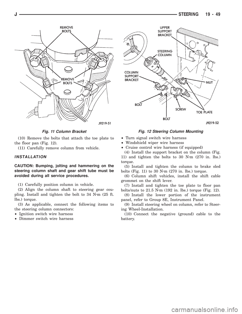
(10) Remove the bolts that attach the toe plate to
the floor pan (Fig. 12).
(11) Carefully remove column from vehicle.
INSTALLATION
CAUTION: Bumping, jolting and hammering on the
steering column shaft and gear shift tube must be
avoided during all service procedures.
(1) Carefully position column in vehicle.
(2) Align the column shaft to steering gear cou-
pling. Install and tighten the bolt to 34 Nzm (25 ft.
lbs.) torque.
(3) As applicable, connect the following items to
the steering column connectors:
²Ignition switch wire harness
²Dimmer switch wire harness²Turn signal switch wire harness
²Windshield wiper wire harness
²Cruise control wire harness (if equipped)
(4) Install the support bracket on the column (Fig.
11) and tighten the bolts to 30 Nzm (270 in. lbs.)
torque.
(5) Install and tighten the column to brake sled
bolts (Fig. 11) to 30 Nzm (270 in. lbs.) torque.
(6) Column shift vehicles, install the shift cable
grommet on the shift lever.
(7) Install and tighten the toe plate to floor pan
bolts/nuts to 21.5 Nzm (192 in. lbs.) torque (Fig. 12).
(8) Install the lower portion of the instrument
panel, refer to Group 8E, Instrument Panel.
(9) Install steering wheel on column, refer to Steer-
ing Wheel-Installation.
(10) Connect the negative (ground) cable to the
battery.
Fig. 11 Column BracketFig. 12 Steering Column Mounting
JSTEERING 19 - 49
Page 1116 of 1784
(12) Align transfer case and transmission shafts
and install transfer case. Tighten transfer case-to-
transmission nuts/bolts to 35 Nzm (26 ft. lbs.) torque.
(13) Remove jack stand from under engine and re-
position jack under transmission. Then remove trans-
mission jack.
(14) Connect transfer case vent hose and shift link-
age. Check and adjust linkage if necessary.
(15) Connect transmission and transfer case vent
hoses.
(16) Connect backup light switch wires.
(17) Connect vehicle speed sensor wires.
(18) Install and connect crankshaft position sensor
if equipped.
(19) Install rear crossmember, or skid plate (Fig. 5).
On XJ, tighten crossmember-to-frame bolts to 41 Nzm
(31 ft. lbs.) torque. Then tighten transmission-to-rear
support bolts/nuts to 45 Nzm (33 ft. lbs.) torque. On YJ,
tighten bolts/nuts to indicated torque (Fig. 5).
(20) Align and install front/rear propeller shafts.
Tighten shaft U-joint clamp bolts to 19 Nzm (170 in.
lbs.) torque.
(21) On XJ, install skid plate, if removed. Tighten
bolts to 42 Nzm (31 ft. lbs.) torque. Tighten stud nuts
to 17 Nzm (150 in. lbs.) torque.
(22) Top off transmission and transfer case lubri-
cant levels.
(23) Lower vehicle.
TRANSMISSION DISASSEMBLY AND OVERHAUL
ADAPTER HOUSING AND FRONT BEARING
RETAINER REMOVAL
(1) Drain transmission lubricant.
(2) Remove concentric bearing.
(3) Remove clutch housing bolts and remove housing.
(4) On 2-wheel drive models, remove vehicle speed
sensor, speedometer adapter and speedometer driven
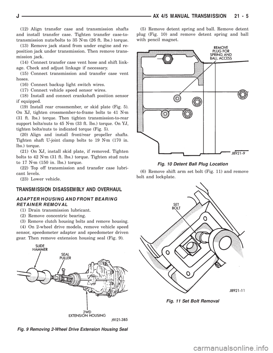
gear. Then remove extension housing seal (Fig. 9).(5) Remove detent spring and ball. Remove detent
plug (Fig. 10) and remove detent spring and ball
with pencil magnet.
(6) Remove shift arm set bolt (Fig. 11) and remove
bolt and lockplate.
Fig. 10 Detent Ball Plug Location
Fig. 11 Set Bolt Removal
Fig. 9 Removing 2-Wheel Drive Extension Housing Seal
JAX 4/5 MANUAL TRANSMISSION 21 - 5
Page 1141 of 1784
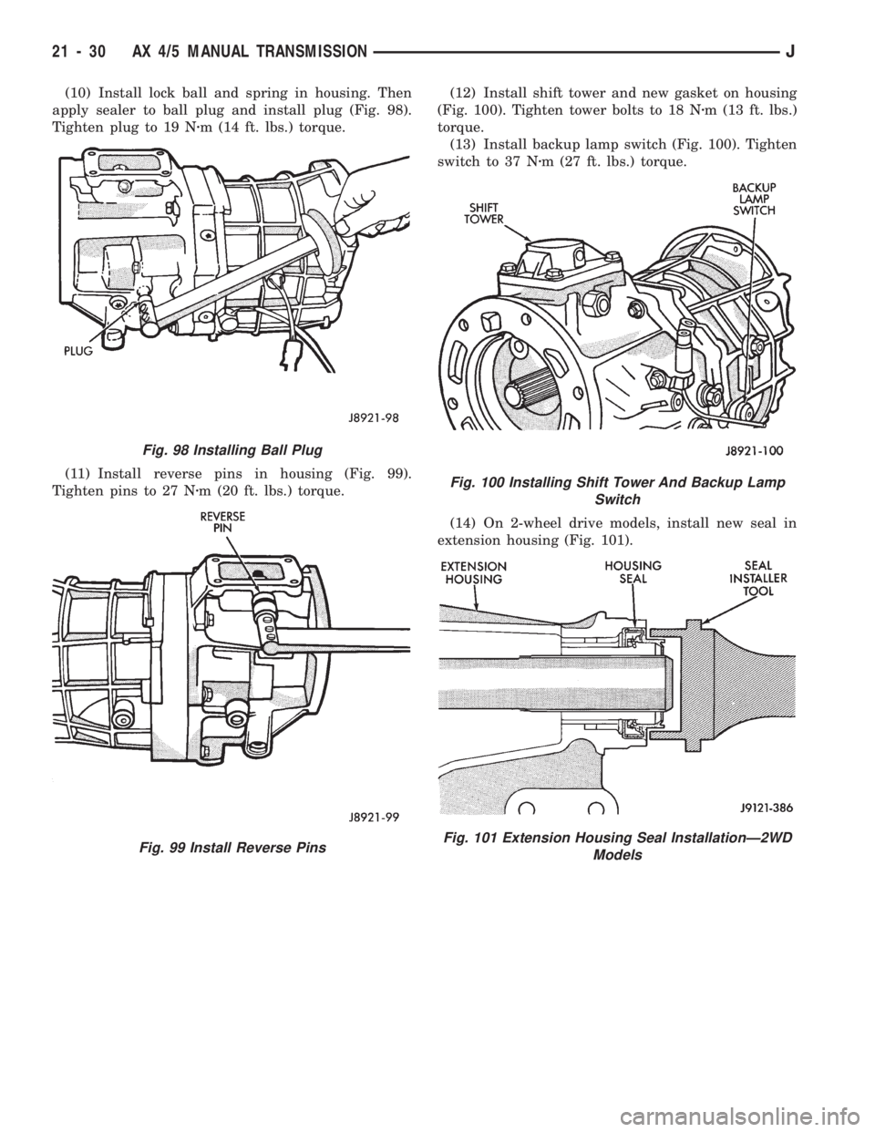
(10) Install lock ball and spring in housing. Then
apply sealer to ball plug and install plug (Fig. 98).
Tighten plug to 19 Nzm (14 ft. lbs.) torque.
(11) Install reverse pins in housing (Fig. 99).
Tighten pins to 27 Nzm (20 ft. lbs.) torque.(12) Install shift tower and new gasket on housing
(Fig. 100). Tighten tower bolts to 18 Nzm (13 ft. lbs.)
torque.
(13) Install backup lamp switch (Fig. 100). Tighten
switch to 37 Nzm (27 ft. lbs.) torque.
(14) On 2-wheel drive models, install new seal in
extension housing (Fig. 101).
Fig. 98 Installing Ball Plug
Fig. 99 Install Reverse Pins
Fig. 100 Installing Shift Tower And Backup Lamp
Switch
Fig. 101 Extension Housing Seal InstallationÐ2WD
Models
21 - 30 AX 4/5 MANUAL TRANSMISSIONJ