1994 JEEP CHEROKEE remove seats
[x] Cancel search: remove seatsPage 1584 of 1784
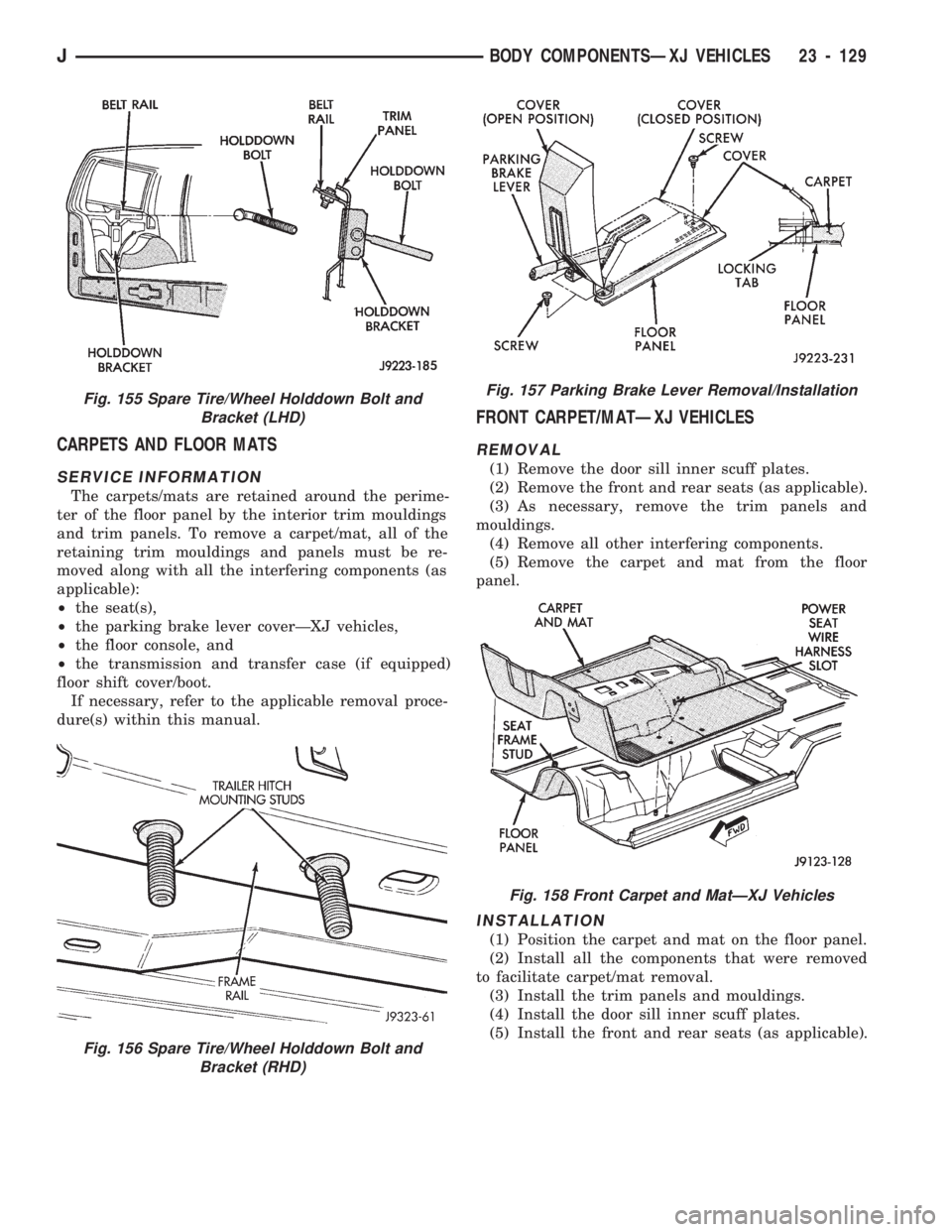
CARPETS AND FLOOR MATS
SERVICE INFORMATION
The carpets/mats are retained around the perime-
ter of the floor panel by the interior trim mouldings
and trim panels. To remove a carpet/mat, all of the
retaining trim mouldings and panels must be re-
moved along with all the interfering components (as
applicable):
²the seat(s),
²the parking brake lever coverÐXJ vehicles,
²the floor console, and
²the transmission and transfer case (if equipped)
floor shift cover/boot.
If necessary, refer to the applicable removal proce-
dure(s) within this manual.
FRONT CARPET/MATÐXJ VEHICLES
REMOVAL
(1) Remove the door sill inner scuff plates.
(2) Remove the front and rear seats (as applicable).
(3) As necessary, remove the trim panels and
mouldings.
(4) Remove all other interfering components.
(5) Remove the carpet and mat from the floor
panel.
INSTALLATION
(1) Position the carpet and mat on the floor panel.
(2) Install all the components that were removed
to facilitate carpet/mat removal.
(3) Install the trim panels and mouldings.
(4) Install the door sill inner scuff plates.
(5) Install the front and rear seats (as applicable).
Fig. 156 Spare Tire/Wheel Holddown Bolt and
Bracket (RHD)
Fig. 155 Spare Tire/Wheel Holddown Bolt and
Bracket (LHD)Fig. 157 Parking Brake Lever Removal/Installation
Fig. 158 Front Carpet and MatÐXJ Vehicles
JBODY COMPONENTSÐXJ VEHICLES 23 - 129
Page 1586 of 1784
(5) Install all the components that were removed
to facilitate carpet and mat removal.
(6) Install the trim panels and mouldings.
(7) Install the cargo tie-down footman loops on the
carpet with replacement rivets.
(8) Position the liftgate scuff plate and latch
striker on the carpet and cross sill. Install and
tighten the scuff plate screws to 1 Nzm (11 in-lbs)
torque. Tighten the latch striker screws to 30 Nzm
(22 ft-lbs) torque.
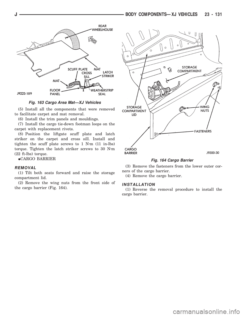
ICARGO BARRIER
REMOVAL
(1) Tilt both seats forward and raise the storage
compartment lid.
(2) Remove the wing nuts from the front side of
the cargo barrier (Fig. 164).(3) Remove the fasteners from the lower outer cor-
ners of the cargo barrier.
(4) Remove the cargo barrier.
INSTALLATION
(1) Reverse the removal procedure to install the
cargo barrier.
Fig. 164 Cargo Barrier
Fig. 163 Cargo Area MatÐXJ Vehicles
JBODY COMPONENTSÐXJ VEHICLES 23 - 131
Page 1645 of 1784
INTERIOR COMPONENTS
INDEX
page page
Carpet/Floor Mats....................... 198
Floor Consoles......................... 197
Front Shoulder Belts..................... 196
Glove Box............................. 194
Instrument Cluster and Gauge Housings...... 190
Instrument Cluster Bezel.................. 191Instrument Panel........................ 190
Instrument Panel Components.............. 191
Instrument Panel Service.................. 192
Rear Shoulder Belts..................... 196
Seats................................ 195
Sunvisors............................. 196
INSTRUMENT PANEL
SERVICE INFORMATION
The instrument panel is constructed of sheet metal
and is attached to cowl panel with screws. The in-
strument panel and defroster grille pad is attached
to the instrument panel with screws.
INSTRUMENT CLUSTER AND GAUGE HOUSINGS
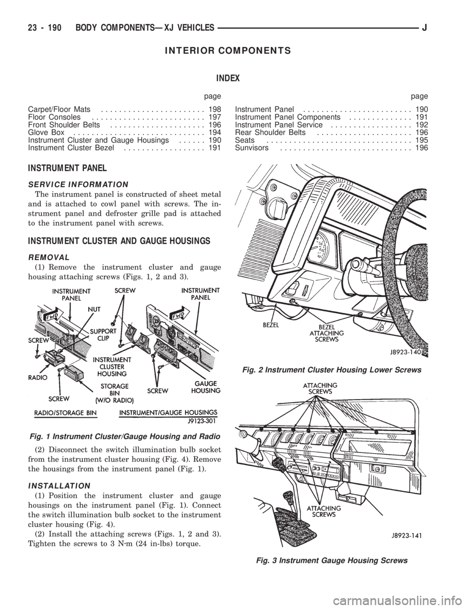
REMOVAL
(1) Remove the instrument cluster and gauge
housing attaching screws (Figs. 1, 2 and 3).
(2) Disconnect the switch illumination bulb socket
from the instrument cluster housing (Fig. 4). Remove
the housings from the instrument panel (Fig. 1).
INSTALLATION
(1) Position the instrument cluster and gauge
housings on the instrument panel (Fig. 1). Connect
the switch illumination bulb socket to the instrument
cluster housing (Fig. 4).
(2) Install the attaching screws (Figs. 1, 2 and 3).
Tighten the screws to 3 Nzm (24 in-lbs) torque.
Fig. 2 Instrument Cluster Housing Lower Screws
Fig. 3 Instrument Gauge Housing Screws
Fig. 1 Instrument Cluster/Gauge Housing and Radio
23 - 190 BODY COMPONENTSÐXJ VEHICLESJ
Page 1650 of 1784
(3) If necessary, remove the retaining screws and
the hinge from the glove box door.
INSTALLATION
(1) If removed, install the hinge on the glove box
door with screws. Tighten the screws securely.
(2) Position the glove box door and hinge on the
glove box housing.
(3) Install the hinge-to-glove box housing screws
and adjust the door for proper fit within the opening.
Tighten the screws securely.
DOOR LATCH STRIKER ADJUSTMENT
The glove box door lock cylinder latch striker is at-
tached to the glove box housing opening with screws.
The striker can be moved in or out for adjustment.
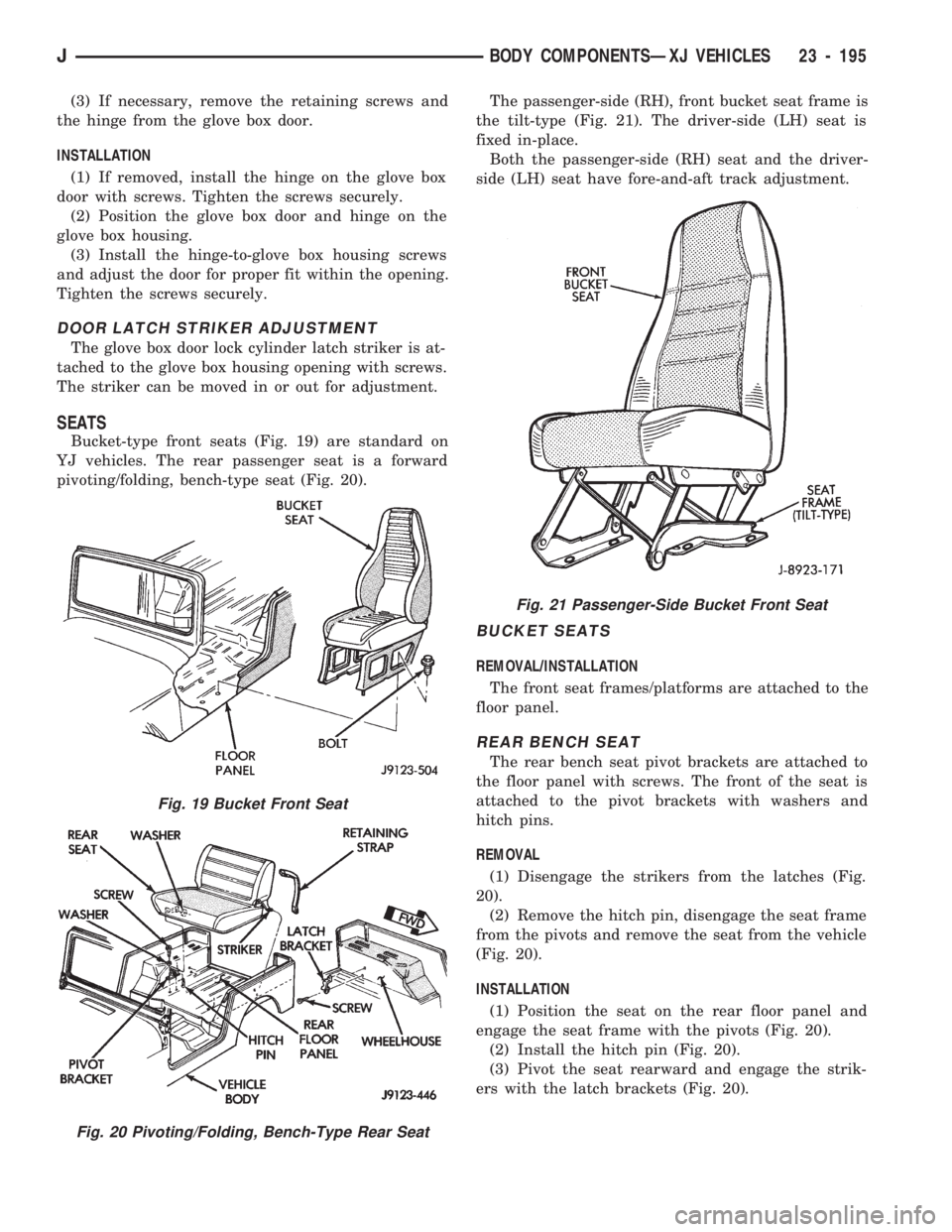
SEATS
Bucket-type front seats (Fig. 19) are standard on
YJ vehicles. The rear passenger seat is a forward
pivoting/folding, bench-type seat (Fig. 20).The passenger-side (RH), front bucket seat frame is
the tilt-type (Fig. 21). The driver-side (LH) seat is
fixed in-place.
Both the passenger-side (RH) seat and the driver-
side (LH) seat have fore-and-aft track adjustment.
BUCKET SEATS
REMOVAL/INSTALLATION
The front seat frames/platforms are attached to the
floor panel.
REAR BENCH SEAT
The rear bench seat pivot brackets are attached to
the floor panel with screws. The front of the seat is
attached to the pivot brackets with washers and
hitch pins.
REMOVAL
(1) Disengage the strikers from the latches (Fig.
20).
(2) Remove the hitch pin, disengage the seat frame
from the pivots and remove the seat from the vehicle
(Fig. 20).
INSTALLATION
(1) Position the seat on the rear floor panel and
engage the seat frame with the pivots (Fig. 20).
(2) Install the hitch pin (Fig. 20).
(3) Pivot the seat rearward and engage the strik-
ers with the latch brackets (Fig. 20).
Fig. 19 Bucket Front Seat
Fig. 20 Pivoting/Folding, Bench-Type Rear Seat
Fig. 21 Passenger-Side Bucket Front Seat
JBODY COMPONENTSÐXJ VEHICLES 23 - 195
Page 1653 of 1784
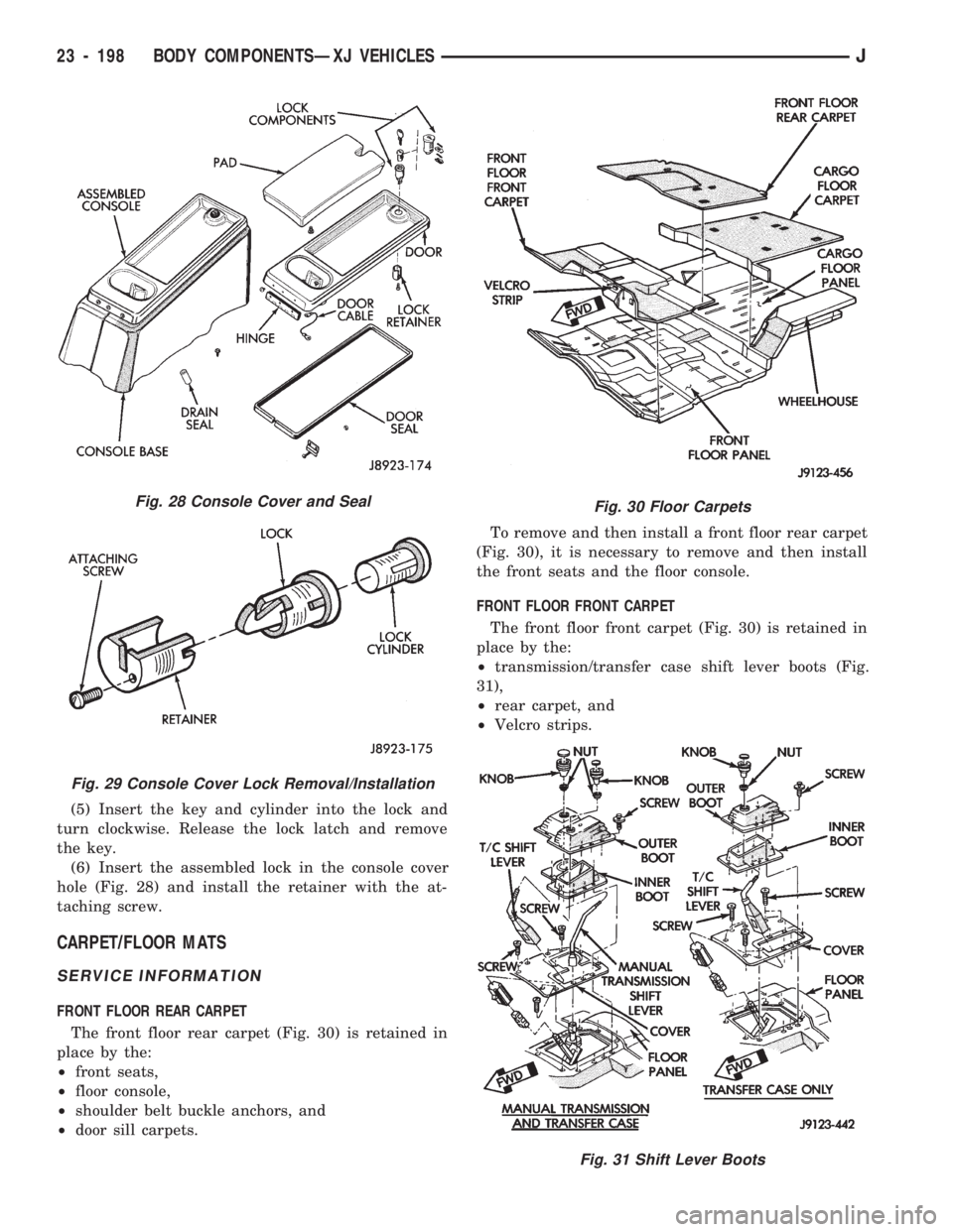
(5) Insert the key and cylinder into the lock and
turn clockwise. Release the lock latch and remove
the key.
(6) Insert the assembled lock in the console cover
hole (Fig. 28) and install the retainer with the at-
taching screw.
CARPET/FLOOR MATS
SERVICE INFORMATION
FRONT FLOOR REAR CARPET
The front floor rear carpet (Fig. 30) is retained in
place by the:
²front seats,
²floor console,
²shoulder belt buckle anchors, and
²door sill carpets.To remove and then install a front floor rear carpet
(Fig. 30), it is necessary to remove and then install
the front seats and the floor console.
FRONT FLOOR FRONT CARPET
The front floor front carpet (Fig. 30) is retained in
place by the:
²transmission/transfer case shift lever boots (Fig.
31),
²rear carpet, and
²Velcro strips.
Fig. 28 Console Cover and Seal
Fig. 29 Console Cover Lock Removal/Installation
Fig. 30 Floor Carpets
Fig. 31 Shift Lever Boots
23 - 198 BODY COMPONENTSÐXJ VEHICLESJ
Page 1754 of 1784
FUSES AND ABBREVIATIONS, SYMBOLS, . . . 8W-6
FUSIBLE LINK REPLACEMENT............8W-4
FUSIBLE LINKS........................8W-3
GALVANIZED METALS, PAINT REPAIR ON . . 23-202
GAP ADJUSTMENT, WHEEL SENSOR AIR....5-49
GAP, REAR SPEED SENSOR AIR............5-3
GASKET FAILURE DIAGNOSIS, ENGINE
CYLINDER HEAD.......................9-5
GASKETS, FORM-IN-PLACE................9-1
GAUGE AND MANIFOLD ASSEMBLY,
PRESSURE..........................24-2
GAUGE CALIBRATION VALUES............8E-22
GAUGE CLUSTER REPLACEMENT.........8E-24
GAUGE, COOLANT TEMPERATURE..........8E-1
GAUGE, FUEL..........................8E-2
GAUGE HOUSINGS, INSTRUMENT
CLUSTER..........................23-190
GAUGE INOPERATIVE, COOLANT
TEMPERATURE.......................8E-3
GAUGE INOPERATIVE, FUEL...............8E-3
GAUGE INOPERATIVE, OIL PRESSURE......8E-3
GAUGE INOPERATIVE, ONE..............8E-22
GAUGE, OIL PRESSURE..................8E-1
GAUGE PACKAGE DIAGNOSIS............8E-22
GAUGE PACKAGE GAUGE REPLACEMENT . . . 8E-24
GAUGE PACKAGE GENERAL
INFORMATION.......................8E-22
GAUGE PACKAGE SERVICE PROCEDURES . . . 8E-24
GAUGE REPLACEMENT, GAUGE
PACKAGE...........................8E-24
GAUGE REPLACEMENTÐINSTRUMENT
CLUSTER REMOVED...................8E-5
GAUGE SENDING UNIT, FUEL.............14-15
GAUGES AND INDICATORS INOPERATIVE....8E-3
GAUGES INOPERATIVE (FIG. 15), ALL......8E-22
GAUGES, INSTRUMENT CLUSTER;
INSTRUMENT PANEL AND GAUGESÐ
XJ ................................8E-13
GAUGES, INSTRUMENT CLUSTER;
INSTRUMENT PANEL AND GAUGESÐ
YJ ................................8E-27
GAUGES, INSTRUMENT PANEL......8A-1 ,8E-27
GAUGES, PRESSURE....................22-2
GAUGESÐXJ, INSTRUMENT PANEL........8E-1
GAUGESÐYJ, INSTRUMENT PANEL........8E-1
GEAR (1) POSITION, HYDRAULIC FLOW
IN MANUAL FIRST...................21-94
GEAR ADJUSTMENTS IN VEHICLE.........19-37
GEAR ADJUSTMENTS ON BENCH.........19-42
GEAR ADJUSTMENTS, STEERING.........19-22
GEAR AND BEARING NOISE; FRONT
SUSPENSION AND AXLE................2-16
GEAR AND BEARING NOISE; REAR
SUSPENSION AND AXLES................3-7
GEAR AND CLUTCH OVERHAUL,
OVERDRIVE PLANETARY..............21-209
GEAR AND NO. 1 ONE-WAY CLUTCH
OVERHAUL, SUN....................21-229
GEAR ASSEMBLY, STEERING.............19-41
GEAR ASSEMBLY/INSTALLATION,
PINION; FRONT SUSPENSION AND AXLE....2-40
GEAR ASSEMBLY/INSTALLATION,
PINION; REAR SUSPENSION AND AXLES....3-22
GEAR CLEANING AND INSPECTION........19-40
GEAR COMPONENTS, FIRSTÐTHIRDÐ
REVERSE..........................21-159
GEAR (CONVERTER CLUTCH
ENGAGED), HYDRAULIC FLOW IN
THIRD.............................21-90
GEAR DEPTH INFORMATION, PINION;
FRONT SUSPENSION AND AXLE..........2-37
GEAR DEPTH INFORMATION, PINION;
REAR SUSPENSION AND AXLES..........3-19
GEAR DEPTH VARIANCE, PINION; FRONT
SUSPENSION AND AXLE................2-38
GEAR DEPTH VARIANCE, PINION; REAR
SUSPENSION AND AXLES...........3-20,3-38
GEAR DISASSEMBLY INFORMATION.......19-24
GEAR, HYDRAULIC FLOW IN D RANGE
FIRST..............................21-87
GEAR, HYDRAULIC FLOW IN D RANGE
SECOND
............................21-88
GEAR, HYDRAULIC FLOW IN D
RANGE THIRD
.......................21-89
GEAR INSTALLATION, RING
...............3-24
GEAR LEAKAGE DIAGNOSIS
..............19-8GEAR, MANUAL STEERING.........19-35,19-73
GEAR OVERDRIVE COMPONENTS,
FOURTH...........................21-158
GEAR OVERHAUL, FRONT PLANETARY....21-228
GEAR OVERHAUL, GOVERNOR AND
PARK .............................21-121
GEAR, POWER STEERING...............19-73
GEAR RATIOS..........................21-2
GEAR RATIOS, TRANSMISSION...........21-33
GEAR, RECIRCULATING BALL POWER
STEERING..........................19-19
GEAR REPLACEMENT, STEERING....19-21,19-43
GEAR SELECTOR INDICATOR
REPLACEMENTÐINSTRUMENT
CLUSTER REMOVED...................8E-6
GEAR SERVICE, GOVERNOR AND PARK . . . 21-101
GEAR SPECIFICATIONS, MANUAL
STEERING..........................19-44
GEAR SPECIFICATIONS, POWER
STEERING..........................19-34
GEAR, SPEED SENSOR ROTORÐ
SPEEDOMETER DRIVE...............21-183
GEAR TRAIN OVERHAUL, PLANETARY.....21-131
GEARÐYJ VEHICLES, MANUAL
STEERING...........................0-32
GEARS, RECIRCULATING-BALL
POWER STEERING...................19-69
GEARSHIFT LINKAGE...................21-70
GEARSHIFT LINKAGE ADJUSTMENT (YJ) . . . 21-96
GEARTRAIN OPERATION AND
APPLICATION CHARTS...............21-159
GENERAL; BATTERY/STARTER/
GENERATOR SERVICE..................8B-7
GENERAL BODY SERVICE INFORMATION....23-1
GENERAL; CHIME/BUZZER WARNING
SYSTEMS...........................8U-1
GENERAL DIAGNOSIS INFORMATION;
CLUTCH..............................6-3
GENERAL DIAGNOSIS INFORMATION;
TRANSMISSION AND TRANSFER
CASE.............................21-167
GENERAL; HEATING AND AIR
CONDITIONING.......................24-8
GENERAL INFORMATION, 2.5L STARTER....8B-4
GENERAL INFORMATION, 4.0L STARTER....8B-6
GENERAL INFORMATION; AUDIO
SYSTEMS........................8F-1,8F-8
GENERAL INFORMATION, BATTERY
TESTING............................8A-3
GENERAL INFORMATION; BATTERY/
STARTER/GENERATOR SERVICE......8B-1,8B-4
GENERAL INFORMATION; BRAKES . . . 5-1,5-7,5-24,
5-39,5-65
GENERAL INFORMATION; CLUTCH..........6-1
GENERAL INFORMATION; COOLING
SYSTEM.................7-1,7-31,7-37,7-38
GENERAL INFORMATION; ELECTRICAL . 8A-1,8A-2,
8A-8,8A-9,8A-14
GENERAL INFORMATION; EMISSION
CONTROL SYSTEMS...................25-1
GENERAL INFORMATION; ENGINES......9-9,9-50
GENERAL INFORMATION; EXHAUST
SYSTEM AND INTAKE MANIFOLD.........11-1
GENERAL INFORMATION; FRAME AND
BUMPERS.......................13-1,13-8
GENERAL INFORMATION; FRONT
SUSPENSION AND AXLE..........2-1,2-5,2-16
GENERAL INFORMATION, FRONT WIPERS/
WASHERS...........................8K-8
GENERAL INFORMATION; FUEL SYSTEM....14-1,
14-12,14-16,14-17,14-32,14-62
GENERAL INFORMATION, GAUGE
PACKAGE...........................8E-22
GENERAL INFORMATION; HEATING
AND AIR CONDITIONING................24-1
GENERAL INFORMATION; HORNS..........8G-1
GENERAL INFORMATION; IGNITION
SYSTEMS
.......8D-1,8D-8,8D-20,8D-30,8D-33
GENERAL INFORMATION, INSTRUMENT
CLUSTER; INSTRUMENT PANEL
AND GAUGESÐXJ
....................8E-1
GENERAL INFORMATION, INSTRUMENT
CLUSTER; INSTRUMENT PANEL AND
GAUGESÐYJ
........................8E-14
GENERAL INFORMATION; LUBRICATION
AND MAINTENANCE
....................0-1GENERAL INFORMATION; PROPELLER
SHAFTS.............................16-1
GENERAL INFORMATION; REAR
SUSPENSION AND AXLES........3-1,3-7,3-11
GENERAL INFORMATION; STEERING........19-1
GENERAL INFORMATION; TRANSMISSION
AND TRANSFER CASE.......21-1,21-32,21-66,
21-69,21-156,21-272,21-293
GENERAL INFORMATION; VEHICLE
SPEED CONTROL SYSTEM..............8H-1
GENERAL INFORMATION; WHEELS AND
TIRES..........................22-1,22-6
GENERAL INFORMATION; WIRING
DIAGRAMS..........................8W-1
GENERAL; POWER DOOR LOCKS..........8P-1
GENERAL; POWER MIRRORS.............8T-1
GENERAL; POWER SEATS................8R-1
GENERAL; REAR WINDOW DEFOGGER......8N-1
GENERAL SERVICE INFORMATION; BODY
COMPONENTSÐXJ VEHICLES.........23-132
GENERAL SERVICE INFORMATION;
BRAKES.........................5-20,5-56
GENERAL SERVICE MAINTENANCE..........0-5
GENERAL SERVICE PROCEDURE
INFORMATION.......................19-69
GENERAL SERVICE, STEERING COLUMN . . . 19-45
GENERAL SPECIFICATIONS, 30RH/32RH . . . 21-322
GENERAL SPECIFICATIONS, AW-4........21-324
GENERATOR DIAGNOSTIC TROUBLE
CODE (DTC)........................8A-19
GENERATOR FIELDÐPCM OUTPUT........14-25
GENERATOR LAMPÐPCM OUTPUT........14-25
GENERATOR REPLACEMENTÐLEFT
HAND DRIVE.........................8B-7
GENERATOR REPLACEMENTÐ
RIGHT HAND DRIVE...................8B-9
GENERATOR SERVICE PROCEDURES.......8B-7
GENERATOR SPECIFICATIONS............8B-12
GENERATOR SPLASH SHIELD............13-14
GENERATOR TEST PROCEDURES ON
VEHICLE...........................8A-14
GLASS AND DOOR OPENING WEATHERSTRIP
SEALS, DOOR WINDOW...............23-62
GLASS, FIXEDÐWATER LEAK
DETECTION AND REPAIR........23-83,23-189
GLASS, FIXED WINDOW..........23-73,23-183
GLASS, FRONT DOOR WINDOW..........23-49
GLASS, FULL-METAL DOOR VENT
WINDOW..........................23-177
GLASS, FULL-METAL DOOR WINDOW.....23-178
GLASS, HARD TOP LIFTGATE............23-162
GLASS, HARD TOP QUARTER WINDOW . . . 23-188
GLASS, REAR DOOR FIXED WINDOW......23-53
GLASS, REAR DOOR WINDOW
...........23-52
GLASS REGULATOR, FRONT DOOR
WINDOW
...........................23-48
GLASS REGULATOR, FULL-METAL
DOOR WINDOW
....................23-177
GLASS REGULATOR HANDLE, FULL-
METAL DOOR WINDOW
..............23-175
GLASS REGULATOR, REAR DOOR
WINDOW
...........................23-51
GLASS REPLACEMENT, WINDSHIELD
......23-75
GLASS, SIGHT
........................24-41
GLASS WEATHERSTRIP SEAL
REPLACEMENT, LIFTGATE
.............23-163
GLASS, WINDSHIELD
..................23-185
GLASSÐXJ VEHICLES, LIFTGATE
WINDOW
...........................23-81
GLASSÐXJ VEHICLES, REAR
QUARTER VENT WINDOW
..............23-80
GLASS/REAR QUARTER PLASTIC INSERT
ÐXJ VEHICLES, QUARTER WINDOW
.....23-80
GLOVE BOX
.........................23-194
GOVERNOR AND PARK GEAR
OVERHAUL
........................21-121
GOVERNOR AND PARK GEAR SERVICE
....21-101
GRID REPAIR, REAR WINDOW
DEFOGGER
..........................8N-2
GRID TEST, REAR WINDOW DEFOGGER
.....8N-1
GRILLE AND GRILLE OPENING PANEL
(GOP)
..............................23-3
GRILLE AND SCREEN, COWL
.......23-11,23-139
GRILLE APPLIQUE, RADIATOR
...........23-134
10 INDEXJ
Description Group-Page Description Group-Page Description Group-Page