1994 JEEP CHEROKEE remove seats
[x] Cancel search: remove seatsPage 50 of 1784
COIL SPRING
REMOVAL
(1) Raise and support the vehicle. Position a hy-
draulic jack under the axle to support it.
(2) Remove the wheel if necessary.
(3) Mark and disconnect the front propeller shaft
from the axle.
(4) Disconnect the lower suspension arms from the
axle (Fig. 6).
(5) Disconnect the stabilizer bar link and shock ab-
sorber from the axle.
(6) Disconnect the track bar from the frame rail
bracket.
(7) Disconnect the drag link from the pitman arm.
(8) Lower the axle until the spring is free from the
upper mount. Remove the coil spring clip (Fig. 6) and
remove the spring.
(9) Remove the jounce bumper if necessary from
the upper spring mount (Fig. 6).
INSTALLATION
(1) Install the jounce bumper on the upper spring
mount. Tighten the bolt to 42 Nzm (31 ft. lbs.) torque
(Fig. 6).
(2) Position the coil spring on the axle pad. Install
the spring clip and bolt (Fig. 6). Tighten bolt to 21
Nzm (16 ft. lbs.) torque.
(3) Raise the axle into position until the spring
seats in the upper mount.
(4) Connect the stabilizer bar links and shock ab-
sorbers to the axle bracket. Connect the track bar to
the frame rail bracket.
(5) Install the lower suspension arms to the axle.
DO NOT TIGHTEN AT THIS TIME.
(6) Install the front propeller shaft to the axle.
(7) Remove the supports and lower the vehicle.
(8) Tighten lower suspension arms nuts to 115
Nzm (85 ft. lbs.) torque.
YJ FRONT SUSPENSION
INDEX
page page
Leaf Spring............................. 14
Leaf Spring Eye Bushing Replacement........ 15
Service Information....................... 13
Shock Absorber.......................... 14Spring and Shock Diagnosis................ 14
Stabilizer Bar............................ 14
Track Bar.............................. 13
SERVICE INFORMATION
It is important to have the springs supporting
the weight of the vehicle when the track bar fas-
teners are being torqued. If the springs are not
at their normal ride position, vehicle ride com-
fort could be affected along with premature rub-
ber bushing wear.
TRACK BAR
REMOVAL
(1) Raise and support the vehicle.
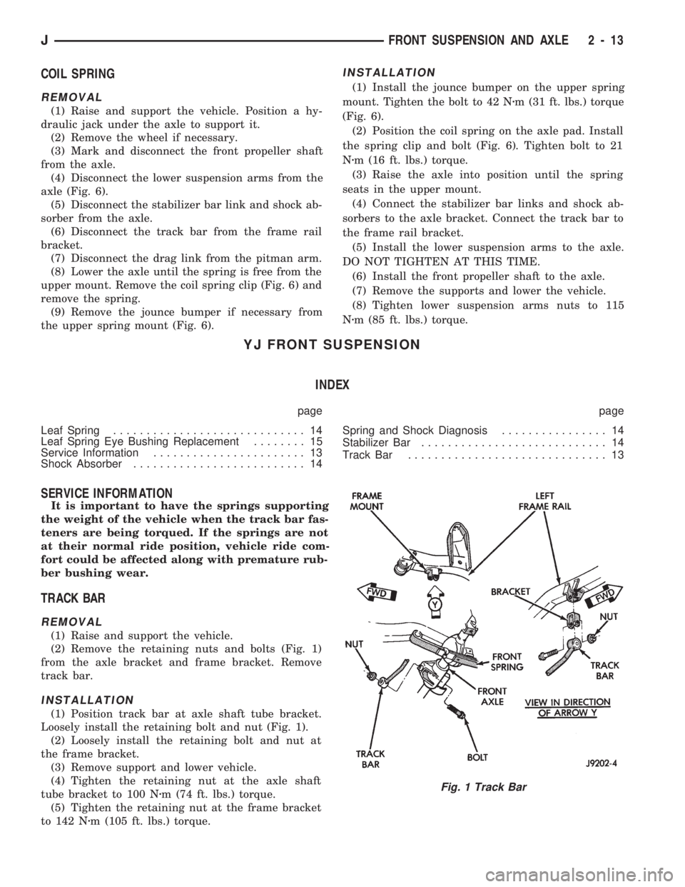
(2) Remove the retaining nuts and bolts (Fig. 1)
from the axle bracket and frame bracket. Remove
track bar.
INSTALLATION
(1) Position track bar at axle shaft tube bracket.
Loosely install the retaining bolt and nut (Fig. 1).
(2) Loosely install the retaining bolt and nut at
the frame bracket.
(3) Remove support and lower vehicle.
(4) Tighten the retaining nut at the axle shaft
tube bracket to 100 Nzm (74 ft. lbs.) torque.
(5) Tighten the retaining nut at the frame bracket
to 142 Nzm (105 ft. lbs.) torque.
Fig. 1 Track Bar
JFRONT SUSPENSION AND AXLE 2 - 13
Page 89 of 1784
(3) Using a brass punch and a hammer, install
lock ring. Carefully tap lock ring clockwise until it
seats against stop on fuel tank.
(4) Connect fuel supply and return hoses to fittings
on fuel pump module. Tighten hose clamps.
(5) Connect fuel pump module electrical harness
connector to main harness connector.
(6) Lower vehicle.
(7) Fill fuel tank. Install fuel tank cap.
(8) Connect negative battery cable.
(9) Start vehicle and inspect for leaks.
REMOVALÐYJ MODELS
The fuel tank must be removed to remove the fuel
pump module.
WARNING: THE FUEL SYSTEM IS UNDER A CON-
STANT PRESSURE (EVEN WITH THE ENGINE OFF).
BEFORE SERVICING THE FUEL PUMP MODULE,
THE FUEL SYSTEM PRESSURE MUST BE RE-
LEASED. REFER TO THE FUEL PRESSURE RE-
LEASE PROCEDURE IN THIS GROUP.
WARNING: EXTINGUISH ALL TOBACCO SMOKING
PRODUCTS BEFORE SERVICING THE FUEL SYS-
TEM. KEEP OPEN FLAME AWAY FROM FUEL SYS-
TEM COMPONENTS.
(1) Remove negative battery cable.
(2) Remove fuel filler cap. Perform the Fuel Pres-
sure Release Procedure as outlined in this group.
(3) Remove fuel tank. Refer to Fuel Tank Remov-
alÐYJ Models.
(4) Remove fuel pump module assembly.
(5) Remove mounting screws. Lift assembly and
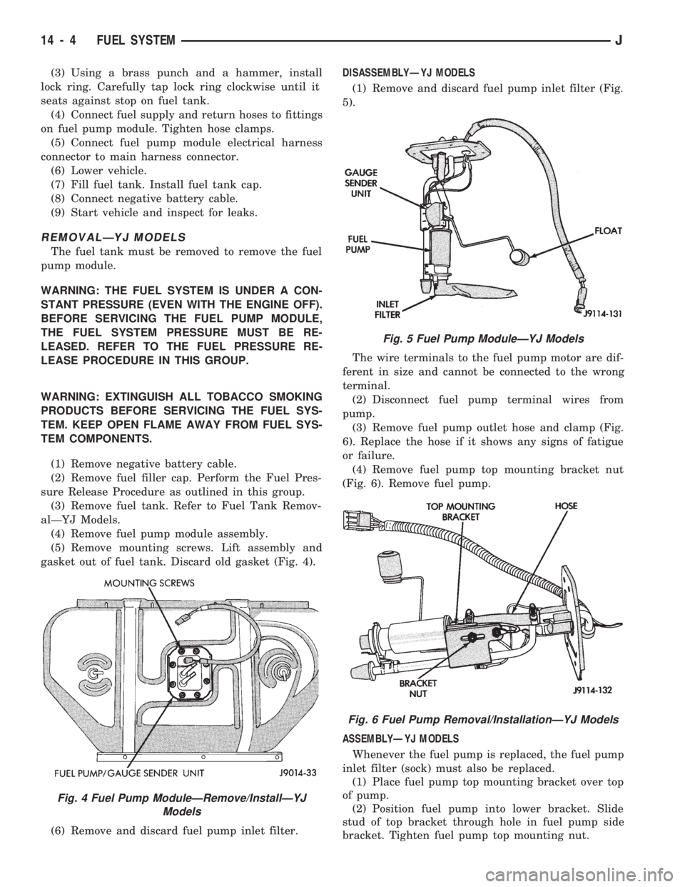
gasket out of fuel tank. Discard old gasket (Fig. 4).
(6) Remove and discard fuel pump inlet filter.DISASSEMBLYÐYJ MODELS
(1) Remove and discard fuel pump inlet filter (Fig.
5).
The wire terminals to the fuel pump motor are dif-
ferent in size and cannot be connected to the wrong
terminal.
(2) Disconnect fuel pump terminal wires from
pump.
(3) Remove fuel pump outlet hose and clamp (Fig.
6). Replace the hose if it shows any signs of fatigue
or failure.
(4) Remove fuel pump top mounting bracket nut
(Fig. 6). Remove fuel pump.
ASSEMBLYÐYJ MODELS
Whenever the fuel pump is replaced, the fuel pump
inlet filter (sock) must also be replaced.
(1) Place fuel pump top mounting bracket over top
of pump.
(2) Position fuel pump into lower bracket. Slide
stud of top bracket through hole in fuel pump side
bracket. Tighten fuel pump top mounting nut.
Fig. 4 Fuel Pump ModuleÐRemove/InstallÐYJ
Models
Fig. 5 Fuel Pump ModuleÐYJ Models
Fig. 6 Fuel Pump Removal/InstallationÐYJ Models
14 - 4 FUEL SYSTEMJ
Page 100 of 1784
INSTALLATIONÐYJ MODELS
(1) Place tank into skid plate. Wrap straps around
tank with strap bolts inserted through holes in skid
plate. Tighten strap nuts to 7.3 Nzm (65 in. lbs.) torque.
(2) Raise skid plate/fuel tank until gauge sender wire
connector can be connected to harness connector.
(3) Finish raising skid plate/fuel tank assembly
into position. Tighten mounting nuts to 16 Nzm (12
ft. lbs.) torque. Remove transmission jack.
(4) Connect fuel fill hose and fill vent hose to filler
neck. Tighten hose clamps.
(5) Connect vent hose to vent tube.
(6) Connect fuel supply hose to the supply tube and
fuel return hose to return tube. Tighten hose clamps.
(7) Install fuel filler neck shroud with push clips.
(8) Lower vehicle.
(9) Fill fuel tank. Install filler cap.
(10) Connect negative battery cable to battery.
(11) Start vehicle and inspect for leaks.
FUEL GAUGE SENDING UNIT
The fuel gauge sending unit is attached to the fuel
pump module. Refer to Fuel Pump Module in the
Fuel Delivery System section of this group.
FUEL TANK PRESSURE RELIEF/ROLLOVER VALVE
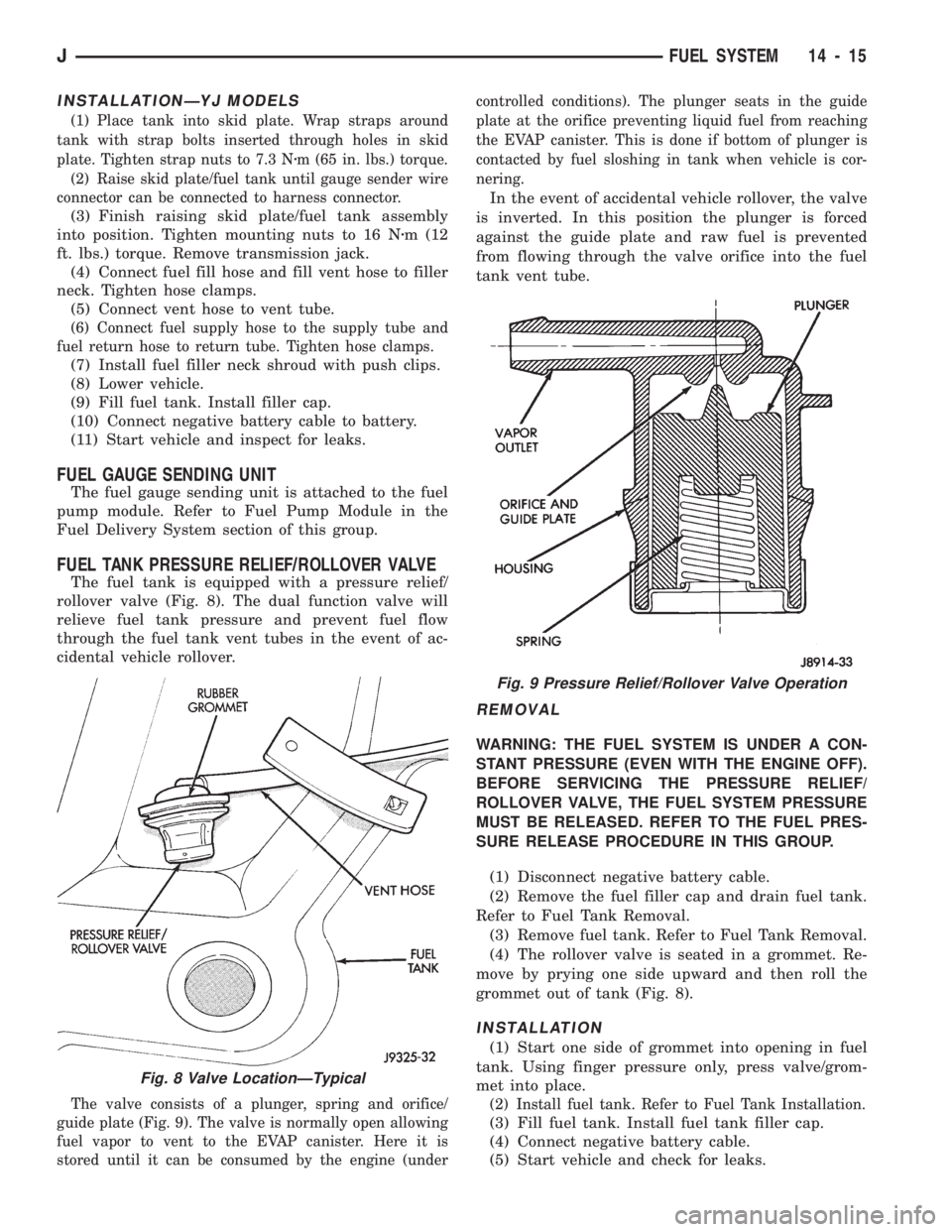
The fuel tank is equipped with a pressure relief/
rollover valve (Fig. 8). The dual function valve will
relieve fuel tank pressure and prevent fuel flow
through the fuel tank vent tubes in the event of ac-
cidental vehicle rollover.
The valve consists of a plunger, spring and orifice/
guide plate (Fig. 9). The valve is normally open allowing
fuel vapor to vent to the EVAP canister. Here it is
stored until it can be consumed by the engine (undercontrolled conditions). The plunger seats in the guide
plate at the orifice preventing liquid fuel from reaching
the EVAP canister. This is done if bottom of plunger is
contacted by fuel sloshing in tank when vehicle is cor-
nering.
In the event of accidental vehicle rollover, the valve
is inverted. In this position the plunger is forced
against the guide plate and raw fuel is prevented
from flowing through the valve orifice into the fuel
tank vent tube.
REMOVAL
WARNING: THE FUEL SYSTEM IS UNDER A CON-
STANT PRESSURE (EVEN WITH THE ENGINE OFF).
BEFORE SERVICING THE PRESSURE RELIEF/
ROLLOVER VALVE, THE FUEL SYSTEM PRESSURE
MUST BE RELEASED. REFER TO THE FUEL PRES-
SURE RELEASE PROCEDURE IN THIS GROUP.
(1) Disconnect negative battery cable.
(2) Remove the fuel filler cap and drain fuel tank.
Refer to Fuel Tank Removal.
(3) Remove fuel tank. Refer to Fuel Tank Removal.
(4) The rollover valve is seated in a grommet. Re-
move by prying one side upward and then roll the
grommet out of tank (Fig. 8).
INSTALLATION
(1) Start one side of grommet into opening in fuel
tank. Using finger pressure only, press valve/grom-
met into place.
(2) Install fuel tank. Refer to Fuel Tank Installation.
(3) Fill fuel tank. Install fuel tank filler cap.
(4) Connect negative battery cable.
(5) Start vehicle and check for leaks.
Fig. 8 Valve LocationÐTypical
Fig. 9 Pressure Relief/Rollover Valve Operation
JFUEL SYSTEM 14 - 15
Page 336 of 1784
INSTALLATION
(1) Install coolant temperature sensor into the
thermostat housing. Tighten to 28 Nzm (21 ft. lbs.)
torque.
(2) Connect the wire connector.
(3) Fill the cooling system. Refer to group 7, Cool-
ing System.
DISTRIBUTOR
All distributors contain an internal oil seal that
prevents oil from entering the distributor housing.
The seal is not serviceable.
The camshaft position sensor is located in the dis-
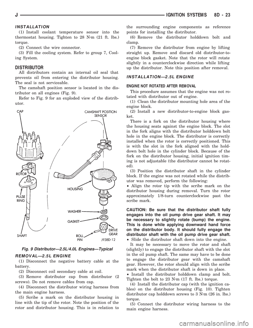
tributor on all engines (Fig. 9).
Refer to Fig. 9 for an exploded view of the distrib-
utor.
REMOVALÐ2.5L ENGINE
(1) Disconnect the negative battery cable at the
battery.
(2) Disconnect coil secondary cable at coil.
(3) Remove distributor cap from distributor (2
screws). Do not remove cables from cap.
(4) Disconnect the distributor wiring harness from
the main engine harness.
(5) Scribe a mark on the distributor housing in
line with the tip of the rotor. Note the position of the
rotor and distributor housing. This is in relation tothe surrounding engine components as reference
points for installing the distributor.
(6) Remove the distributor holddown bolt and
clamp.
(7) Remove the distributor from engine by lifting
straight up. Remove and discard old distributor-to-
engine block gasket. Note that the rotor will rotate
slightly in a counterclockwise direction while lifting
up the distributor. Note this position after removal.
INSTALLATIONÐ2.5L ENGINE
ENGINE NOT ROTATED AFTER REMOVAL
This procedure assumes that the engine was not ro-
tated with distributor out of engine.
(1) Clean the distributor mounting hole area of the
engine block.
(2) Install a new distributor-to-engine block gas-
ket.
There is a fork on the distributor housing where
the housing seats against the engine block. The slot
in the fork aligns with the distributor holddown bolt
hole in the engine block. The distributor is correctly
installed when the rotor is correctly positioned. This
is with the slot in the fork aligned with the hold-
down bolt hole in the cylinder block. Because of the
fork on the distributor housing, initial ignition tim-
ing is not adjustable (the distributor cannot be rotat-
ed).
(3) Position the distributor shaft in the cylinder
block. If the engine was not rotated while the distrib-
utor was removed, perform the following:
²Align the rotor tip with the scribe mark on the
distributor housing during removal. Turn the rotor
approximately 1/8-turn counterclockwise past the
scribe mark.
CAUTION: Be sure that the distributor shaft fully
engages into the oil pump drive gear shaft. It may
be necessary to slightly rotate (bump) the engine.
This is done while applying downward hand force
on the distributor body. It should fully engage the
distributor shaft with the oil pump drive gear shaft.
²Slide the distributor shaft down into the engine.
It may be necessary to move the rotor and shaft
(slightly) to engage the distributor shaft with the slot
in the oil pump shaft. The same may have to be done
to engage the distributor gear with the camshaft
gear. However, the rotor should align with the scribe
mark when the distributor shaft is down in place.
²Install the distributor holddown clamp and bolt.
Tighten the bolt to 23 Nzm (17 ft. lbs.) torque.
(4) Install the distributor cap (with the ignition ca-
bles) on the distributor housing (Fig. 10). Tighten
distributor cap holddown screws to 3 Nzm (26 in. lbs.)
torque.
(5) Connect the distributor wiring harness to the
main engine harness.
Fig. 9 DistributorÐ2.5L/4.0L EnginesÐTypical
JIGNITION SYSTEMS 8D - 23
Page 337 of 1784
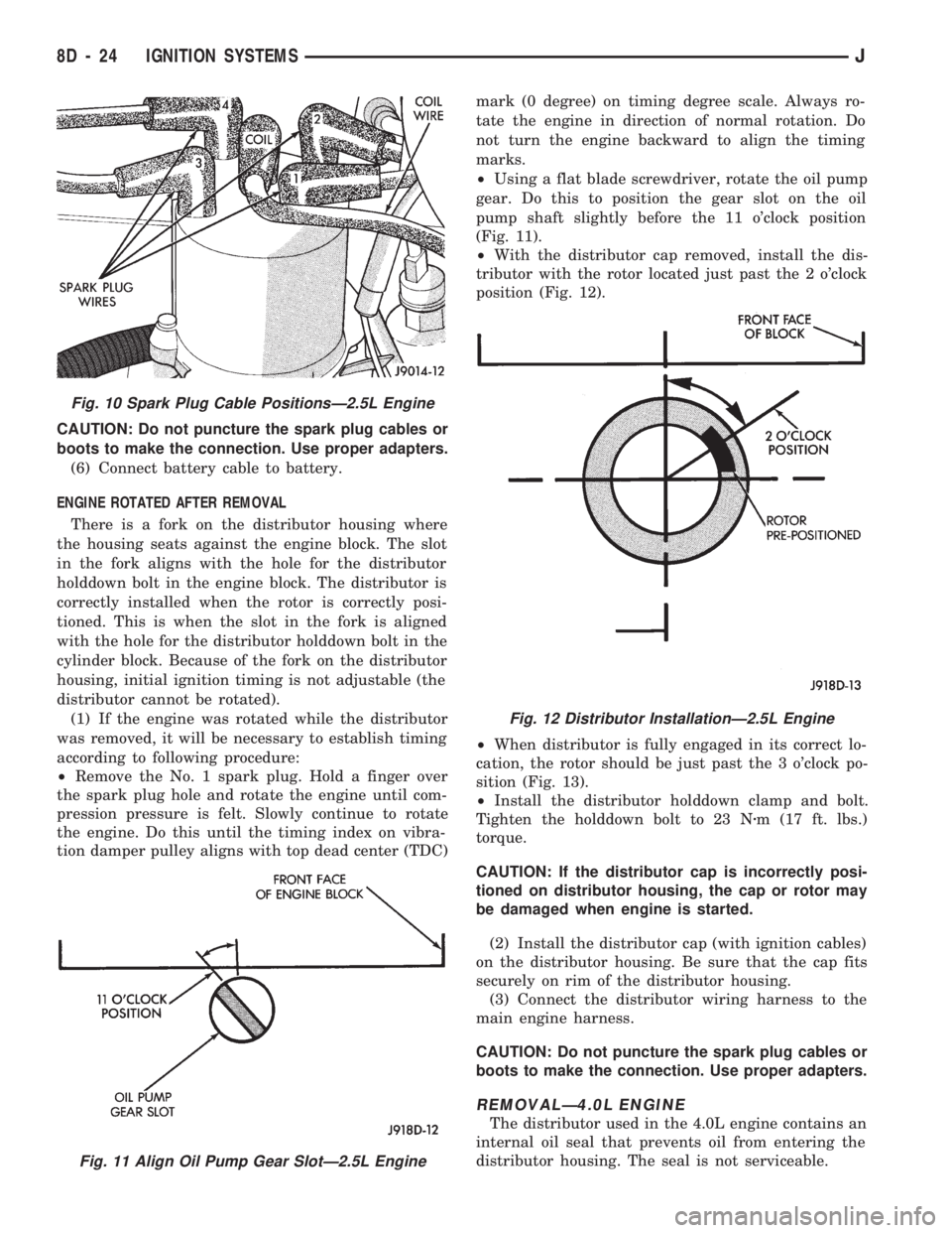
CAUTION: Do not puncture the spark plug cables or
boots to make the connection. Use proper adapters.
(6) Connect battery cable to battery.
ENGINE ROTATED AFTER REMOVAL
There is a fork on the distributor housing where
the housing seats against the engine block. The slot
in the fork aligns with the hole for the distributor
holddown bolt in the engine block. The distributor is
correctly installed when the rotor is correctly posi-
tioned. This is when the slot in the fork is aligned
with the hole for the distributor holddown bolt in the
cylinder block. Because of the fork on the distributor
housing, initial ignition timing is not adjustable (the
distributor cannot be rotated).
(1) If the engine was rotated while the distributor
was removed, it will be necessary to establish timing
according to following procedure:
²Remove the No. 1 spark plug. Hold a finger over
the spark plug hole and rotate the engine until com-
pression pressure is felt. Slowly continue to rotate
the engine. Do this until the timing index on vibra-
tion damper pulley aligns with top dead center (TDC)mark (0 degree) on timing degree scale. Always ro-
tate the engine in direction of normal rotation. Do
not turn the engine backward to align the timing
marks.
²Using a flat blade screwdriver, rotate the oil pump
gear. Do this to position the gear slot on the oil
pump shaft slightly before the 11 o'clock position
(Fig. 11).
²With the distributor cap removed, install the dis-
tributor with the rotor located just past the 2 o'clock
position (Fig. 12).
²When distributor is fully engaged in its correct lo-
cation, the rotor should be just past the 3 o'clock po-
sition (Fig. 13).
²Install the distributor holddown clamp and bolt.
Tighten the holddown bolt to 23 Nzm (17 ft. lbs.)
torque.
CAUTION: If the distributor cap is incorrectly posi-
tioned on distributor housing, the cap or rotor may
be damaged when engine is started.
(2) Install the distributor cap (with ignition cables)
on the distributor housing. Be sure that the cap fits
securely on rim of the distributor housing.
(3) Connect the distributor wiring harness to the
main engine harness.
CAUTION: Do not puncture the spark plug cables or
boots to make the connection. Use proper adapters.
REMOVALÐ4.0L ENGINE
The distributor used in the 4.0L engine contains an
internal oil seal that prevents oil from entering the
distributor housing. The seal is not serviceable.
Fig. 11 Align Oil Pump Gear SlotÐ2.5L Engine
Fig. 10 Spark Plug Cable PositionsÐ2.5L Engine
Fig. 12 Distributor InstallationÐ2.5L Engine
8D - 24 IGNITION SYSTEMSJ
Page 469 of 1784
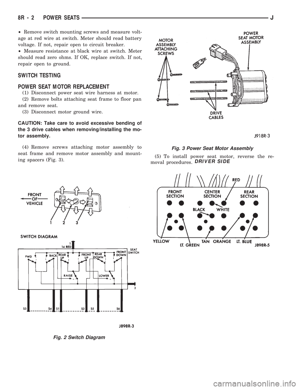
²Remove switch mounting screws and measure volt-
age at red wire at switch. Meter should read battery
voltage. If not, repair open to circuit breaker.
²Measure resistance at black wire at switch. Meter
should read zero ohms. If OK, replace switch. If not,
repair open to ground.
SWITCH TESTING
POWER SEAT MOTOR REPLACEMENT
(1) Disconnect power seat wire harness at motor.
(2) Remove bolts attaching seat frame to floor pan
and remove seat.
(3) Disconnect motor ground wire.
CAUTION: Take care to avoid excessive bending of
the 3 drive cables when removing/installing the mo-
tor assembly.
(4) Remove screws attaching motor assembly to
seat frame and remove motor assembly and mount-
ing spacers (Fig. 3).(5) To install power seat motor, reverse the re-
moval procedures.
Fig. 2 Switch Diagram
DRIVER SIDE
Fig. 3 Power Seat Motor Assembly
8R - 2 POWER SEATSJ
Page 863 of 1784
REMOVAL
Each valve spring is held in place by a retainer
and a set of conical valve locks. The locks can be re-
moved only by compressing the valve spring.
(1) Remove the engine cylinder head cover.
(2) Remove capscrews, bridge and pivot assemblies
and rocker arms for access to each valve spring to be
removed.
(3) Remove push rods. Retain the push rods,
bridges, pivots and rocker arms in the same order
and position as removed.
(4) Inspect the springs and retainer for cracks and
possible signs of weakening.
(5) Remove the spark plug(s) adjacent to the cylin-
der(s) below the valve springs to be removed.
(6) Install a 14 mm (1/2 inch) (thread size) air hose
adaptor in the spark plug hole.
(7) Connect an air hose to the adapter and apply
air pressure slowly. Maintain at least 621 kPa (90
psi) of air pressure in the cylinder to hold the valves
against their seats. For vehicles equipped with an air
conditioner, use a flexible air adaptor when servicing
the No.1 cylinder.
(8) Tap the retainer or tip with a rawhide hammer
to loosen the lock from the retainer. Use Valve
Spring Compressor Tool MD-998772A to compress
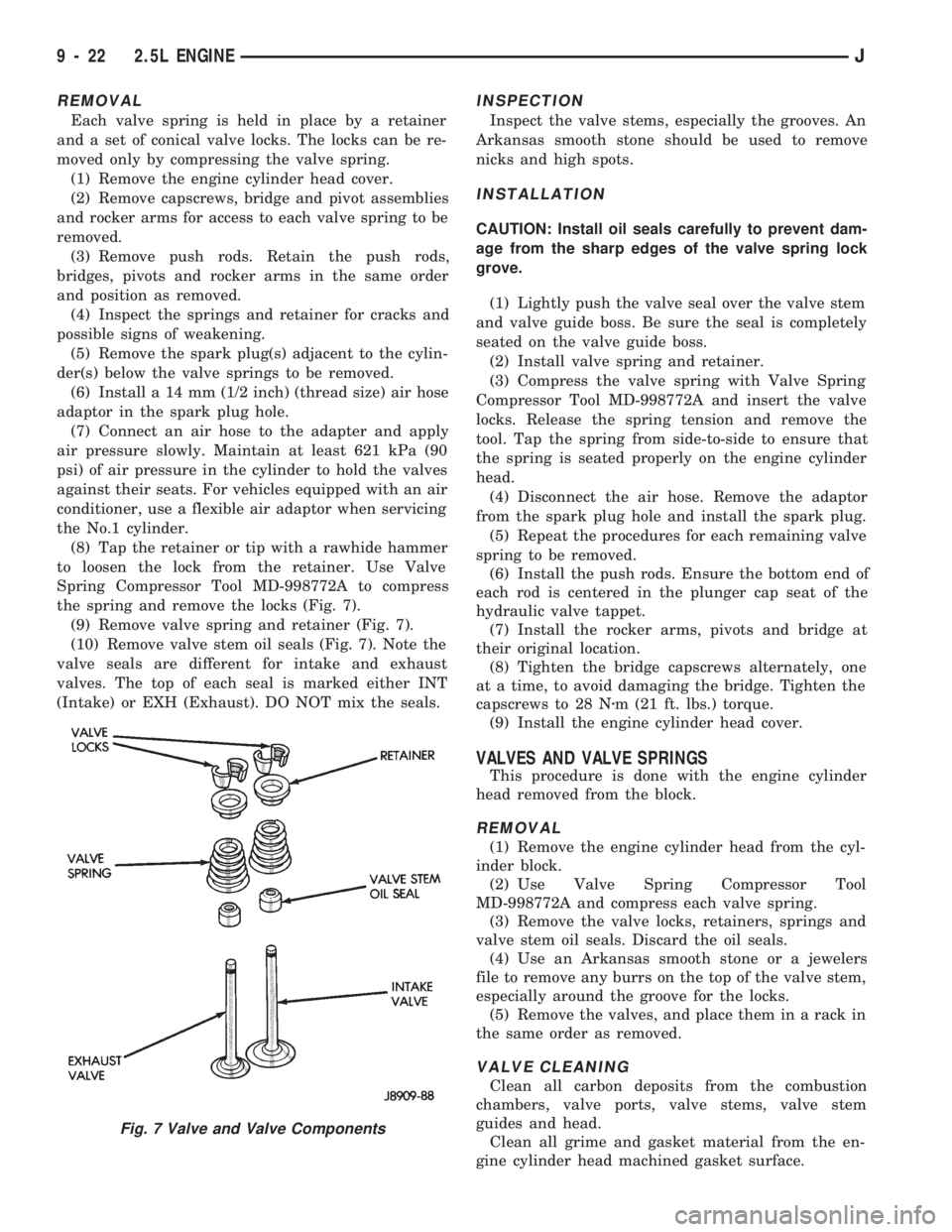
the spring and remove the locks (Fig. 7).
(9) Remove valve spring and retainer (Fig. 7).
(10) Remove valve stem oil seals (Fig. 7). Note the
valve seals are different for intake and exhaust
valves. The top of each seal is marked either INT
(Intake) or EXH (Exhaust). DO NOT mix the seals.
INSPECTION
Inspect the valve stems, especially the grooves. An
Arkansas smooth stone should be used to remove
nicks and high spots.
INSTALLATION
CAUTION: Install oil seals carefully to prevent dam-
age from the sharp edges of the valve spring lock
grove.
(1) Lightly push the valve seal over the valve stem
and valve guide boss. Be sure the seal is completely
seated on the valve guide boss.
(2) Install valve spring and retainer.
(3) Compress the valve spring with Valve Spring
Compressor Tool MD-998772A and insert the valve
locks. Release the spring tension and remove the
tool. Tap the spring from side-to-side to ensure that
the spring is seated properly on the engine cylinder
head.
(4) Disconnect the air hose. Remove the adaptor
from the spark plug hole and install the spark plug.
(5) Repeat the procedures for each remaining valve
spring to be removed.
(6) Install the push rods. Ensure the bottom end of
each rod is centered in the plunger cap seat of the
hydraulic valve tappet.
(7) Install the rocker arms, pivots and bridge at
their original location.
(8) Tighten the bridge capscrews alternately, one
at a time, to avoid damaging the bridge. Tighten the
capscrews to 28 Nzm (21 ft. lbs.) torque.
(9) Install the engine cylinder head cover.
VALVES AND VALVE SPRINGS
This procedure is done with the engine cylinder
head removed from the block.
REMOVAL
(1) Remove the engine cylinder head from the cyl-
inder block.
(2) Use Valve Spring Compressor Tool
MD-998772A and compress each valve spring.
(3) Remove the valve locks, retainers, springs and
valve stem oil seals. Discard the oil seals.
(4) Use an Arkansas smooth stone or a jewelers
file to remove any burrs on the top of the valve stem,
especially around the groove for the locks.
(5) Remove the valves, and place them in a rack in
the same order as removed.
VALVE CLEANING
Clean all carbon deposits from the combustion
chambers, valve ports, valve stems, valve stem
guides and head.
Clean all grime and gasket material from the en-
gine cylinder head machined gasket surface.
Fig. 7 Valve and Valve Components
9 - 22 2.5L ENGINEJ
Page 864 of 1784
INSPECTION
Inspect for cracks in the combustion chambers and
valve ports.
Inspect for cracks on the exhaust seat.
Inspect for cracks in the gasket surface at each
coolant passage.
Inspect valves for burned, cracked or warped heads.
Inspect for scuffed or bent valve stems.
Replace valves displaying any damage.
VALVE REFACING
(1) Use a valve refacing machine to reface the in-
take and exhaust valves to the specified angle.
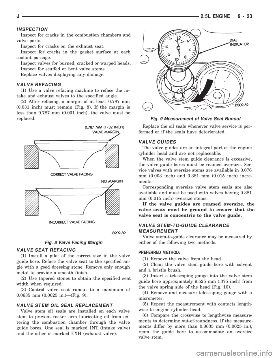
(2) After refacing, a margin of at least 0.787 mm
(0.031 inch) must remain (Fig. 8). If the margin is
less than 0.787 mm (0.031 inch), the valve must be
replaced.
VALVE SEAT REFACING
(1) Install a pilot of the correct size in the valve
guide bore. Reface the valve seat to the specified an-
gle with a good dressing stone. Remove only enough
metal to provide a smooth finish.
(2) Use tapered stones to obtain the specified seat
width when required.
(3) Control valve seat runout to a maximum of
0.0635 mm (0.0025 in.)Ð(Fig. 9).
VALVE STEM OIL SEAL REPLACEMENT
Valve stem oil seals are installed on each valve
stem to prevent rocker arm lubricating oil from en-
tering the combustion chamber through the valve
guide bores. One seal is marked INT (intake valve)
and the other is marked EXH (exhaust valve).Replace the oil seals whenever valve service is per-
formed or if the seals have deteriorated.
VALVE GUIDES
The valve guides are an integral part of the engine
cylinder head and are not replaceable.
When the valve stem guide clearance is excessive,
the valve guide bores must be reamed oversize. Ser-
vice valves with oversize stems are available in 0.076
mm (0.003 inch) and 0.381 mm (0.015 inch) incre-
ments.
Corresponding oversize valve stem seals are also
available and must be used with valves having 0.381
mm (0.015 inch) oversize stems.
If the valve guides are reamed oversize, the
valve seats must be ground to ensure that the
valve seat is concentric to the valve guide.
VALVE STEM-TO-GUIDE CLEARANCE
MEASUREMENT
Valve stem-to-guide clearance may be measured by
either of the following two methods.
PREFERRED METHOD:
(1) Remove the valve from the head.
(2) Clean the valve stem guide bore with solvent
and a bristle brush.
(3) Insert a telescoping gauge into the valve stem
guide bore approximately 9.525 mm (.375 inch) from
the valve spring side of the head (Fig. 10).
(4) Remove and measure telescoping gauge with a
micrometer.
(5) Repeat the measurement with contacts length-
wise to engine cylinder head.
(6) Compare the crosswise to lengthwise measure-
ments to determine out-of-roundness. If the measure-
ments differ by more than 0.0635 mm (0.0025 in.),
ream the guide bore to accommodate an oversize
valve stem.
Fig. 8 Valve Facing Margin
Fig. 9 Measurement of Valve Seat Runout
J2.5L ENGINE 9 - 23